From a discussion on the Makergear 3D printer forums …
A Makergear M2 user encountered a temperature control problem:
Problem: Temperature fluctuation on the hotend +/- 7 degrees C when set in the controls. A little more extreme when printing (~+/- 15).
Slow cycling like that indicates the hot end’s PID loop coefficients don’t match reality.
Preheat the extruder to maybe 200 °C, run a PID calibration (M303), store the results in EEPROM (M500), and that should do the trick.
PID coefficients depend on the hot end’s physical condition, so you should re-do the calibration whenever anything changes on the hot end. Even removing & reinstalling the same hardware will change the contact points between, say, the thermistor and its hole in the hot end.
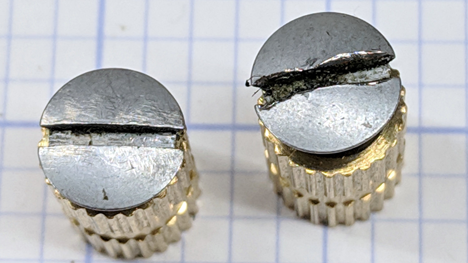
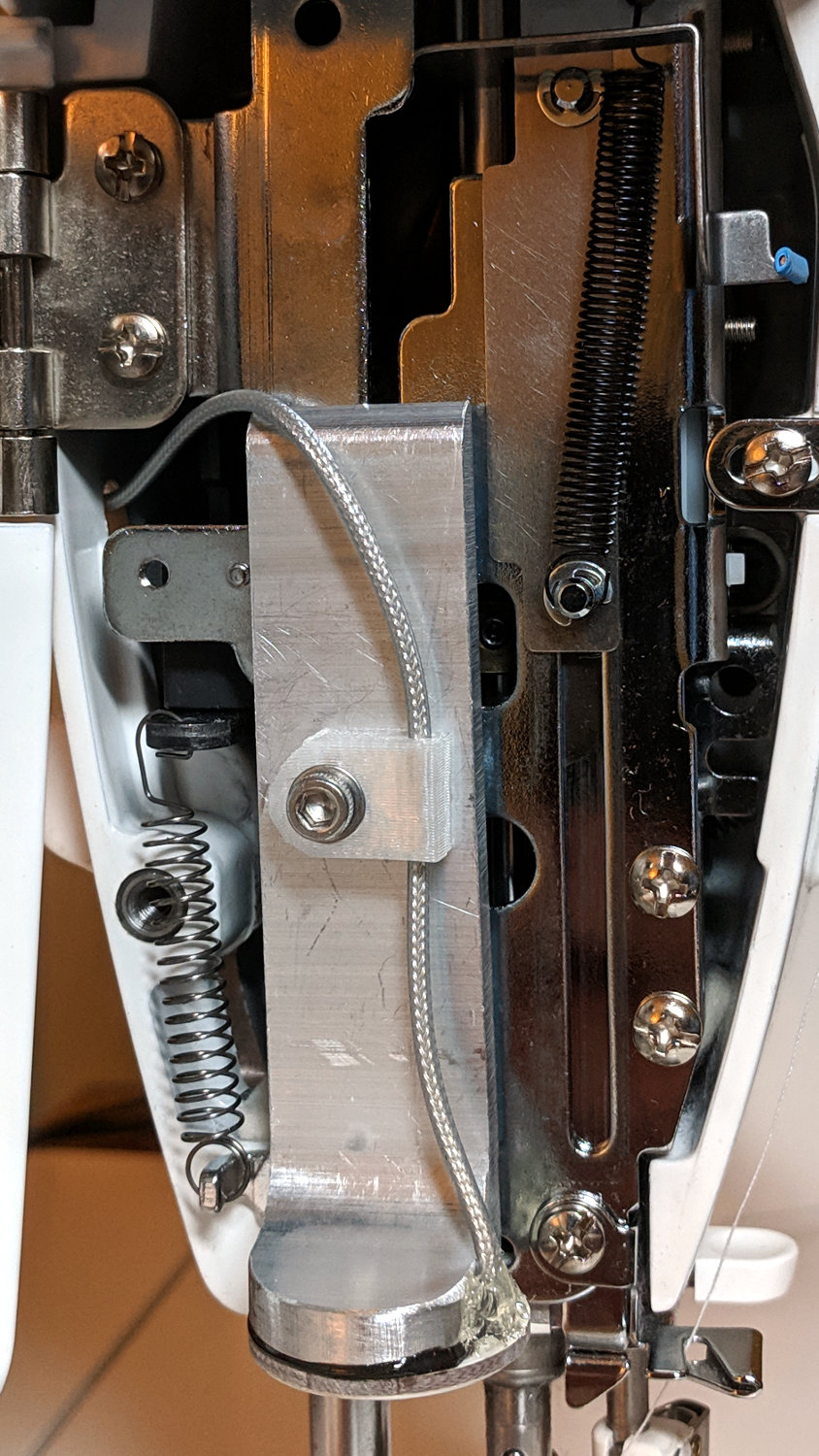
A dab of good heatsink compound on the thermistor should stabilize its contact with the hot end, although that will change the reported temperature and PID coefficients. Probably doesn’t make any real difference, but I felt better:

Which prompted a question from a user who regularly swaps entire hot ends to change nozzle diameters:
run a pid cal when I set my starting height each time I switch?
Assuming you swap entire hot ends, including their thermistor & heater, then you can calibrate each one, write down its PID values, manually set ’em with M301 when you install it, then use M500 to store ’em in EEPROM.
Because you bend those fragile thermistor wires every time you swap hot ends, keep a couple thermistors on hand. You’ll need ’em.