Ed Nisley's Blog: Shop notes, electronics, firmware, machinery, 3D printing, laser cuttery, and curiosities. Contents: 100% human thinking, 0% AI slop.
Ordered 100 stainless steel M3 washers from a “US Seller”, received this:
M3 stainless steel washers – short count
Yeah, it looked a bit short to me, too.
The chopped and bent washers in the upper right corner suggest the seller got floor sweepings from his source, which is about what you’d expect for a bottom-dollar vendor.
The seller refunded half, which wasn’t particularly generous, but I wasn’t ready to go to the mat for two bucks.
Unfortunately, the thermal tape on one of the CPU heatsinks was sufficiently wrinkled to prevent good contact with the CPU:
RPi taped heatsinks – as received
The seller sent a replacement copper slug with tape on one side. Presumably, they glue it to the heatsink with thermal silicone:
Moster RPi Heatsink – silicone adhesive
Of which, I have none on hand.
So I did what I should have done originally, which was to drop a few bucks on a lifetime supply of thermally conductive heatsink tape, apply it to the bare side of the slug and stick the slug to the heatsink with their tape:
Moster RPi Heatsink – replacement adhesive tape
The blue stuff is the separation film, with the tape being white. It doesn’t match the black tape on the other side, but seems gooey enough to work.
Done!
Despite the heatsink hype, ball grid array chips dissipate most of their heat through their pads (and perhaps a central thermal pad) into the PCB, so sticking a heatsink atop the package is largely decorative, along the lines of hotrod ornamentation.
The epoxy packages used in previous Raspberry Pi iterations had better thermal conductivity to their top surface:
RPi 3 B – epoxy CPU
Than the more recent metal-top packages, which surely have inert-gas fill under the lid:
Yes, the heatsink does conduct some heat into the air, even if not nearly as much as you might want.
(*) I’m pretty sure “Moster” was a typo in the original eBay listing which took on a life of its own to become something of an unofficial trademark. All of the search results ship from Duluth, Georgia (USA), regardless of the nominal seller; feel free to draw your own conclusions.
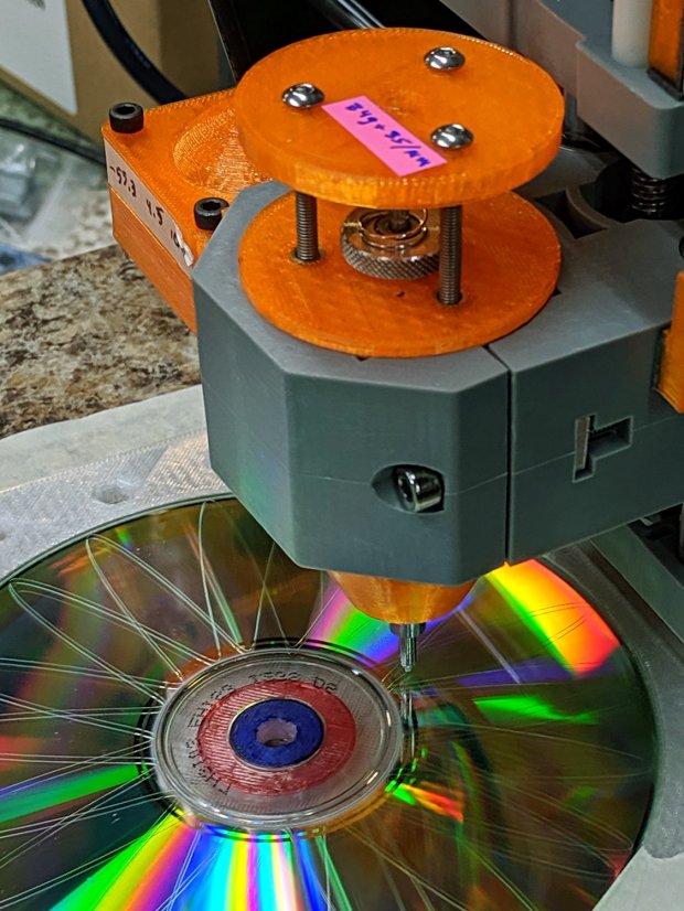
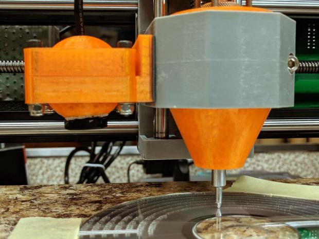
With the 3018-Pro used for drag engraving on CDs and hard drive platters, there’s no need for all the clearance below the Z-axis carriage required for the OEM motor and ER11 collet chuck. A chunk of laminate countertop and a hunk of Celotex foam insulation produce a nicely flat surface 47 mm above the platform:
CNC 3018 Table Riser
It’s surprisingly flat:
Table Flatness Measurement – 2019-08-30
Those are millimeters of clearance between the gray plastic clamp around the diamond drag tool holder (about which, more later) and my trusty bench block, measured at 50 mm intervals across the platform. The lower figures appeared after tightening the upper-left screw by a little over 1/6 turn = 0.2 mm, making the entire platform flat & aligned within ±0.1 mm.
Yeah, not bad for a scrap countertop!
The four M6 socket head cap screws pass through the stack into T-nuts in the platform:
CNC 3018 Table Riser – screw clearance
The countertop was thick enough to allow countersinking the screws slightly below the surface:
CNC 3018 Table Riser – screw countersink
I transfer-punched the screw clearance hole locations into the Celotex and drilled it with an ordinary twist drill. It wasn’t pretty, but nobody will ever notice.
Two sheets, maybe 1 mm thick, of closed-cell foam below the Celotext provide enough squish to align the top surface without straining anything. The screws are firmly tight, so they shouldn’t work their way loose under minimal engraving loads.
Taping the CDs to the surface works well for now, although a simpler version of the fixture may be in order.
Which suggested putting it in a ball mount for E-Z aiming:
CNC 3018-Pro – Probe Camera – ball mount
Black filament snippets serve as alignment pins to hold the ball halves together while they’re getting clamped. They’re epoxied into the upper half of the ball, because who knows when I’ll need to harvest the camera.
USB Camera – Round PCB Mount – solid model – build
The clamp pieces fit around the ball with four M3 screws providing the clamping force:
USB Camera – Round PCB Mount – solid model sectioned
The whole affair sticks onto the Z axis carrier with double-sided foam tape:
CNC 3018-Pro – Probe Camera – alignment
It barely clears the strut on the -X side of the carriage, although it does stick out over the edge of the chassis.
After the fact, I tucked a closed-cell foam ring between the lens threads and the ball housing to stabilize the lens; the original camera glued the thing in place, but some fiddly alignment & focusing lies ahead:
Alignment mirror – collimation
It’s worth noting that the optical axis of these cheap cameras rarely coincides with the physical central axis of the lens. This one requires a jaunty tilt, although it’s not noticeable in any of the pictures I tried to take.
This file contains hidden or bidirectional Unicode text that may be interpreted or compiled differently than what appears below. To review, open the file in an editor that reveals hidden Unicode characters.
Learn more about bidirectional Unicode characters
The ball-shaped Logitch QuickCam Pro 5000 has a rectangular PCB, so conjuring a case wasn’t too challenging:
Probe Camera Case – Logitech QuickCam Pro 5000 – bottom
That’s more-or-less matte black duct tape to cut down reflections.
The top side has a cover made from scuffed acrylic scrap:
Probe Camera Case – Logitech QuickCam Pro 5000 – top
The corners are slightly rounded to fit under the screw heads holding it in place.
The solid model shows off the internal ledge positioning the PCB so the camera lens housing rests on the floor:
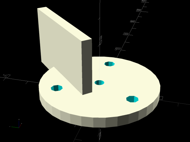
3018 Probe Camera Mount – solid model
The notch lets the cable out, while keeping it in one place and providing some strain relief.
I though if a camera was recognized by V4L2 and worked with VLC, it was good to go:
Logitech QuickCam Pro 5000 – short focus
Regrettably, it turns out the camera has a pixel format incompatible with the Python opencv interface used by bCNC. This may have something to do with running the code on a Raspberry Pi, rather than an x86 box.
The camera will surely come in handy for something else, especially with such a cute case.
This file contains hidden or bidirectional Unicode text that may be interpreted or compiled differently than what appears below. To review, open the file in an editor that reveals hidden Unicode characters.
Learn more about bidirectional Unicode characters
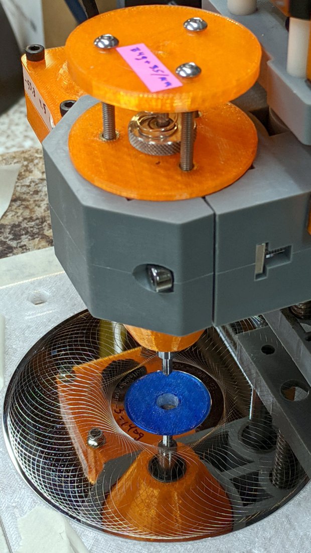
Up to this point, the Sherline has been drilling 3.5 inch hard drive platters to serve as as reflecting bases for the vacuum tubes:
LinuxCNC – Sherline Mill – Logitech Gamepad
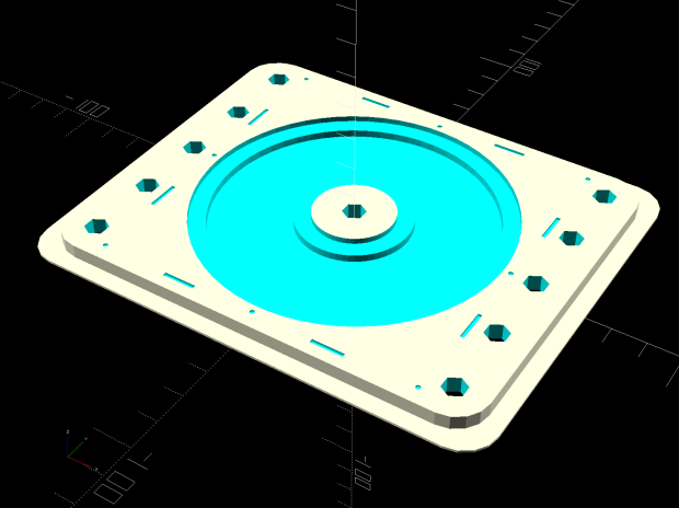
The CNC 3018-Pro has a work envelope large enough for CD / DVD platters, so I mashed the Sherline fixture with dimensions from the vacuum tube code, added the 3018’s T-slot spacing, and conjured a pair of fixtures for a pair of machines.
Because I expect to practice on scrap CDs and DVDs for a while:
Platter Fixtures – CD on 3018
And a 3.5 inch hard drive platter version:
Platter Fixtures – hard drive platter on 3018
The holes sit at half the 3018’s T-slot spacing (45 mm / 2), so you can nudge the fixtures to the front or rear, as you prefer.
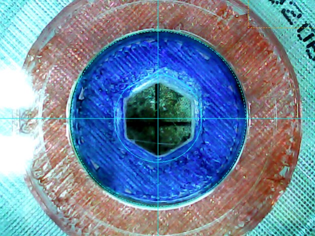
The alignment dots & slots should help touch off the XY coordinate system on the Sherline, although it can’t reach all of a CD. Using bCNC’s video alignment on the hub hole will be much easier on the 3018.
After fiddling around with the 3018 for a while, however, the CD fixture doesn’t have many advantages over simply taping the disc to a flat platen. Obviously, you’d want a sacrificial layer for drilling, but it’s not clear the OEM motor / ER11 chuck would be up to that task.
This file contains hidden or bidirectional Unicode text that may be interpreted or compiled differently than what appears below. To review, open the file in an editor that reveals hidden Unicode characters.
Learn more about bidirectional Unicode characters
I finally decommissioned my old Thing-O-Matic, as it’s been far surpassed by the current generation of dirt-cheap Prusa-style 3D printers, and must now figure out what to do with about 10 kg of 3 mm ABS filament. Yes, 3 mm filament from back in the Bad Old Days.
Also back in the day, our Larval Engineer made millifiori creations in glass (at school) and polymer clay, building up the final piece from murrine canes, which suggested a similar technique using filament strands:
Filament Millefiori – 160C pipe – slice detail
Well, maybe it’s not exactly art …
Just to see how it might work, I packed a random length of conduit with filament snippets and jammed a thermocouple into the middle:
Filament Millefiori – packed conduit
Which went into the shop’s sacrificial Dutch oven over low heat:
Some persuasion with a hammer and drift punch extracted the fused filament:
Filament Millefiori – 250C results
Obviously, the concept needs more work, but the bottom side looks promising:
Filament Millefiori – 250C results – bottom
Wrapping the bundle with silicone tape should keep the filament from sticking to the tube and provide uniform compression:
Filament Millefiori – 235C silicone wrap
I forced it into the tube and wrapped the whole affair with aluminum foil to confine the hot ABS stench:
Filament Millefiori – 235C heating
I held this one at 235 °C for a few minutes, cooled, unwrapped, and discovered the silicone wrap worked as expected:
Filament Millefiori – 235C thermocouple blob
OK, the blob on each end wasn’t expected, but at least the thermocouple came out with gentle persuasion. The compressed filament looked like it should be edible:
Filament Millefiori – 235C results
The molten filament oozed out of the wrap inside the tube, over there toward the right.
The filament snippets have a distinct curvature, brought on by years spent snuggled around a spool’s core, so I wondered if they could be straightened by application of somewhat less heat. Wikipedia lists the glass transition temperature for various ABS compositions as around 105 °C, so I packed the tube with more snippets and affixed the thermocouple with silicone tape:
Filament Millefiori – 100C setup
Wrap with foil, heat to 100 °C, let cool, and they’re definitely straighter than the unheated white strand at the bottom:
Filament Millefiori – 100C results
Having learned my lesson with a thermocouple inside the strands, the straightened strands get a looser silicone wrap with the thermocouple secured to the outside of the bundle:
Filament Millefiori – 160C setup
Heat to 160 °C:
Filament Millefiori – 160C setup
Let cool and (easily!) slide the compressed bundle out of the tube:
Filament Millefiori – 160C cooling
The silicone wrap definitely mushed the strands together, as shown by the larger diameter on the uncompressed end:
Filament Millefiori – 160C results
Bandsawing the bundle reveals nicely fused filaments inside, along with melty ends that stuck out of the wrap:
Filament Millefiori – 160C cut end
Thinking shorter lengths might pack better without straightening, I faced the ends of a thick aluminum pipe and stuffed as many snippets into it as would fit. This is the point where a real artist would arrange the filaments in a pleasing pattern, if not a picture, but I was content with a random layout:
Filament Millefiori – 160C pipe – cable in pipe
That’s what the ends looked like after heating to 160 °C: somewhat glazed, reasonably fused, but certainly not compacted. The other end pointed upward and definitely felt the heat:
Filament Millefiori – 160C pipe – cable melty end detail
With a PCV pipe “collet” holding the cable / cane / murrina in the chuck, I faced the end:
Filament Millefiori – 160C pipe – cable facing
After taking this picture, I came to my senses and bandsawed the slice instead:
Filament Millefiori – 160C pipe – cutoff tool
Parting the slice in the lathe might have worked, but it just seemed like a really really bad idea when I looked at the setup.
A PVC pipe spacer kept the slice lined up in the chuck jaws while facing the bandsawed end:
Filament Millefiori – 160C pipe – slice facing
The slice and the cable:
Filament Millefiori – 160C pipe – slice and cable
Although the filament snippets fuse together without a silicone tape compression wrap, the gaps collect plenty of swarf during the cutting & facing:
Filament Millefiori – 160C pipe – cable end detail
The snippets along the outside, closest to the pipe, obviously got hotter than the ones in the middle and fused more solidly.
The pipe has a 35 mm ID for an area 136 times larger than a 3 mm filament. I packed about 100 snippets into the pipe, a 0.73 packing fraction, which looks to be in the right ballpark for the high end of the Circle Packing Problem. If they were straighter, maybe a few more would fit, but twisting the lot into a cable seemed to align them pretty well.
Perhaps filling the gaps with pourable epoxy before cutting the slices would help? A completely filled interior might require pulling a good vacuum on the whole thing.
A hexagonal pipe would produce slices one could tile into a larger sheet.
All in all, a useful exercise, but … it ain’t Art yet!