Ed Nisley's Blog: Shop notes, electronics, firmware, machinery, 3D printing, laser cuttery, and curiosities. Contents: 100% human thinking, 0% AI slop.
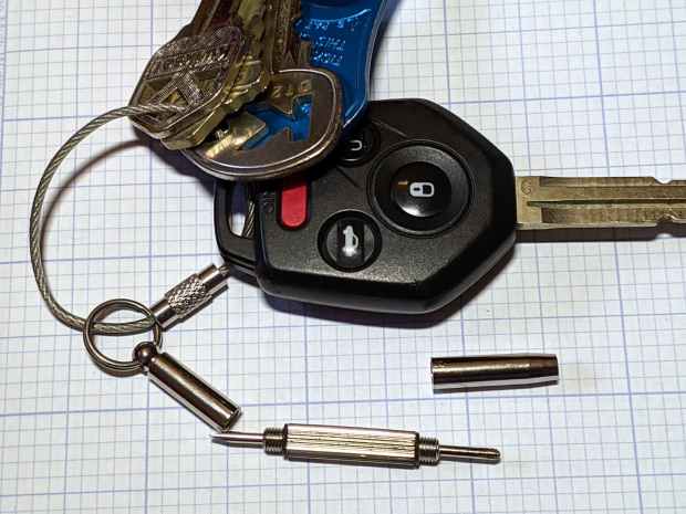
The far end has a 2.5 mm hex driver, although I’ve never encountered a nut for an M1×0.25 screw in the wild. It doesn’t fit an 0-80 nut and gulps 00-90 nuts, so it’s definitely hard metric.
My collection of glasses required an aggregate two turns of tightening, which prompted dBm to remind me of threadlock.
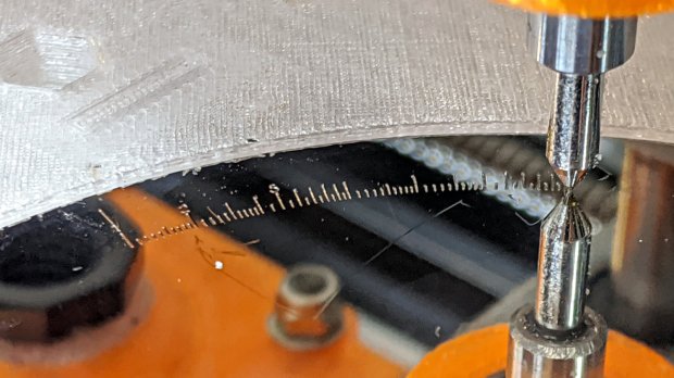
Engraving the Tektronix Circuit Computer bottom deck on a scrap hard drive platter suggested I’m entirely too much of a sissy about downforce on the diamond drag bit:
Tek CC – bottom deck – HD platter – L scale
That’s at Z=-5 mm for 350 g of downforce, with the spring preloaded with 100 g at a 50 g/mm rate. More or less, anyhow.
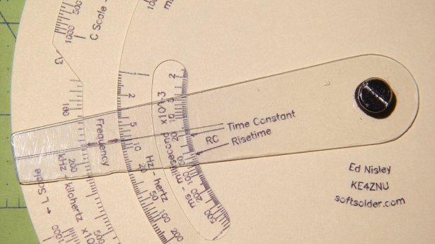
The GCMC code automagically scales everything by the ratio of the actual platter OD to the original Tek bottom deck. Using 93 mm for a hard drive platter (actual OD = 95 mm) sets the scaling to 0.197 = 93/197, which makes the scale legends just barely visible:
Tek CC – bottom deck – scaled to HD platter
The thing looks lovely, though, with ticks engraved at 2400 mm/min and the text at 2000 mm/min. The problem turns out to be the time taken to run the Z axis down and up while engraving so many ticks and characters!
I cranked on another 2 mm = 100 g of preload:
CNC 3018-Pro – diamond bit downforce plot
The top graph shows the downforce in 0.1 mm increments, rising from 0.0 to 217 g in 0.3 mm, which illustrates what the Y intercept of the plot means in real life.
Engraving at Z=-3 mm will now produce 350 g of downforce and cut the Z axis travel time down by a bit less than half. I have no idea what the right force might be; more experiments are in order.
Two passes make the scratch deep enough to hold engraving crayon / lacquer / ink, without making it much wider. Laser engraving would surely work better.
In lieu of actually milling the cursor, this code scratches the perimeter:
  local dr = DeckBottomOD/2;
  local hr = CursorHubOD/2;
  local a = atan(hr - CursorTipWidth/2,dr);   // rough & ready approximation

  local p0 = hr * [sin(a),cos(a),-];          // upper tangent point on hub

  local c1 = [dr - CursorTipRadius,CursorTipWidth/2 - CursorTipRadius*cos(a),-];
  local p1 = c1 + [CursorTipRadius*sin(a),CursorTipRadius*cos(a),-];

  local p2 = c1 + [CursorTipRadius,0,-];      // around tip radius

  feedrate(KnifeSpeed);

  goto([-,-,TravelZ]);
  goto([-hr,0,-]);
  move([-,-,EngraveZ]);

  repeat(3) {
    arc_cw(p0,hr);
    move(p1);
    arc_cw(p2,CursorTipRadius);

    move([p2.x,-p2.y,-]);
    arc_cw([p1.x,-p1.y,-],CursorTipRadius);
    move([p0.x,-p0.y,-]);
    arc_cw([-hr,0,-],hr);
  }
Three passes makes it deep enough to snap along the line:
Tektronix Circuit Computer – cursor outline
If you look closely, though, you’ll find a little divot over on the left along the bottom edge, so I really must machine the thing.
Were I to go into production, I’d have to figure out a fixture, but I think I can just clamp a rough-cut acrylic rectangle to the Sherline’s table, mill half the perimeter, re-clamp without moving anything, then mill the other half.
Subtractive machining is such a bother!
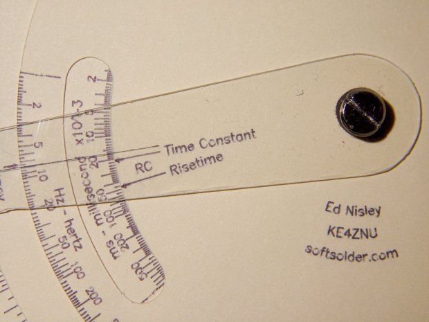
The pivot holding the cursor and decks together is a “Chicago screw“, a.k.a. a “sex bolt“. I am not making this up.
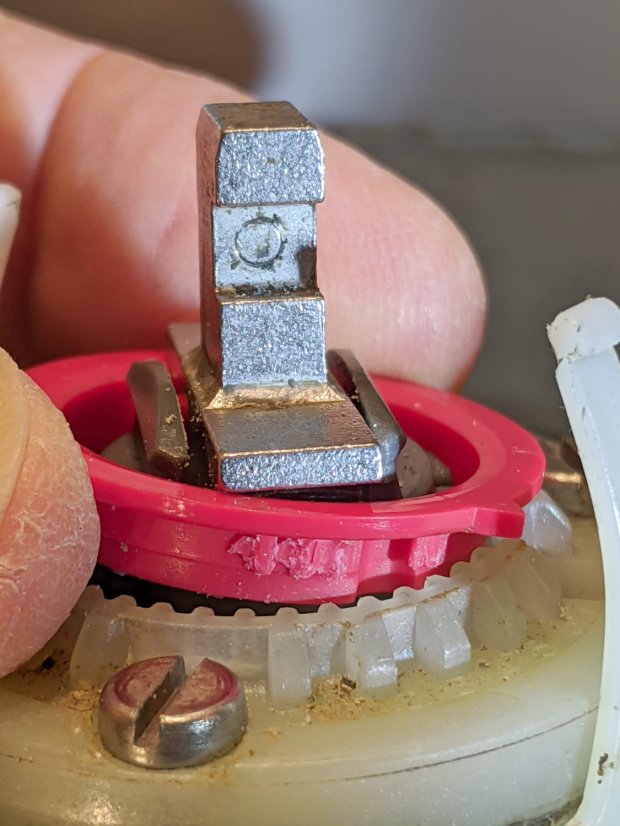
During an evening KP session, the kitchen faucet handle jammed at the clockwise (hottest) end of its travel and refused to turn; it continued to move vertically and I turned off the water. This had happened before, so I knew roughly what to expect:
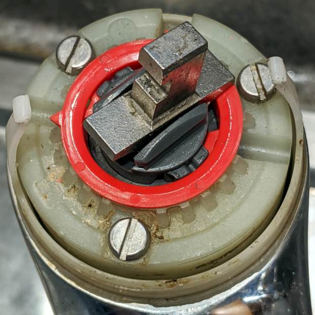
The pointer on the red hot limit safety stop ring should be aimed just right of the front screw, at the 0 position producing maximum hotness. The scale reads backwards, perhaps in units of increasing safety.
In that position, the ring prevents the valve core from turning counterclockwise, which explains the symptoms. With the water turned off (at the ball valves in the basement) and the valve stub tilted vertically, the ring popped loose (it shouldn’t move on its own) and exposed the problem:
Am Std Elite Faucet – wrecked hot limit splines – as found
Neither Mary nor I recall applying that much force to the handle, but ya never know.
The flanges protruding from the stem prevent you from removing the ring, but a pair of small diagonal cutters will chop right through the plastic. If you’re one of the six people depending on the limit stop to keep the water temperature under control, you probably don’t want to cut the ring out; I have no suggestions on how to repair it.
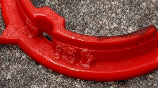
It’s obvious the splines won’t ever be the same again:
Am Std Elite Faucet – wrecked hot limit splines – detail 1
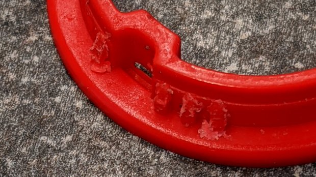
The ring has two sets of splines and they’re both wrecked:
Am Std Elite Faucet – wrecked hot limit splines – detail 2
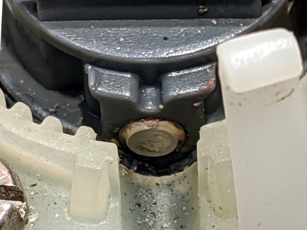
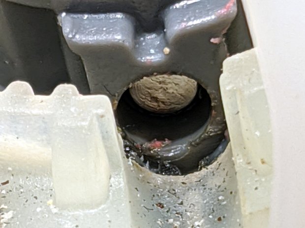
With the ring out of the way, it’s easy to see the trunnion shaft has moved leftward:
Am Std Elite Faucet – misaligned pivot shaft
There’s essentially no clearance between the shaft and the ring, so it was rubbing against the ring, as evidenced by the red debris left behind when I tapped it to the far end of its travel:
Reassemble in reverse order and it works fine again.
I expect the shaft will resume moving leftward and eventually jam in the notch, probably after abrading the white plastic, but I don’t see how to lock it in place.
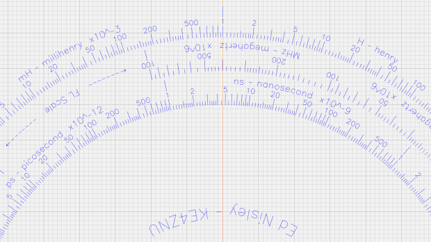
The Tektronix Circuit Computer, being a specialized circular slide rule, requires logarithmic scales bent around arcs:
Scale Tick Layout – Bottom Deck
Each decade spans 18°, except for the FL scale’s 36° span to extract the square root of the LC product:
FL = 1 / (2π · sqrt(LC))
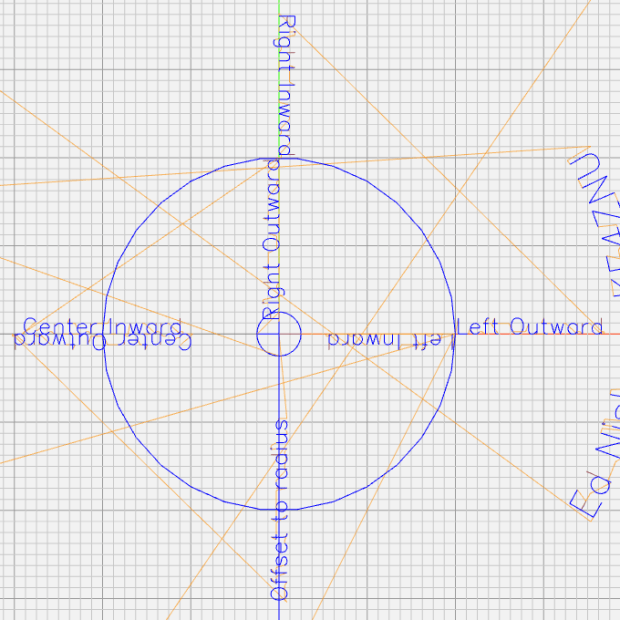
The tick marks can point inward or outward from their baseline radius, with corresponding scale labels reading either inward or outward.
There being no (easy) way to algorithmically set the tick lengths, I used a (pair of) tables (a.k.a. vector lists):
TickScaleNarrow = {
  [1.0,TickMajor],
  [1.1,TickMinor],[1.2,TickMinor],[1.3,TickMinor],[1.4,TickMinor],
  [1.5,TickMid],
  [1.6,TickMinor],[1.7,TickMinor],[1.8,TickMinor],[1.9,TickMinor],
  [2.0,TickMajor],
  [2.2,TickMinor],[2.4,TickMinor],[2.6,TickMinor],[2.8,TickMinor],
  [3.0,TickMajor],
… and so on …
The first number in each vector is the tick value in the decade, the log of which corresponds to its angular position. The second gives its length, with three constants matching up to the actual lengths on the Tek scales.
The Circuit Computer labels only three ticks within each decade in the familiar (to EE bears, anyhow) 1, 2, 5 sequence. Their logs are 0.0, 0.3, and 0.7, spacing them neatly at the 1/3 decade points.
Pop quiz: If you wanted to label two evenly spaced ticks per decade, you’d mark 1 and …
Generating the L (inductance) scale on the bottom deck goes like this:
The L scale covers 1 nH to 1 MH (!), as set by the MinLog and MaxLog values. Arc sets the angular size of each decade from ScaleArc, with the negative sign indicating the values increase in the clockwise direction.
The first decade starts with a tick labeled 1, so dec = 1. The next decade has dec = 10 and the third has dec = 100. Maybe I should have used the log values 0, 1, and 2, but that seemed too intricate.
The angular offset is zero because this is the outermost scale, so 1.0 H will be at 0° (the picture is rotated about half a turns, so you’ll find it off to the left). All other scales on the deck have a nonzero offset to put their unit tick at the proper angle with respect to this one.
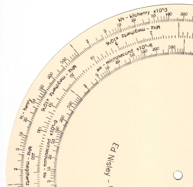
The scales have legends for each group of three decades, positioned in the middle of the group:
I wish there were a clean way to draw exponents, as the GCMC Hershey font does not include superscripts, but the characters already live at the small end of what’s do-able with a ballpoint pen cartridge. Engraving will surely work better, but stylin’ exponents are definitely in the nature of fine tuning.
With all that in hand, the scales look just like they should:
This file contains hidden or bidirectional Unicode text that may be interpreted or compiled differently than what appears below. To review, open the file in an editor that reveals hidden Unicode characters.
Learn more about bidirectional Unicode characters
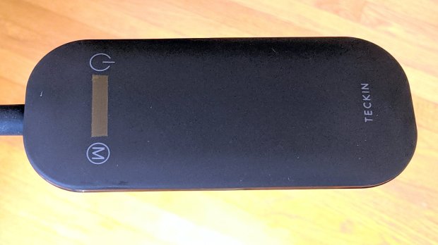
A new floor lamp arrived with the usual dark-gray-on-black annotations on an absolutely non-tactile pair of capacitive controls. For a device intended for use in a dim room, this makes little sense, unless you’re both trendy and concerned about manufacturing costs.
A strip of 1/4 inch Kapton tape added just enough tactility to find the damn buttons without looking at the lamp head:
Teckin floor lamp – tactile switch tape
The pole’s non-adjustable length put the lamp head well above eye level, so I removed one pole segment. This required cutting the 12 V zipcord and crimping a pair of connectors:
Teckin floor lamp – spliced wire
I briefly considered conjuring a skinny connector, but came to my senses: there’s plenty of zipcord if I must chop out the connectors, particularly seeing as how shortening the pole added a foot.
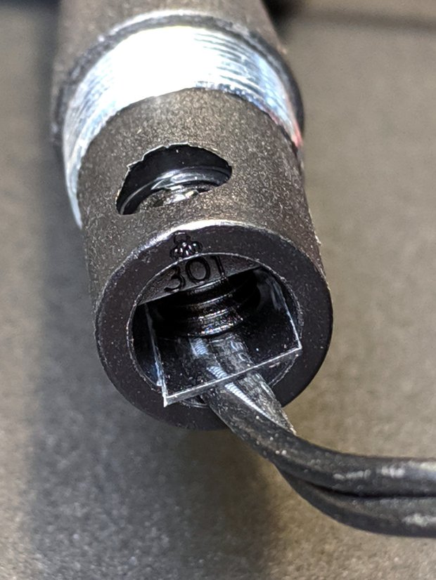
The setscrew at the bottom of the gooseneck crunched the zipcord against the metal shell. A polypropylene snippet made me feel better, even if it makes no difference:
This file contains hidden or bidirectional Unicode text that may be interpreted or compiled differently than what appears below. To review, open the file in an editor that reveals hidden Unicode characters.
Learn more about bidirectional Unicode characters
This file contains hidden or bidirectional Unicode text that may be interpreted or compiled differently than what appears below. To review, open the file in an editor that reveals hidden Unicode characters.
Learn more about bidirectional Unicode characters