The Smell of Molten Projects in the Morning

Ed Nisley's Blog: Shop notes, electronics, firmware, machinery, 3D printing, laser cuttery, and curiosities. Contents: 100% human thinking, 0% AI slop.

Category: Machine Shop

Mechanical widgetry

  • Maximum 3D Printing Speed

    Maximum 3D Printing Speed

    With everybody 3D printing masks these days, the question of “how fast can you print” came up on the Makergear forum.

    Here’s my opinion:

    The fundamental limit comes from the heater’s ability to bring cold plastic up to extrusion temperature inside the 20 mm hot zone.

    Using airscape’s example, the extruded thread is 0.5 mm thick × 0.8 mm wide = 0.4 mm², so laying down that thread at 50 mm/s means the extruder is heating plastic at 20 mm³/s and is “pushing it with PLA”.

    In round numbers, normal printing speeds with a normal nozzle and normal plastics runs around 10 mm³/s, so a practical upper limit is probably around 15 mm³/s.

    As far as thread size goes, the diameter of the flat area around the nozzle orifice sets the maximum thread width, because the nozzle must compress the thread against the previous layer. If the thread is wider than the nozzle, the gooey plastic curls up around the sides of the nozzle and doesn’t bond well. The rule of thumb is to round up the orifice diameter to the next convenient number:

    • 0.35 mm nozzle → 0.4 mm thread
    • 0.75 mm nozzle → 0.8 mm thread

    The maximum thread (= layer) thickness should be about 60% of the thread width, which is why a 0.8 mm wide thread calls for a 0.5 mm layer thickness.

    Assuming the extruder can heat 15 mm³/s of plastic, the maximum printing speed will be 15 mm³/s / 0.4 mm² = 37.5 mm/s: comfortably under airscape’s “pushing it” 50 mm/s.

    A visualization may be helpful:

    Extrusion Dimensions
    Extrusion Dimensions

    Aaaaand, as always, calibrate the Extrusion Multiplier for whatever conditions you’re using to ensure the slicer and the hardware agree on how much plastic is coming out of the nozzle.

  • Backyard Utility Pole: Anchor Clamp Hardware

    Backyard Utility Pole: Anchor Clamp Hardware

    This also appeared while clearing the forsythia:

    Pole anchor - abandoned in place
    Pole anchor – abandoned in place

    It’s the guy line anchor for the fallen utility pole, abandoned in place when the crew installed the new pole.

    The rod turned freely in its underground anchor, but the nut is apparently frozen to the rod. I deployed the bolt cutter on the cable and hauled the carcass into the Basement Shop:

    Pole anchor - nut loosening
    Pole anchor – nut loosening

    Steeping the nuts with Kroil for a few hours relaxed them enough to submit to gentle suasion, whereupon the cable sproinged as the last nut released the clamping force:

    Pole anchor - hardware
    Pole anchor – hardware

    As far as I can tell, the clamp hardware dates back to the pole’s original installation in 1940 and is in fine, if not pristine, shape.

    The bolt shanks have an oval section matching the holes in the plate, so the bolts don’t turn and the crew needs only one wrench. They don’t make ’em like they used to!

    I have no idea what I’ll do with these things, but they’re entirely too nice for the steel recycling bucket.

  • Tek Circuit Computer: Cursor Hairline Filling

    Tek Circuit Computer: Cursor Hairline Filling

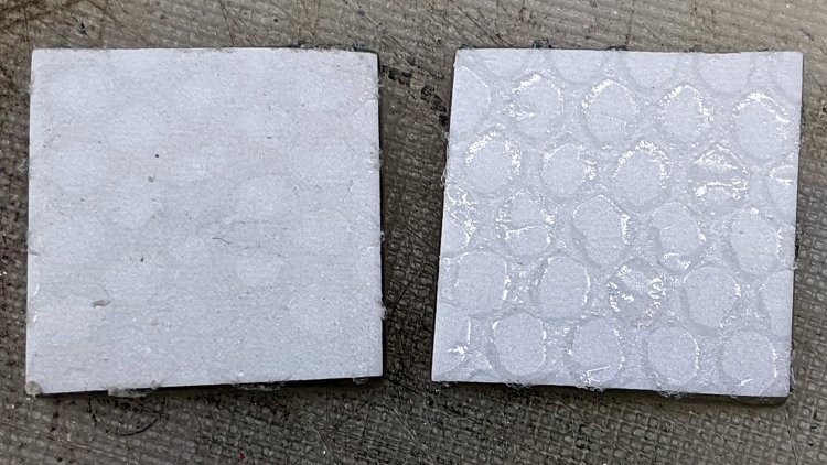
    Some cleanup and a fresh layer of double-sided tape gives the cursor milling fixture plenty of adhesion:

    Tek CC - Cursor blank on fixture
    Tek CC – Cursor blank on fixture

    This time, I diamond-scribed three PETG cursors through the transparent protective film, with two / four / six passes:

    Tek CC - Cursor hairline filling
    Tek CC – Cursor hairline filling

    It’s not a Purple Crayon, but it suffices for my simple needs.

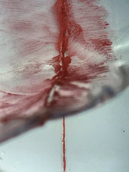
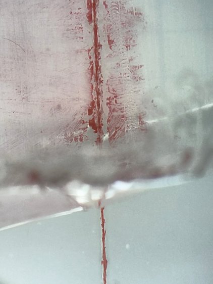
    Scribbling a (soft!) lacquer crayon over transparent plastic still scuffs the pristine surface around the engraved line, so I tried scribbling the six-pass cursor before peeling the film, as shown above. Unfortunately, the film shreds left around the line either prevent a clean fill or pull the paint out of the ditch as the film peels back:

    Tek CC - Cursor lacquer fill
    Tek CC – Cursor lacquer fill

    Peeling the film and scribbling ever-so-gently left a more complete line, but, if you look very closely (perhaps opening the image in a new tab for more dots), you can see the scuffs left by the scribbles on either side of the line:

    Tek CC - Cursor 2 4 6 scribes
    Tek CC – Cursor 2 4 6 scribes

    When seen from the other side against laminated decks, though, the scuffs pretty much vanish:

    Tek CC - Classic Tek Logo vectorized - red hairline
    Tek CC – Classic Tek Logo vectorized – red hairline

    The red hairline isn’t historically accurate, but I like the way it looks.

    Give me some (heavyweight matte) paper and a (lacquer) crayon, put me in a basement (shop), and I’ll be happy for days

  • Vectorized Classic Tektronix Logo

    Vectorized Classic Tektronix Logo

    The Tektronix Circuit Computer sports the most ancient of many Tektronix logos:

    Tek CC Logo - scanned
    Tek CC Logo – scanned

    It’s a bitty thing, with the CRT about 0.7 inch long, scanned directly from my original Tek CC.

    Import the PNG image into FreeCAD at 0.2 mm below the XY plane, resize it upward a smidge so the CRT is maybe 0.8 inch long, then trace “wires” all over it:

    Tek Logo - FreeCAD tracing - overlay
    Tek Logo – FreeCAD tracing – overlay

    Given FreeCAD’s default gradient background, the wires definitely don’t stand out by themselves:

    Tek Logo - FreeCAD tracing - vectors
    Tek Logo – FreeCAD tracing – vectors

    Several iterations later, the vectorized logo sits at the correct angle and distance from the origin at the center:

    Tek Logo - FreeCAD tracing - rotated
    Tek Logo – FreeCAD tracing – rotated

    The cheerful colors correspond to various “groups” and make it easier to find errant vectors.

    Rather than figure out how to coerce FreeCAD into converting wires into proper G-Code, export the vectors into a DXF file and slam it into DXF2GCODE:

    Tek Logo - DXF2GCODE vectors
    Tek Logo – DXF2GCODE vectors

    Export as G-Code, iterate around the whole loop a few times to wring out the obvious mistakes, indulge in vigorous yak shaving, eventually decide it’s Good Enough™ for the moment.

    Protip: set DFX2GCODE to put “0” digits before the decimal point to eliminate spaces between the coordinate axes and the numeric values which should not matter in the least, but which confuse NCViewer into ignoring the entire file.

    Tinker the script running the GCMC source code to prepend the logo G-Code to the main file and it all comes out in one run:

    Tek CC - with vectorized logo - cutting
    Tek CC – with vectorized logo – cutting

    That’s the top deck, laminated in plastic, affixed to a Cricut sticky mat on the MPCNC platform, ready for drag-knife cutting.

    Assembled with a snappy red hairline:

    Tek CC - Classic Tek Logo vectorized - red hairline
    Tek CC – Classic Tek Logo vectorized – red hairline

    Isn’t it just the cutest thing you’ve seen in a while?

    It needs more work, but it’s pretty close to right.

  • Homage Tektronix Circuit Computer: Minimally Viable Product, Pickett Variation

    Homage Tektronix Circuit Computer: Minimally Viable Product, Pickett Variation

    This one came out just about perfect:

    Tek Circuit Computer - MVP - Pickett Edition - front
    Tek Circuit Computer – MVP – Pickett Edition – front

    The yellow decks may not be authentic, but they definitely look nice; think of it as an homage to Pickett’s Eye-Saver Yellow slipsticks.

    The rear has my how-to-operate hints:

    Tek Circuit Computer - MVP - Pickett Edition - back
    Tek Circuit Computer – MVP – Pickett Edition – back

    Laser-printing on “inkjet” paper worked fine, although this isn’t fancy Gloss-coated Brochure paper, and the text looks like it should.

    The cursor sports a two-pass hairline scribed at 330 g and filled with Lacquer-Stick paint:

    Tek CC - Milled PETG cursor - Lacquer-Stik hairline
    Tek CC – Milled PETG cursor – Lacquer-Stik hairline

    This time, I had the clear film on top!

    Although the picture doesn’t do it justice, the scales are in blue ink, which looks better against the yellow background. I suppose I could do custom colors:

    Pilot V5RT cartridge - ink levels
    Pilot V5RT cartridge – ink levels

    The line width has decreased as the ink level drops: 0.3 mm on yellow card stock and 0.2 mm on glossy white brochure paper. I don’t know if they’re supposed to work like that, but, for this application, narrower lines are definitely better.

  • Tek Circuit Computer: Paper Matters, Redux

    Tek Circuit Computer: Paper Matters, Redux

    The back of a Tektronix Circuit Computer’s bottom deck carries instructions and information:

    Tektronix Circuit Computer - rear
    Tektronix Circuit Computer – rear

    A separate instruction manual told you how to use the thing, under the reasonable assumption you’d be intimately familiar with slide rules.

    In this day and age, the back should carry how-to-use instructions, so I summarized the manual into half a dozen lists:

    Tek CC - instructions - first pass
    Tek CC – instructions – first pass

    Which looked fine & dandy & ready to print, thereby exposing various typos / inconsistencies / misalignments:

    Tek CC - test print - HP Brochure vs ordinary copy paper
    Tek CC – test print – HP Brochure vs ordinary copy paper

    Whereupon I (re)discovered just how much paper matters.

    The HP Brochure Glossy inkjet paper on the left produces wonderful results with a 0.5 mm Pilot V5RT ball point pen and has coating on both sides. It’s intended for handouts, brochures, and suchlike; the Pilot pens produce identical results on either side.

    The same text, printed on plain old 22 pound “multipurpose” paper on the right, looks much better and makes the HP paper looks like something done with crayon on paper towel.

    I could try a font with finer strokes, but … ick.

    It’s unclear whether Brochure Matte paper would make any difference, nor whether running coated “inkjet” paper through a laser printer would have an … infelicitous … outcome.

    Past experience shows the unsteady ziggurat of Linux printing doesn’t respond well to tweakage: when the default settings don’t work, there’s no easy / predictable way to change any particular setting.

    For future reference, print the instruction on what will become the back of the bottom deck, mark the center point, tape it to the CNC 3018 platform, touch off XY = 0 at the center, and draw the front scales: everything lines up perfectly without extra fuss & bother.

  • PETG Diamond Drag Engraving Tests

    PETG Diamond Drag Engraving Tests

    The hairline on the second machined cursor looks pretty good:

    Tek CC - Milled cursor - unlaminated bottom deck
    Tek CC – Milled cursor – unlaminated bottom deck

    Based on manually scratching some acrylic, the GCMC code retraced the hairline four times to help the Sharpie stick to the groove. Maybe fewer passes would be better?

    Affix a PETG scrap to the milling fixture for some manual CNC action:

    PETG - engrave through film
    PETG – engrave through film

    Just to see what happened, I made the first scratch through the protective film and, because it’s hard to tell which side is up, the scratch went through the white film.

    Repeat several times with variations in number of passes & downforce:

    PETG - engraving test - overview
    PETG – engraving test – overview

    Manual jogging FTW:

    • 2 passes, 300 g, through film
    • 2 passes, 300 g, no film
    • 1 pass, 300 g
    • 3 passes, 300 g
    • 4 passes, 300 g
    • 1 pass, 260 g
    • 1 pass, 330 g

    A closer look through the PETG sheet, as you’d see finished hairline, with the scratches in the same order as above:

    PETG - engraving test - detail grid
    PETG – engraving test – detail grid

    They may be easier to see against a blank background:

    PETG - engraving test - detail plain
    PETG – engraving test – detail plain

    Or in a hairline’s natural environment:

    PETG - engraving test vs Testors sample
    PETG – engraving test vs Testors sample

    The absolute best-looking line is at the top, with the diamond point scribing through the (white) protective plastic film.

    Multiple passes average out the waves / glitches / irregularities, at the cost of broadening the hairline.

    The bottom hairline suggests a single pass with more downforce produces a broader groove and a finer line of Sharpie ink at the bottom; the top appears more rounded and the bottom more ragged.

    Doing one pass with enough pressure to cut through the thinner (?) transparent(-ish) film may produce a better overall result. This will require me to get the orientation right.

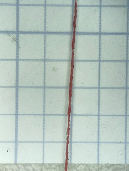
    The Real Hairline in my K&E Deci-Lon slipstick is a smoothly engraved, neatly half-cylindrical, channel with a smooth thread of red (!) ink / paint / pigment laid along the middle. Obviously, my engraving hand is weak …

    The nightmare scenario: engraving a smooth hairline groove, completely backfilling it with paint, sanding (that side of) the cursor smooth to leave the groove’s paint flush with the surface, then polishing the plastic back to full transparency. Even I agree that’s crazy talk, at least for a circular slide rule made with laminated paper decks.