Ed Nisley's Blog: Shop notes, electronics, firmware, machinery, 3D printing, laser cuttery, and curiosities. Contents: 100% human thinking, 0% AI slop.
After fartoomanyrepairs, we bought a new Brita pitcher with slightly different, although apparently equally crappy, hinge pins, whereupon I bandsawed the long-failed “smart” filter timer out of the old pitcher’s lid:
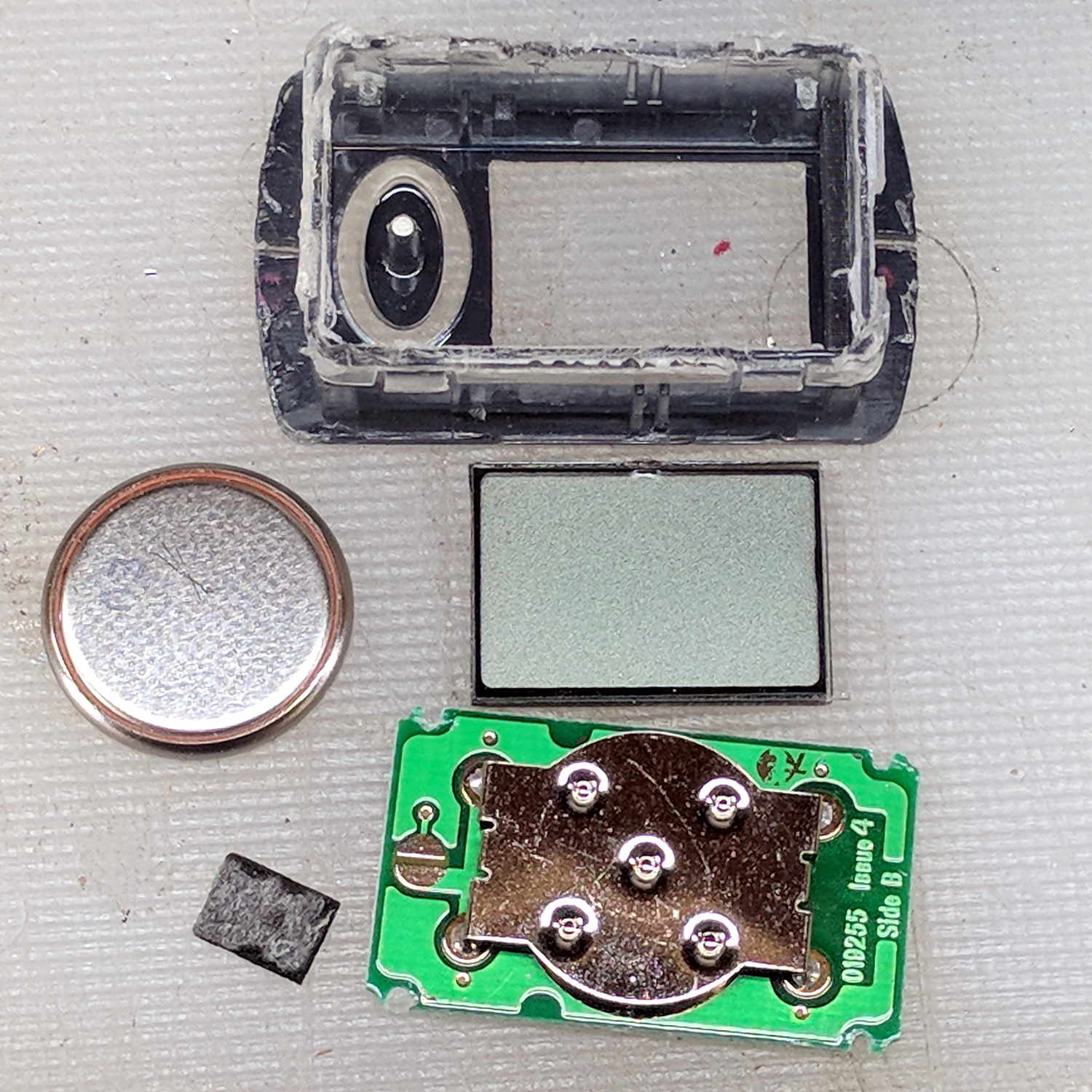
Brita pitcher timer – contents
The gray rectangle is the LCD panel showing how long since you last replaced the filter. It died some years ago and, indeed, the CR1616 battery was down to 2.8 V.
However, I think the real failure happened when the black square of conductive foam slipped off the switch contacts under the Reset pushbutton’s stud and went walkabout inside the timer:
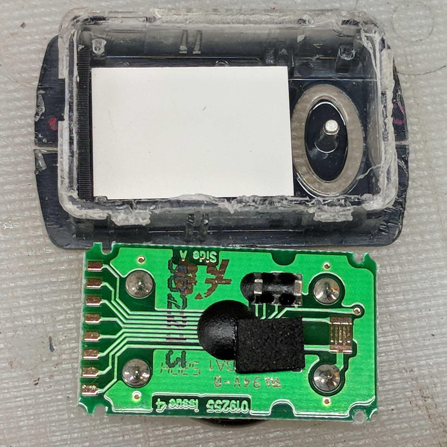
Brita pitcher timer – opened
That’s where I found it after sawing the casing open. I think the adhesive side should be stuck to the stud, but we’ll never know.
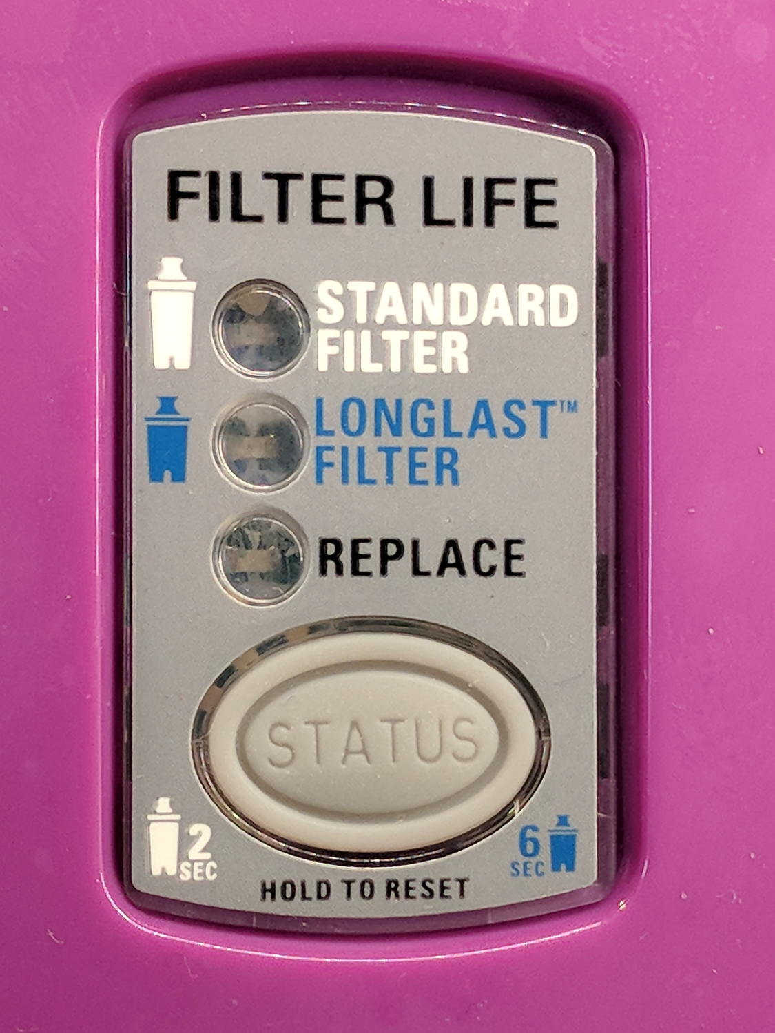
The new pitcher includes a different indicator with green LED status blinkies for “Standard” (40 gallon) and “Longlast” (120 gallon) filter cartridges and a red blinkie for “Expired”:
Brita pitcher – Filter Life counter
Yeah, purple. For some unknown reason, it cost 10% less than the other colors and we’re not fussy.
This one measures filter use by water volume, not elapsed time, counting the number of pitcher refills by noticing when you open the flip-top lid; the corresponding volume depends on your ability to see a nearly invisible line molded into the lid. Unsurprisingly, Longlast filters cost only slightly less than three times standard ones, so they’re not a compelling value proposition.
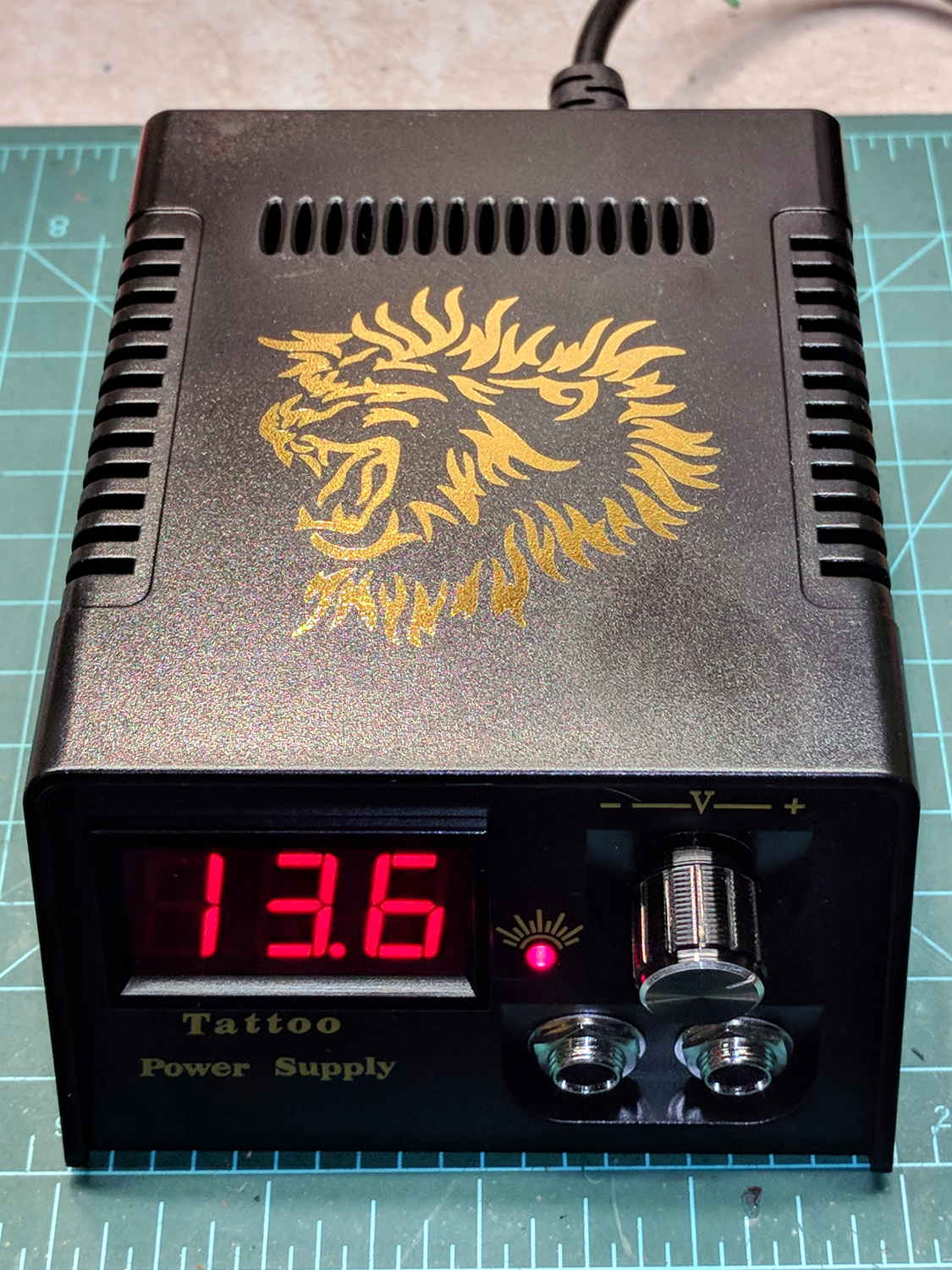
The gold lion really spiffs up the Electronics Workbench!
Somewhat to my surprise, the circuit uses a switching power supply based on a Reactor Micro RM6302 controller that can produce about an amp at voltages up to about 14 V:
Tattoo Digital Power Supply – internal view
CAUTION: Everything on the input side of the transformer runs at line potential. I have my doubts about isolation, particularly under fault conditions.
The trimpot on the PCB seems to adjust the output voltage, although it’s not clear what’s going on.
The three wire AC line cord has a standard IEC entry block on the rear panel, albeit with the ground terminal not connected to anything inside the plastic case. It arrived with the hot wire soldered to a tiny fuse on the PCB and the neutral wire (red!) to the back-panel switch. There being no practical way to put the fuse before the switch, I rewired the hot side to the switch before the fuse and the unswitched neutral to the PCB; that’s as good as it’ll get.
I also flipped the AC switch to put the ON position at the top. Sheesh.
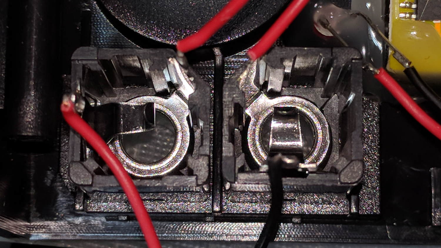
The two 1/4 inch jacks on the front panel are wired in series, so it didn’t matter which one got the tattoo needler or the foot switch:
Tattoo Digital Power Supply – jacks in series
I rewired the sockets in parallel to eliminate the need for a shorting plug, although I cannot imagine any need for two outputs.
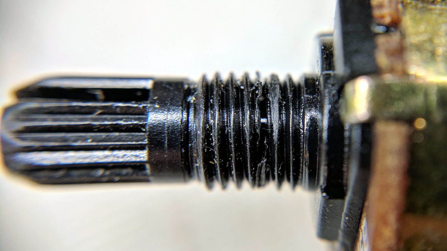
The knob seemed unusually sloppy, which turned out to be due to a broken threaded sleeve around the pot shaft that prevented the crudely made nut from seating tightly:
Tattoo Digital Power Supply – broken pot threads
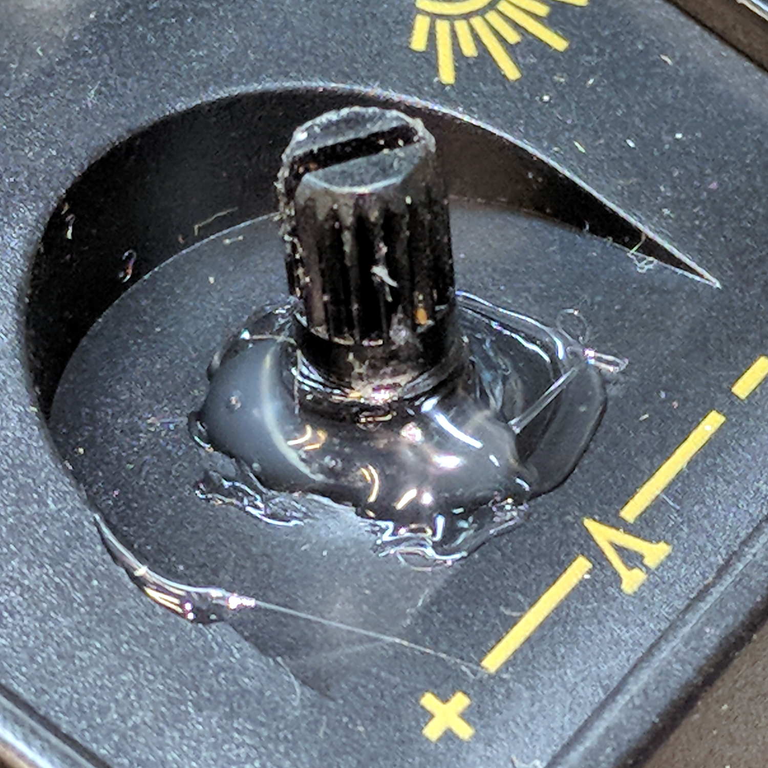
Given that the builders stuck everything else to the front panel with hot-melt glue, I followed suit:
Tattoo Digital Power Supply – glued pot threads
Which actually held it in place reasonably well, despite the hideous appearance. The knob covers the blob, so It Doesn’t Matter.
The output range extends from about 1.2 V to just over 14 V at about an amp, but the knob seems erratic and the digital meter has only a casual relationship to the actual output voltage.
I think if you regard this one as a parts kit, reverse-engineer the schematic (which surely descends directly from the RM6302 datasheet), and rebuild the electronics, it might work better.
Bottom line: The analog version seems to be better as a low-budget power supply, not least because it has a metal case and an actual power transformer for galvanic isolation.
Three times is enemy action, but we’re not there yet. I was willing to believe something I’d done had killed both of the radios, even though it seemed unlikely for them to last five years and fail almost simultaneously.
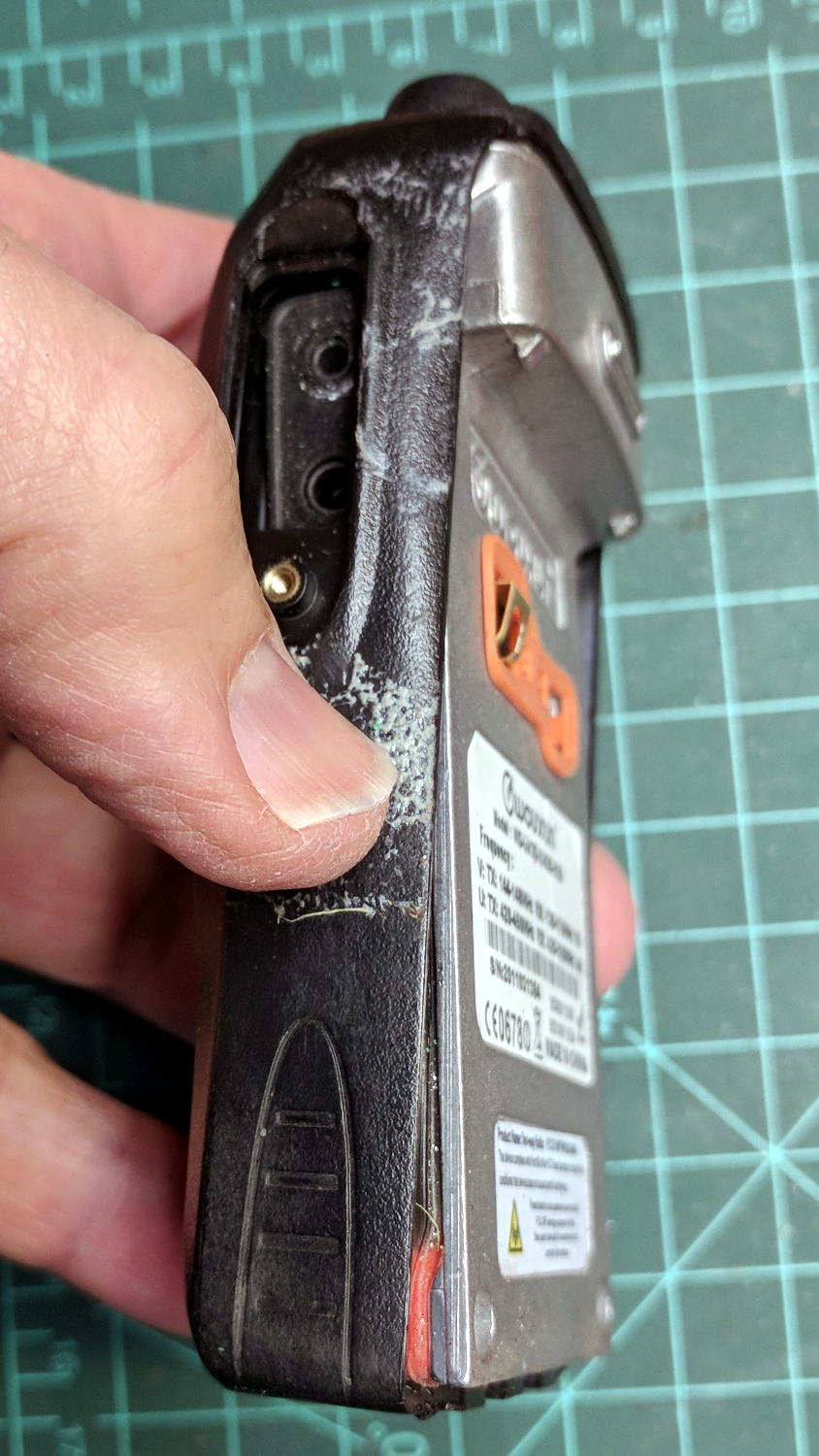
So I dismantled this one to see what’s inside. Pull off both knobs, remove the two screws at the bottom of the battery compartment, pry gently with a small screwdriver, and the whole PCB pulls out:
Wouxun KG-UV3D – disassembly
A bit more prying separates the big pieces:
Wouxun KG-UV3D – interior
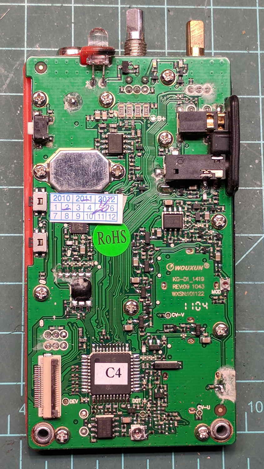
Looking closely at the main PCB showed some problems I definitely didn’t cause:
Wouxun KG-UV3D – PCB overview
Although it’s been riding around on my bike, the white blotches on the PCB came from inadequate flux removal after hand soldering.
A collection of images taken through the microscope reveals the problems:
This slideshow requires JavaScript.
I swabbed off the crud with denatured alcohol to no avail. The bottom side of the PCB has even more components and, I’m sure, even more crud, but I didn’t bother removing all the screws required to expose it, nor did I dismantle the other failed HT.
I doubt Wouxun’s QC improved over the last few years, which means the two replacement KG-UV3D radios I just bought are already on their last legs, despite my paying top dollar to the same reputable source that sold me the first pair.
We’ll be ready for new radios on new bikes by the time these fail.
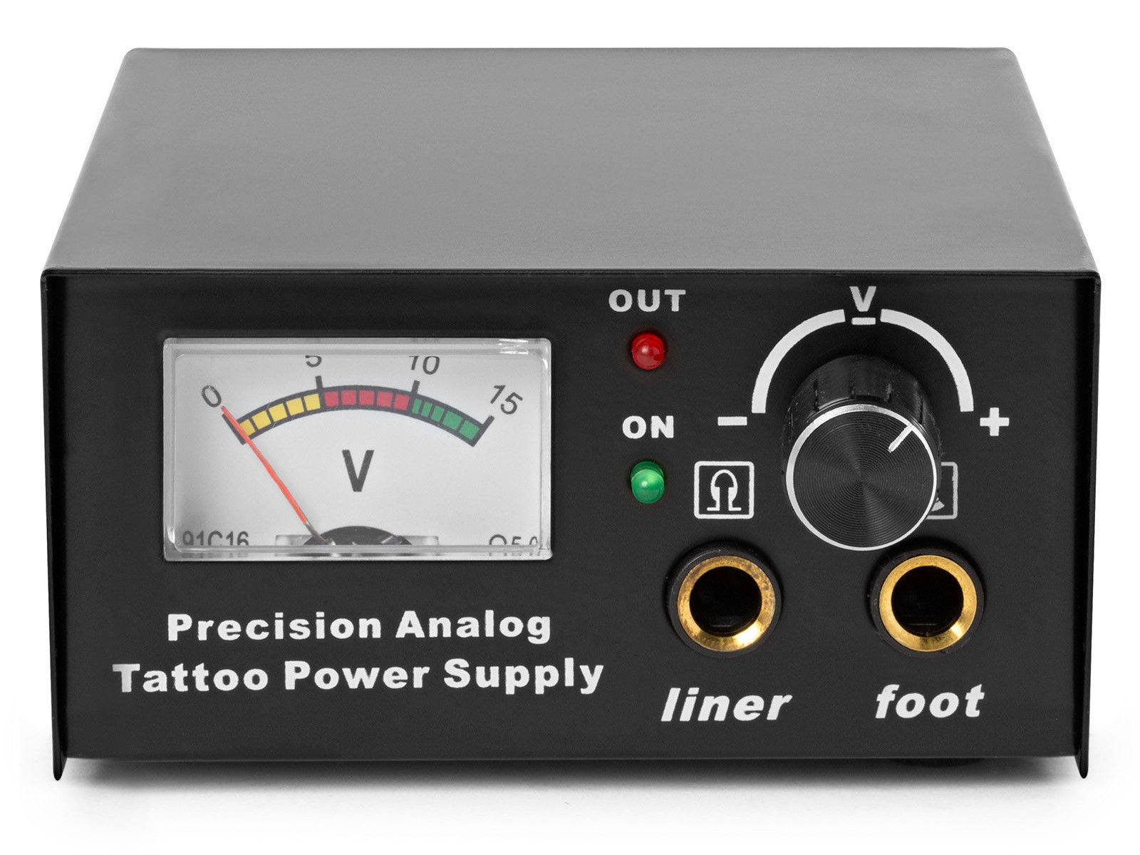
The idea behind this gadget surfaced while I was looking for something else and, although the front panel makes my skin crawl, it’s just an adjustable DC power supply:
Let’s say it has the potential to be a DC power supply, although we might quibble about the “Precision” part.
As delivered, it’s a deathtrap. Of course, it’s not UL listed and I didn’t expect it to be.
How many lethal problems do you see?
Tattoo power supply – original AC wiring
For starters, it has a three-wire AC line cord with the green-and-yellow conductor chopped off flush with the outer insulation inside the heatshrink tubing just behind the transformer:
Tattoo power supply – ungrounded AC line
The blue wire is AC neutral, but it really shouldn’t be connected to the finger-reachable outer fuse terminal.
The brown wire is AC line, which goes directly to one power switch terminal. In the event of a hot wiring fault, an unfused conductor touching the case will test the GFI you should have on your bench wiring.
The AC line cord uses some mysterious copper-colored metallic substance that’s about as stiff as music wire:
Tattoo power supply – stiff AC wire
The strands cannot be twisted together like ordinary copper wire, although they can be soldered. They may be copper-plated aluminum, because a magnet ignores them.
After soldering the strands together, they snap when bent:
Tattoo power supply – soldered broken AC wire
Generous strain relief is not just a good idea, it’s mandatory.
After some Quality Shop Time, the ground wire now connects to the case through the transformer’s rear mounting screw, the neutral AC wire connects to the transformer, the hot AC wire goes to the tip of the line fuse, and the fuse cap terminal goes to the switch:
Tattoo power supply – AC line rewiring
I relocated the white LED to the middle of the meter, where it looks a bit less weird:
Tattoo power supply – revised front panel
I have no idea what “Porket indicate” might mean. Perhaps “Precision indicator”?
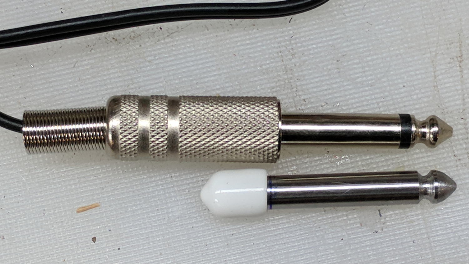
The right 1/4 inch jack, labeled “Foot”, normally goes to a foot switch you don’t need for a bench power supply, so I converted a length of drill rod into a dummy plug to short the jack contacts:
Tattoo power supply – dummy switch plug
The tip comes from a bit of lathe and file work and the white cap comes from a bag of wire shelf hardware.
A genuine hologram sticker (!) on the back panel proclaims “1.5 – 15 VDC 2 A”, which seemed optimistic. Some fiddling with power resistors suggests tattoo liners (I learned a new word!) don’t draw much current:
4 V @ 1 A
8 V @ 800 mA
10 V @ 600 mA
It can reach a bit over 18 V (pegging the meter) at lower current, so it’s Good Enough for small projects with un-fussy power requirements.
When I wired up the MPCNC’s tool length probe, I planned to reinforce the wiring with a dab of epoxy. What I didn’t notice in my enthusiasm, alas, was the opening from the rear to the front in each pin slot:
Epoxied connector – rear
Which let the epoxy flow completely through the connector:
Epoxied connector – front
So I cut the mess off and applied heatstink tubing on each wire, just like I should have in the first place.
Now you know the rest of the story …
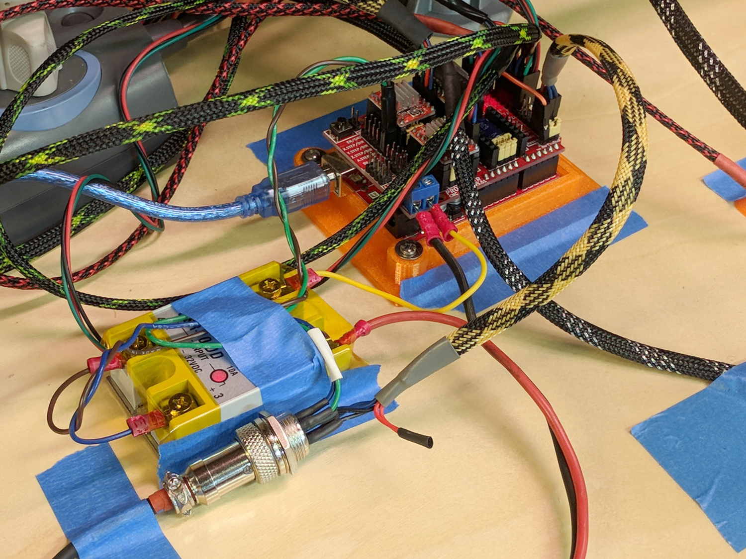
I really dislike pin headers as cable connectors, but that’s what the Protoneer CNC board uses:
MPCNC – Protoneer Wiring – SSR
It’ll be Good Enough if I don’t do anything else particularly stupid.
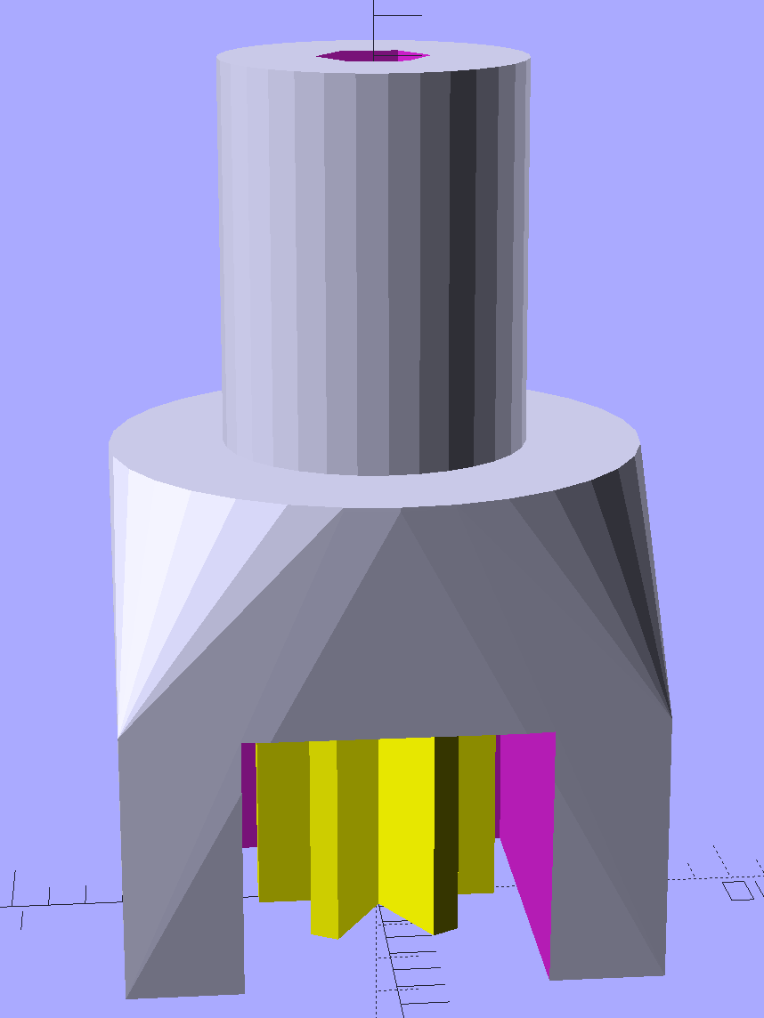
A little support pillar makes a printable holder for a small tactile pushbutton:
Z Axis Height Probe – solid model
A(n) 0-80 brass washer epoxied atop the butt end of a P100-B1 pogo pin keeps the pin from falling out and provides a flat button pusher:
MPCNC – Simple Z probe – push plate
With the epoxy mostly cured, ease the pin off the tape, flip the whole affair over, shove the switch into position, realign vertically with point down, then let the epoxy finish curing with the washer held in place against the switch to ensure good alignment:
MPCNC – Simple Z probe – epoxy curing
The brass tube ID is a sloppy fit around the pogo pin, but it’s also many pin diameters long and the position error isn’t worth worrying about.
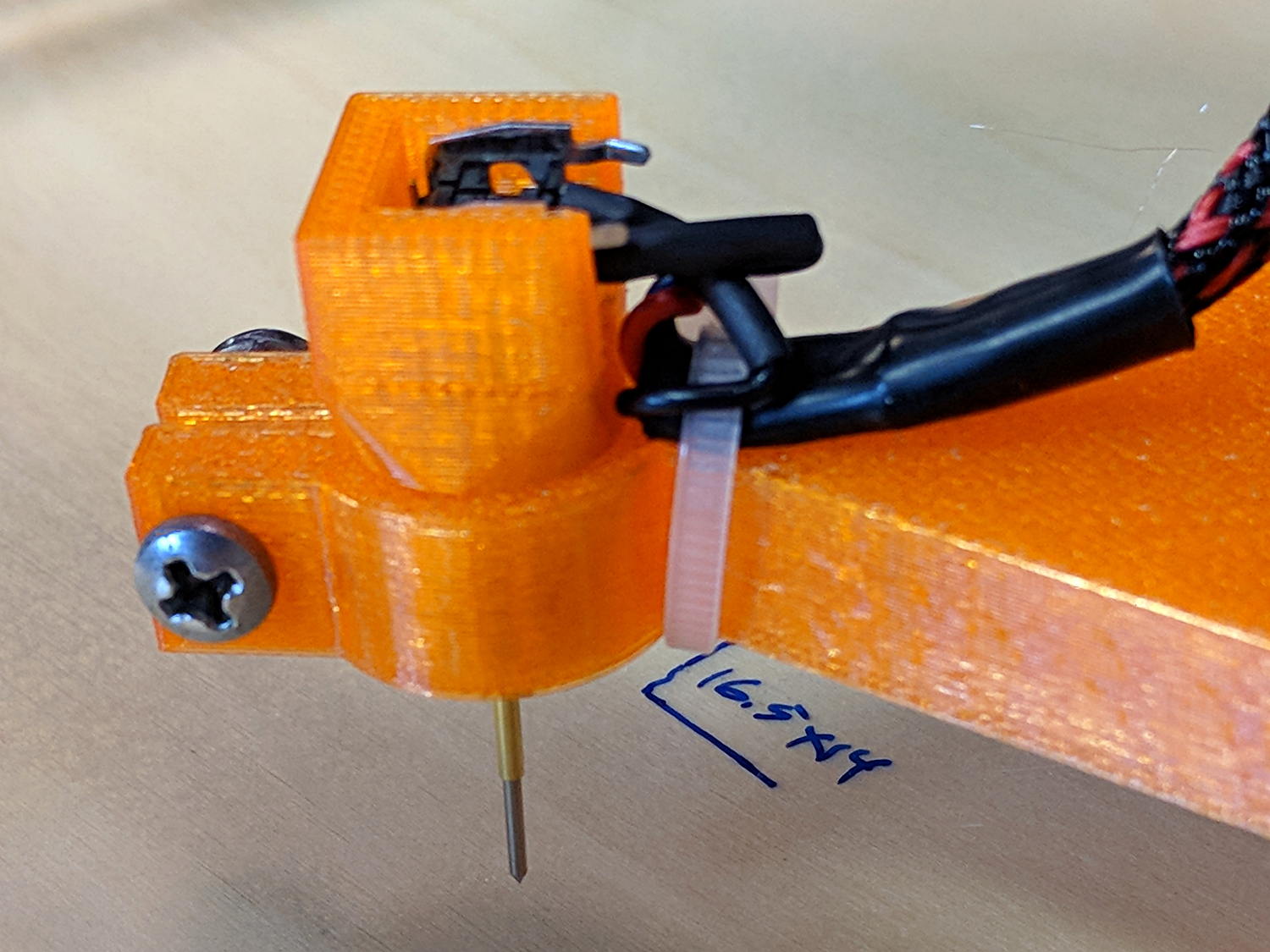
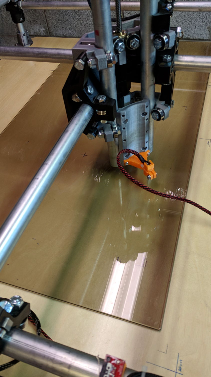
Solder a cable, clamp it in the pen holder, attach to tool holder:
MPCNC – Simple Z probe – installed
The pogo pin provides half a dozen millimeters of compliance, letting the initial probe speed be much higher than the tactile pushbutton’s overshoot could survive, after which a low-speed probe produces a consistent result.
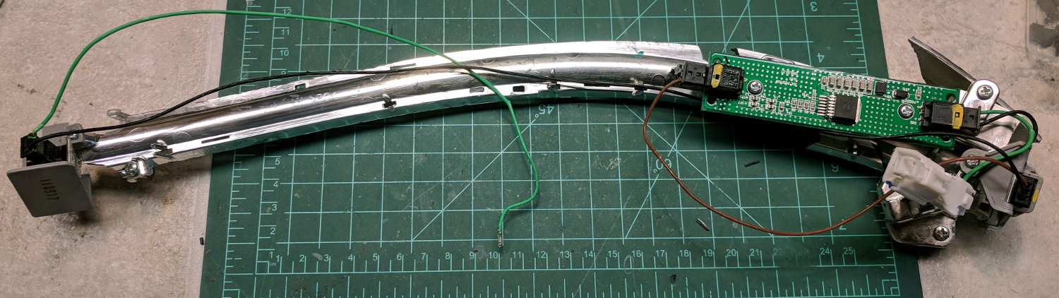
A high energy collision / accident / mishap in front of Adams Fairacre Farms (a.k.a., the grocery store) demolished 20 feet of their dry laid stone wall along Rt 44, flattened several bushes, gouged trenches in the grass, and scattered plastic debris into the parking lot. The remains of a headlight eyebrow running light emerged from a snow pile:
Eyebrow light – front
From the back:
Eyebrow light – back
Contrary to what I expected, it has one white LED at each end of the chromed reflecting channel, topped with a shaped plastic lens collecting the light:
Eyebrow light – Lens mount
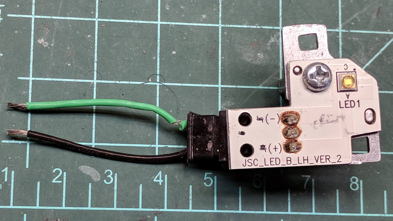
The LED PCBs are in series, which produced a backwards wire color code on one end:
Eyebrow light – LED PCB 1
The other end looked more reasonable:
Eyebrow light – LED PCB 2
The white SMD LEDs draw 300+ mA at 3.6 V, so they’re obviously depending on external current limiting provided by the regulator PCB, sporting a TLE4242 linear current regulator and a handful of passives:
Eyebrow light – Regulator PCB
AFAICT, they didn’t use the chip’s PWM control input or its LED failure status output.
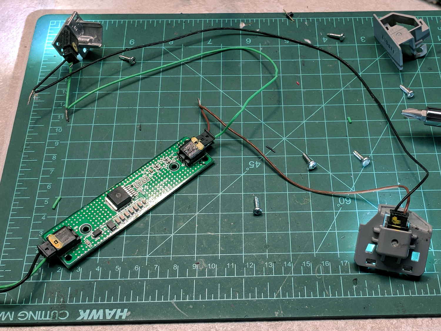
Extracting the various PCBs from the wreckage and reconnecting the wires produced a satisfactory result:
Eyebrow light – resurrection
The regulator limits the LED current to 120 mA at any input from a bit over 7 V to well past 12 V, with each LED dropping 3.0 V.
Dunno what I’ll use this junk for, but at least I know a bit more about eyebrow lights. The chip date codes suggest 2010 and 2012; perhaps linear regulators have become passe by now.