Having a tool length probe station on the Sherline, I had to build one for the MPCNC:
It’s little more than a flange atop a wide base:
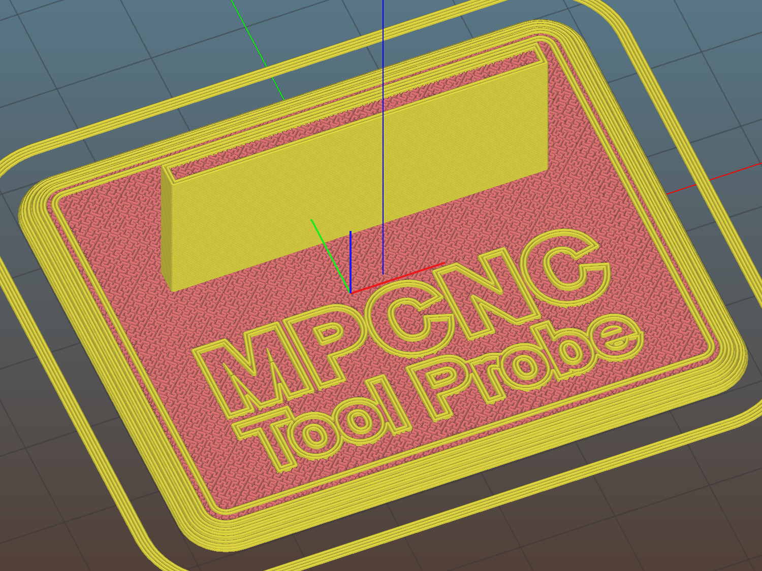
The flange offset puts the switch actuator on the midline of the base, not that that matters, and the base features rounded corners and a suitable legend, because I can.
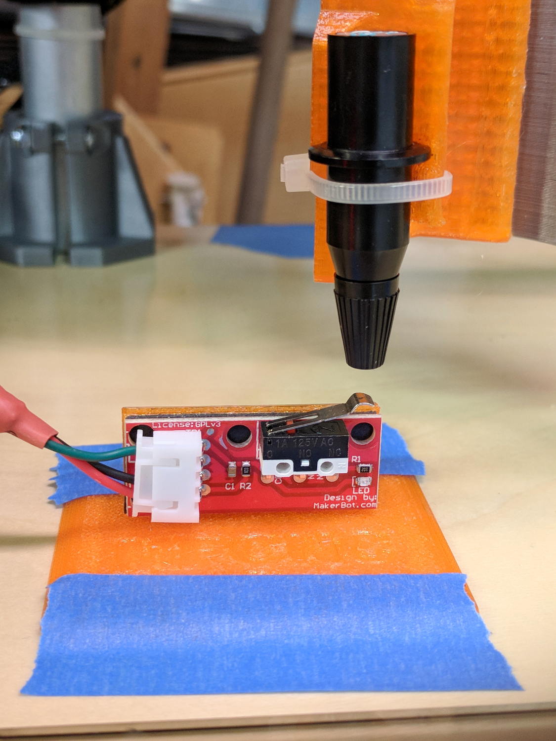
I clipped the PCB’s through-hold leads nearly flush and stuck it to the flange with 3M permanent foam tape, which seems to work much better than screws & inserts for simple things that need never come apart.
The Protoneer CNC Shield includes a Probe input on the GRBL-compliant A5, although it took me a while to find the legend on the SCL pin in the I2C header. I moved the endstop power jumper to another header, then conjured a quick-and-dirty connector:

When I embed the endstop switch PCB in epoxy, I’ll add a drop to the connector while engaging in Magical Thinking. The whole Arduino + CNC Shield must go into an enclosure after I finish measuring the motor currents.
To forestall discussions about switch repeatability and accuracy, suffice it to say the MPCNC doesn’t claim to be much more than a woodworking router, so those switches seem Good Enough.
The OpenSCAD source code as a GitHub Gist:
| // MPCNC Tool Length Probe Station | |
| // Ed Nisley KE4ZNU – 2017-12-08 | |
| /* [Extrusion] */ | |
| ThreadThick = 0.25; // [0.20, 0.25] | |
| ThreadWidth = 0.40; // [0.40] | |
| function IntegerMultiple(Size,Unit) = Unit * ceil(Size / Unit); | |
| /* [Hidden] */ | |
| Protrusion = 0.1; // [0.01, 0.1] | |
| HoleWindage = 0.2; | |
| /* [Sizes] */ | |
| EndstopPCB = [40.0,16.5,1.6]; // endstop PCB | |
| ComponentHeight = 6.0; // max component height above PCB | |
| SwitchOffset = [35.0,21.0,4.75]; // touch point center from lower left PCB corner | |
| SwitchTravel = 2.5; // first touch to switch actuation | |
| TapeThick = 1.0; // foam mounting tape | |
| WallThick = 4.0; // basic wall & floor thickness | |
| BaseRadius = 5.0; | |
| Base = [IntegerMultiple(EndstopPCB[0] + 2*BaseRadius,20), | |
| IntegerMultiple(EndstopPCB[2] + TapeThick + WallThick + 2*BaseRadius,2*25), | |
| 2.0]; | |
| NumSides = 8*4; | |
| TextDepth = 2*ThreadThick; | |
| //- Build it | |
| union() { | |
| difference() { | |
| hull() | |
| for (i=[-1,1], j=[-1,1]) | |
| translate([i*(Base[0]/2 – BaseRadius),j*(Base[1]/2 – BaseRadius),0]) | |
| resize([0,0,Base[2]]) | |
| intersection() { | |
| cylinder(r=BaseRadius,h=BaseRadius,$fn=NumSides); | |
| sphere(r=BaseRadius,$fn=NumSides); | |
| } | |
| translate([0,0,Base[2] – TextDepth]) | |
| linear_extrude(height=TextDepth + Protrusion) { | |
| translate([0,-10,0]) | |
| text(text="MPCNC",size=8,spacing=1.05,font="Arial:style=Bold",halign="center"); | |
| translate([0,-18,0]) | |
| text(text="Tool Probe",size=6,spacing=1.05,font="Arial:style=Regular",halign="center"); | |
| } | |
| } | |
| translate([0, | |
| WallThick/2 + TapeThick + SwitchOffset[2], | |
| (EndstopPCB[1] – Protrusion)/2 + Base[2]]) | |
| cube([EndstopPCB[0],WallThick,EndstopPCB[1] + Protrusion],center=true); | |
| } |
The original doodles show a severely over-complexicated solution desperately searching for an actual problem:

Putting a large flat pan at the end of a relatively long lever arm, with the pivot arranged to put the pan level at the switch actuation point, made sense at the time. Give the relatively small tools I expect to use, directly ramming them into the switch lever should work just as well.
Putting all that complexity in harm’s way seemed like a Bad Idea when I sat down and looked at it in cold blood.

Comments
6 responses to “MPCNC: Tool Length Probe Station”
I’d be more worried about adhesive tape flowing over time – some of them tend to move when force is biased only in one direction over long time.
The cable really should pass through a strain relief anchor, but the tape is allegedly good for mounting relatively heavy stuff on walls. If the PCB pops off, I’ll be both mightily disappointed and completely unsurprised.
[…] It turns out old-school plotter pen nibs skid right off the rounded top of the switch lever: […]
[…] I wired up the MPCNC’s tool length probe, I planned to reinforce the wiring with a dab of epoxy. What I didn’t notice in my […]
[…] that picture, I clipped off the NC switch terminal so I can wire this endstop in parallel with the tool length probe. Epoxy coating to […]
[…] a lever-arm switch as a tool length probe works surprisingly […]