The Smell of Molten Projects in the Morning

Ed Nisley's Blog: Shop notes, electronics, firmware, machinery, 3D printing, laser cuttery, and curiosities. Contents: 100% human thinking, 0% AI slop.

Category: Electronics Workbench

Electrical & Electronic gadgets

  • Monthly Science: BLDC Fan Characteristics

    I have often asserted, in public, in writing, that you can’t change the speed of a fan’s BLDC motor by varying its voltage, because the fan controller generates the waveforms responsible for the motor speed based on its internal timing.

    A pair of BLDC blowers recently arrived and a quick test showed I’m pretty much completely wrong:

    BLDC Blower - RPM I P vs V
    BLDC Blower – RPM I P vs V

    The data points come from this blower:

    Blower label - 24V 0.2A
    Blower label – 24V 0.2A

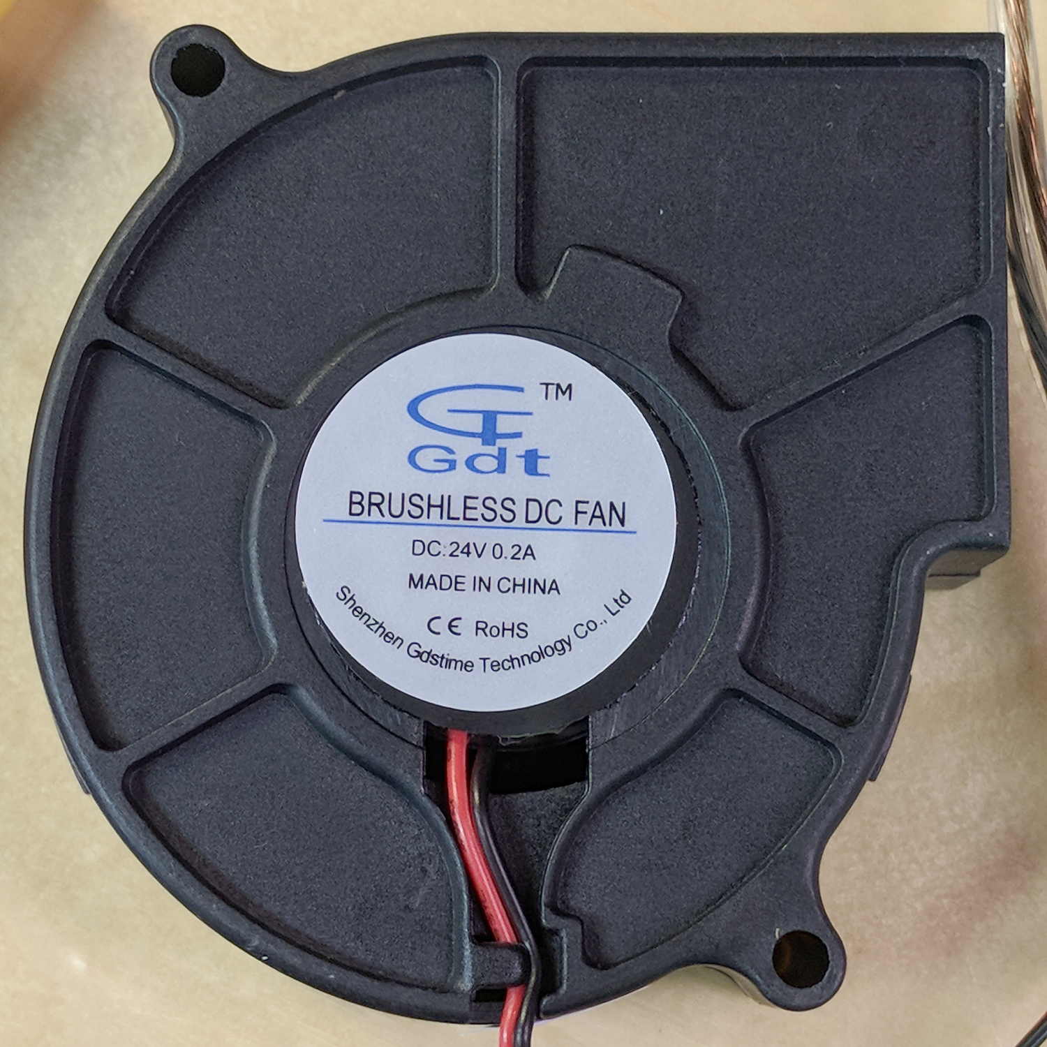
    The blower specs from the eBay listing:

    75MM 24V Brushless DC Blower Cooling Fan Exhaust Fan

    • Dimension:75(L)x75(W)x30(H)mm
    • Connector:2Pin-PH2.0
    • Rated Voltage: DC24V
    • Rated Current: 0.2±10% Amp
    • Rated Speed: 3800±10%rpm
    • Air flow:1.8CFM
    • Noise: 23±10%dBA
    • Bearing Type: Sleeve
    • Life: 35000 hours
    • Cable Lenght: 32cm(12.5in)
    • Weight: 75g/pcs

    The case is about 75 mm × 75 mm × 30 mm, so the generic part number seems to be 7530, with many variations. However, they all seem to resolve to the same blower with different models drawing different current at specific voltages (clicky for more dots, JPG blurriness in original):

    GDT7530S12B BLDC blower parameter table
    GDT7530S12B BLDC blower parameter table

    The blower in hand roughly corresponds to the bottom line of the 24 V section:

    • 0.21 A
    • 4000 RPM
    • 16.3 CFM
    • 1.1 inch H2O pressure
    • 43 dBA

    There’s a gross discrepancy between the eBay 1.8 CFM and the chart 16.3 CFM, but the other parameters seem within handwaving distance and, yo, it’s from eBay. ‘Nuff said.

    The graph up top shows the results with an unrestricted output opening.

    For more realistic results with some resistance to air flow, I taped a small anemometer to the blower output:
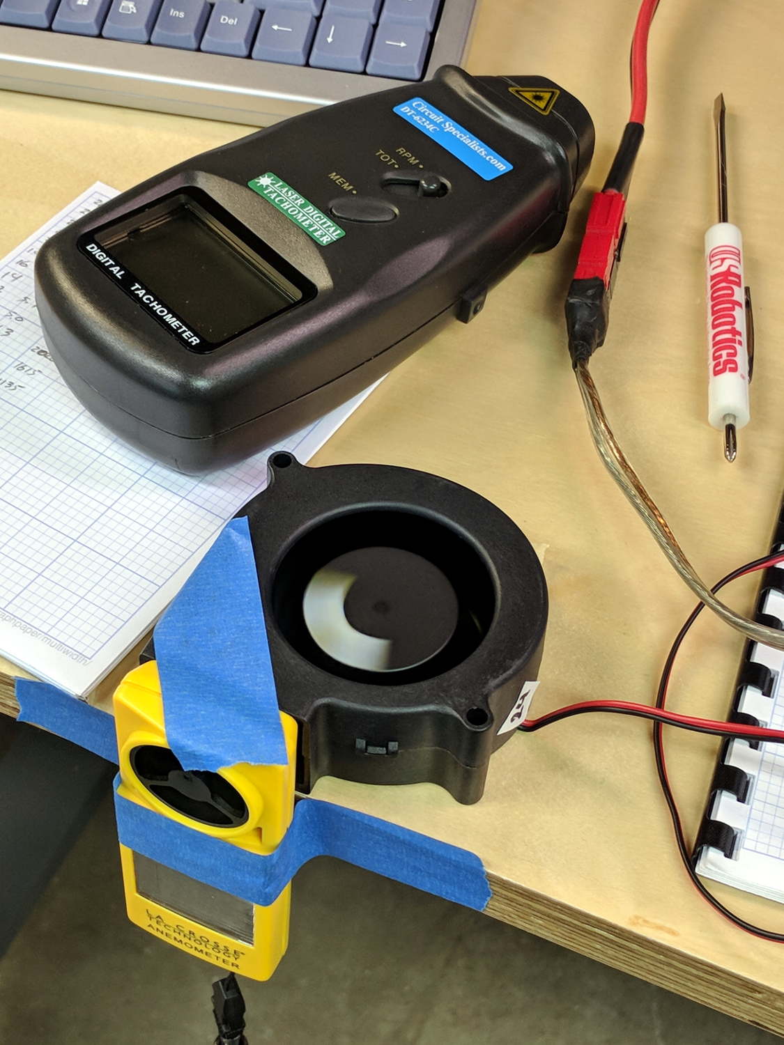
    Blower air flow test
    Blower air flow test

    Which produced:

    BLDC Blower - RPM Flow vs V - anemometer
    BLDC Blower – RPM Flow vs V – anemometer

    In very round numbers, the anemometer aperture is 400 mm², so the 9 m/s air flow at 24 V works out to 3.6×10⁻³ m3/s = 0.13 CFS = 7.6 CFM. Which is maybe half the 16.3 CFM spec, but they’re surely using a fancier anemometer with much lower back pressure. Close enough, anyway. Fer shure, 1.8 CFM is wrong.

    Completely blocking the inlet with a plastic sheet to simulate the blower pulling air from, e.g., a vacuum table:

    BLDC Blower - RPM vs V - blocked inlet
    BLDC Blower – RPM vs V – blocked inlet

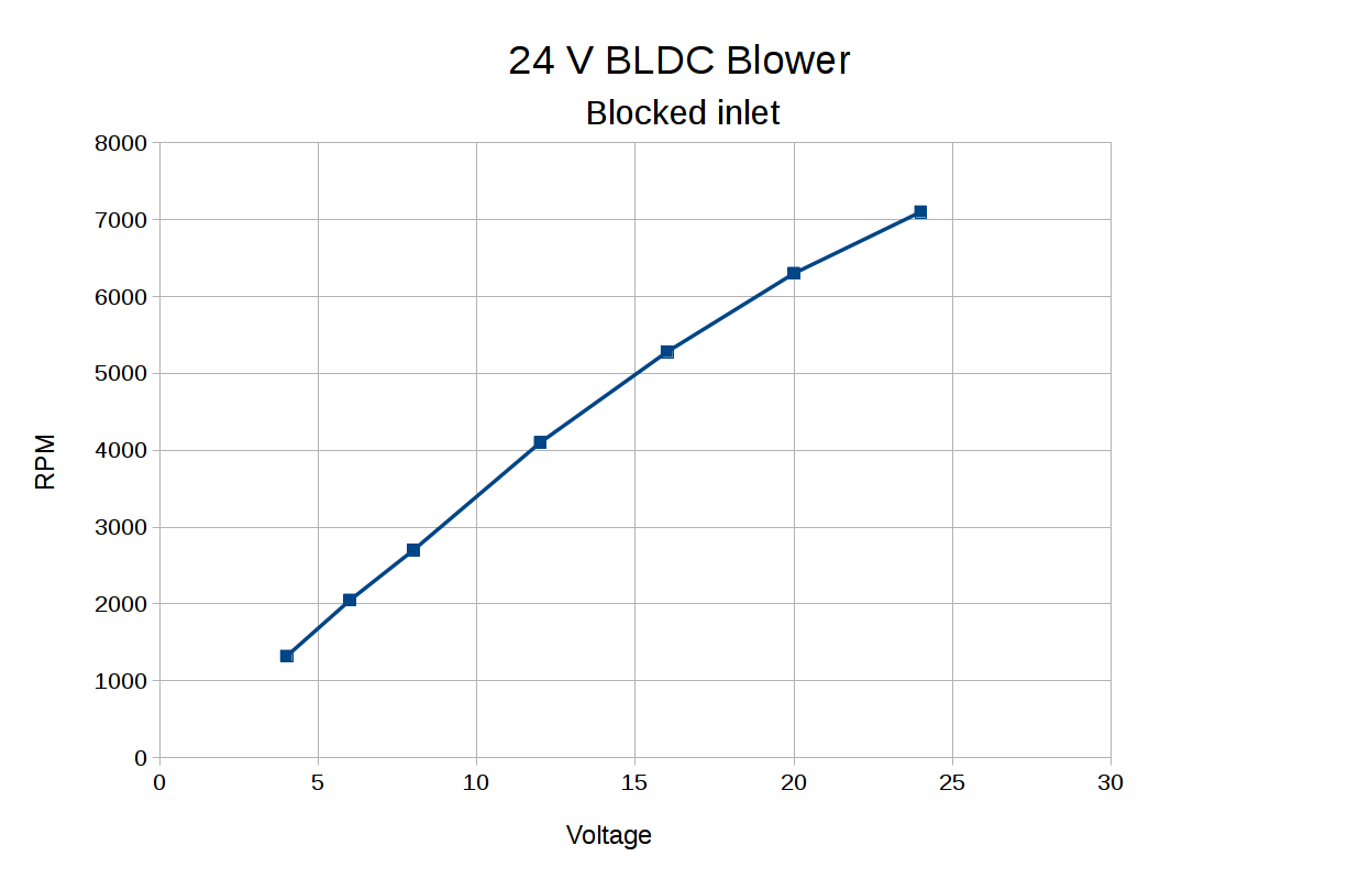
    The RPM varies more linearly with voltage when the blower isn’t accelerating any air.

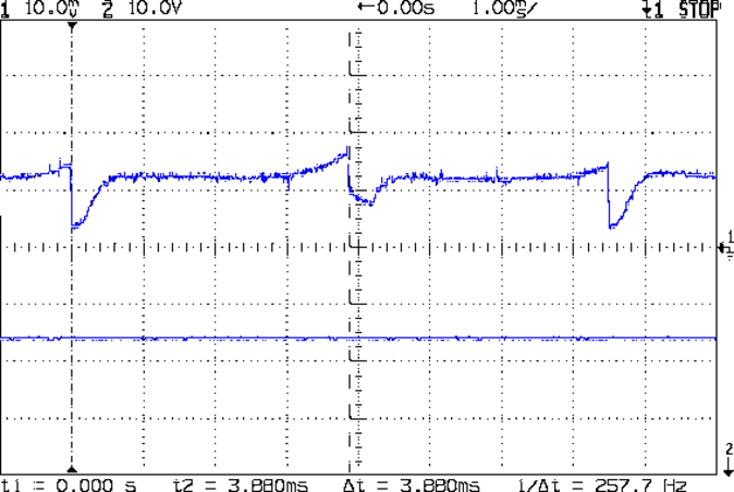
    Some current waveform show why you really shouldn’t run fans in series to “split the power supply”, as seems common in 3D printers with 24 VDC power supplies.

    From a 24 V supply, the current drops to 50 mA every 75 ms (200 mA/div):

    BLDC 24V Blower - 24 V - 200mA-div
    BLDC 24V Blower – 24 V – 200mA-div

    From a 12 V supply, even weirder things happen (50 mA/div):

    BLDC 24V Blower - 12 V - 50mA-div
    BLDC 24V Blower – 12 V – 50mA-div

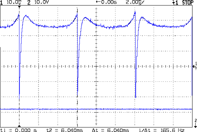
    Note that you can’t reduce the fan’s supply voltage by applying PWM to the current, as happens in essentially all 3D printers for “speed control”. Basically, PWM turns the fan off several hundred times every second, which does not modulate the voltage.

    I have no way to measure pressure, but if the 1.1 inch H2O number comes close to reality, the blower can produce 1.5 lb of clamping force per square foot. Which isn’t a lot, granted, but it might suffice for paper and vinyl cutting.

    The DRV10866 BLDC fan controller doc from TI is completely unrelated to the blower in question, but gives a reasonable introduction to the subject.

  • Streaming Radio Player: RPi and OLED Updates

    Because the OLED driver came from the pip package manager, not the Raspberry Pi’s system-level apt package manager, it (or they, there’s plenty of code under the hood) don’t get updated whenever I do system maintenance. The doc says this should do the trick:

    sudo -H pip install --upgrade luma.oled
    

    However, it turns out the new version has a slightly longer list of pre-requisite packages, causing the update to go toes-up at a missing package:

    Could not import setuptools which is required to install from a source distribution.
    Please install setuptools.
    

    So update (or install, for the new ones) the missing pieces:

    sudo apt-get install python-dev python-pip libfreetype6-dev libjpeg-dev build-essential
    

    Doing so produced a backwards-compatibility error in my Python code:

    ... change ...
    from luma.core.serial import spi
    ... into ...
    from luma.core.interface.serial import spi
    

    The motivation for all this fuffing and fawing came from watching some OLEDs wake up completely blank or become garbled in one way or another. Evidently, my slower-speed SPI tweak didn’t quite solve the problem, although it did reduce the frequency of failures. I have decided, as a matter of principle, to not embrace the garble.

    Soooo, let’s see how shaking all the dice affects the situation.

    It’s entirely possible the OLED controllers don’t quite meet their specs, of course, or have begun deteriorating for all the usual reasons.

  • MPCNC: Button Box Wiring

    The wiring hairball between the control button pendant and the Protoneer board looks like this:

    GRBL - Control button wiring
    GRBL – Control button wiring

    The as-built schematic, such as it is:

    GRBL Control button wiring - sketch
    GRBL Control button wiring – sketch

    Yes, the SSR negative output goes to the Protoneer + Power Input.

    I should drive the SSR from the Motor Enable output (in the external motor control header), rather than +5 V, to let GRBL control the motors, with a manual E-Stop override. The A4988 drivers require -Enable, so:

    • -Enable to SSR -Control input (replaces GND)
    • +5 V to BRS to SSR +Control input (as before)

    The SSR Control input draws 13 mA at 5 V, suggesting I should drive the AC SSR (for the spindle motor) from the DC SSR output, rather than paralleling the two on a single Arduino output pin.

    I belatedly recognized the E-Stop BRS as an instantiation of an SCP-001-J Keter-class anomaly; it is now appropriately labeled:

    MPCNC EStop as SCP-001-J
    MPCNC EStop as SCP-001-J

    I can attest to its effect on rational thought; a molly-guard may be required.

  • J5-V2 Flashlight: Front End Rattle

    After a year of fairly light use, the lens holder (and “attack ring”) of my J5-V2 flashlight worked loose and began to rattle. The ring holding the lens in place turned out to be finger-loose, but that wasn’t the entire problem, so I removed it and looked inside:

    J5-V2 Flashlight - LED view
    J5-V2 Flashlight – LED view

    The mysterious alien egg resides on the upper-right side of the LED emitter.

    The aluminum ring holding the LED assembly in place was also finger-loose, so I unwound it to take the whole front end apart:

    J5-V2 Flashlight - front parts
    J5-V2 Flashlight – front parts

    Reassembly with a few dabs of Loctite in appropriate places should prevent future rattles.

    Given the number of … issues … accompanying this thing, I’d say it’s not been a good cost performer. The Anker LC40 and LC90 flashlights work much better.


  • MPCNC: Autolevel Probe, Tactile Switch Edition

    So I intended to shrink the Autolevel probe with 1/8 inch drill rod and a tactile membrane switch:

    MPCNC - Simple Z probe - pogo tactile switch
    MPCNC – Simple Z probe – pogo tactile switch

    Unfortunately, it didn’t work nearly as well as I expected, because the switch membrane requires slightly less than the 180 g of pressure that pushes the P100 pogo pin entirely into its housing, leaving no overtravel worth mentioning. The membrane switch mechanism itself has much less than 1 mm of overtravel after the dome snaps, which left me with an uncomfortable feeling of impending doom.

    I managed to figure that out before completely assembling the thing, saving me a bit of time.

    The end of the pogo pin initially sported a dot of epoxy to spread the load over the switch dome:

    Pogo pin with epoxy switch-pusher drop
    Pogo pin with epoxy switch-pusher drop

    I dismantled the pogo pin to see whether I could substitute a more forceful spring how it worked. As expected, a teeny spring drives the probe up against a trio of indentations in the brass housing. I didn’t expect the probe to have such an intricate shape, but it’s obvious in retrospect.

    The OpenSCAD code for the housing required minimal tweakage from the larger version, so it’s not worth immortalizing.

  • USB Camera Re-Cabling

    The bCNC doc shows how to use a USB camera for XY alignment and I want to try it out. The Box o’ USB Cameras emitted a likely candidate with a focusing lens, six (!) white LEDs, and a ball mount attached to an aggressive spring clip, but its thick USB cable included a lumpy brightness pot for the LEDs and sprouted a mic plug (apparently, it predated cheap USB audio):

    USB Camera - OEM wiring
    USB Camera – OEM wiring

    The Box o’ USB Cables emitted a surprisingly long cable amputated from some random hunk of consumer electronics.

    The LED brightness won’t need much adjustment after the first few minutes. I found a little 2 kΩ trimpot to fit the PCB holes:

    USB Camera - inside - brightness pot
    USB Camera – inside – brightness pot

    Miracle of miracles, the dial ended up almost centered behind the original mic pore. A few minutes of gentle filing embiggened the pore and moved it over the trimpot:

    USB Camera - front with brightness pot
    USB Camera – front with brightness pot

    Yeah, the hole may need a plug or tape to keep the dust out, but there’s an even bigger gap around the lens.

    It produces a 640×480 picture with pretty much the expected quality, which should suffice for its intended purpose.

    Next step: stick it somewhere on the MPCNC.

  • Streaming Radio Player: OLED Garble

    Even in the dim light of dawn, it’s obvious slowing the SPI clock to 1 MHz didn’t quite solve the problem:

    RPi OLED display - garbled
    RPi OLED display – garbled

    The display started up fine, became encrypted during the next few hours, and remained garbled as the track information changed. This is almost certainly a bad SPI transfer trashing the OLED module’s control registers.

    Dropping the clock to the absolute minimum of 0.5 MHz didn’t help, either:

    serial = spi(device=0,port=0,bus_speed_hz=500000)
    device = sh1106(serial)
    

    This particular display woke up blank after loading the new code, then worked OK after another reset. The other streamers lit up as expected on the first try, so the slower SPI isn’t making the situation instantly worse.

    Running the clock at 1 MHz definitely reduced the failure rate, which suggests it’s a glitchy thing.

    Good embedded systems practice suggests resetting the entire display from scratch every now and again, but my streamer code has no concept of elapsed time. Opening that particular can o’ worms would almost certainly result in an on-screen clock and I do not want to go there.

    I suppose I must get a new oscilloscope with SPI bus decoding to verify all the SPI setup and hold times …