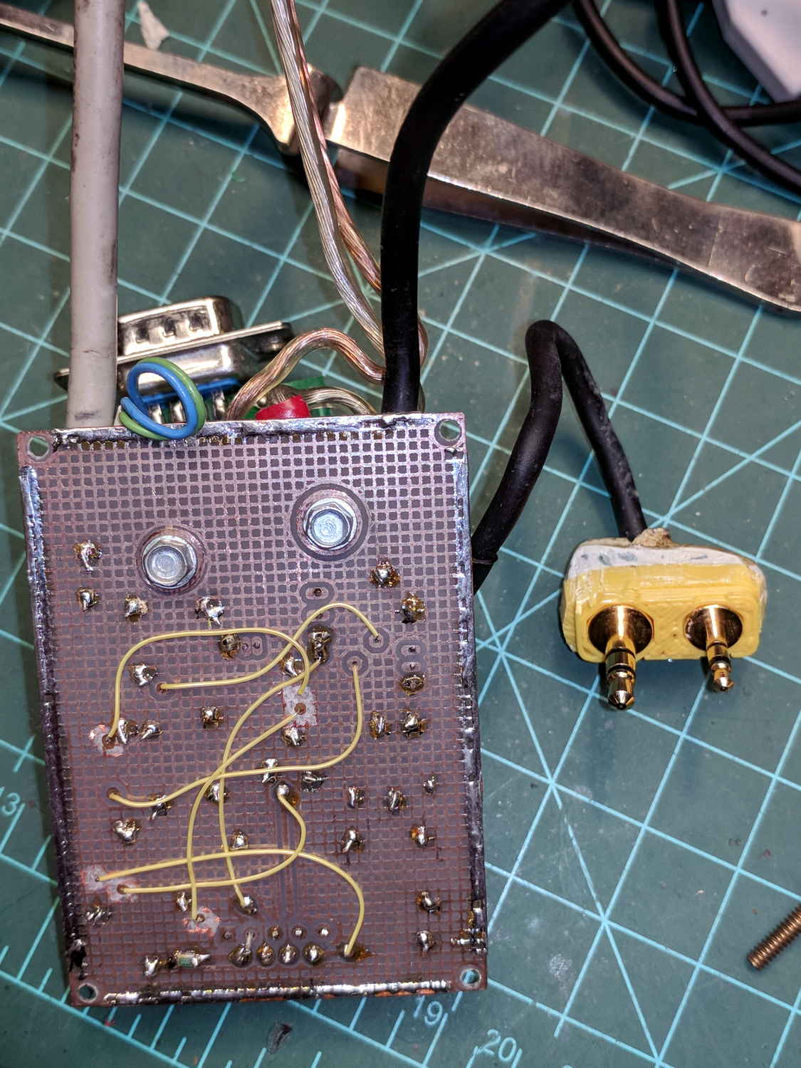
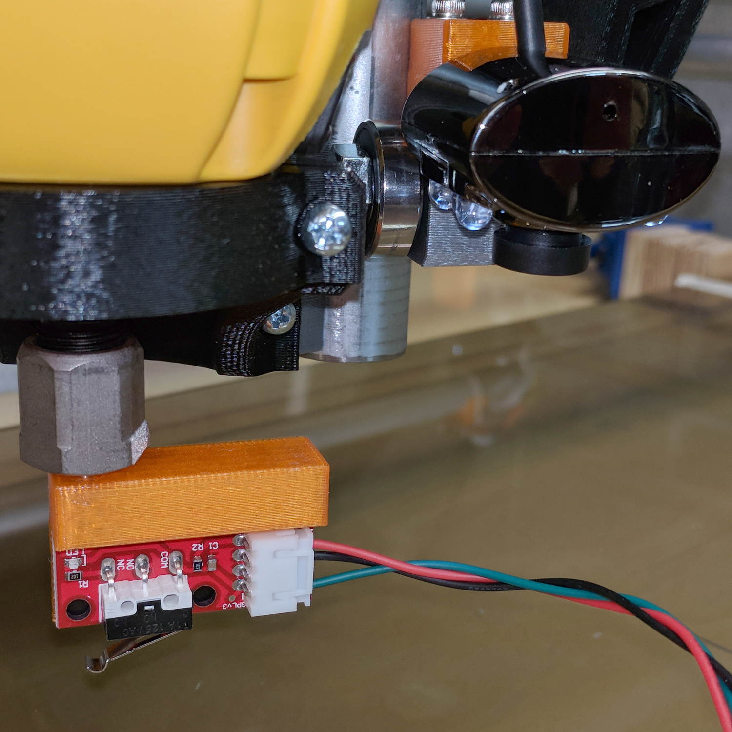
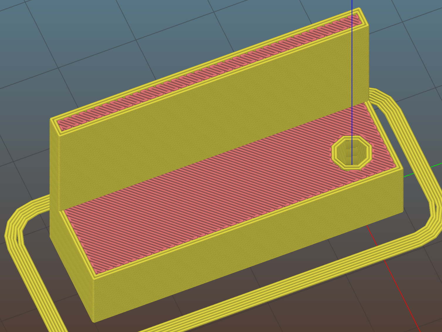
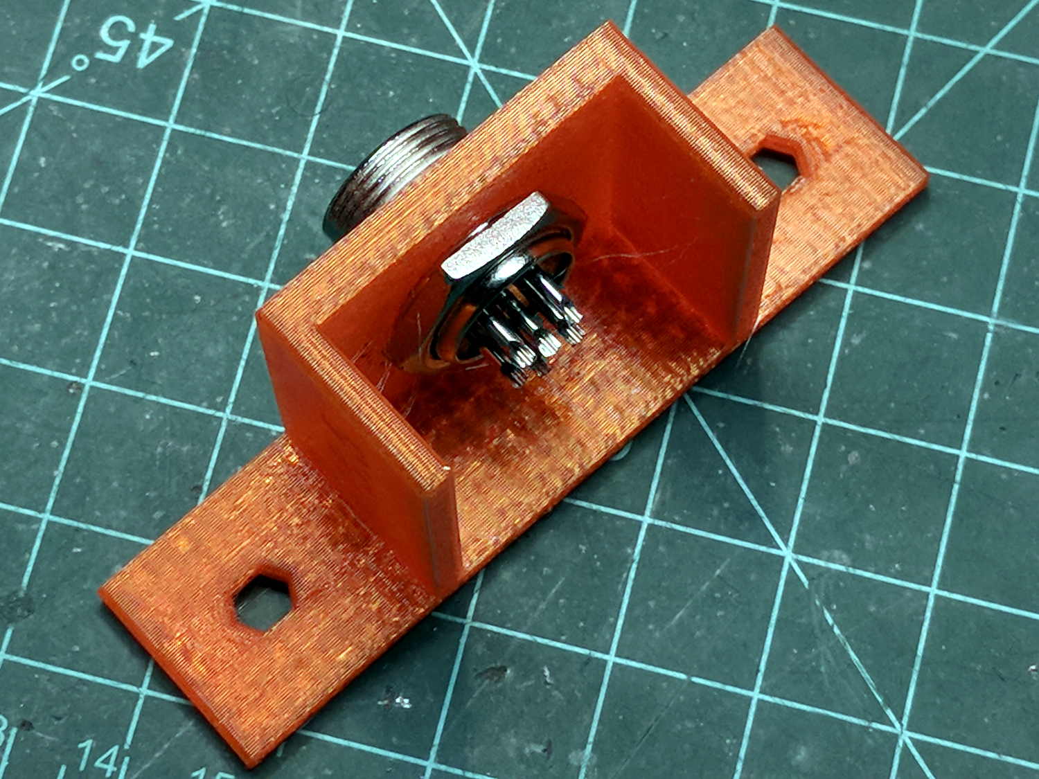
This will eventually end up on a board supporting the GRBL controller box:

It’s a direct cut-n-paste descendant of the old NEMA motor mount.
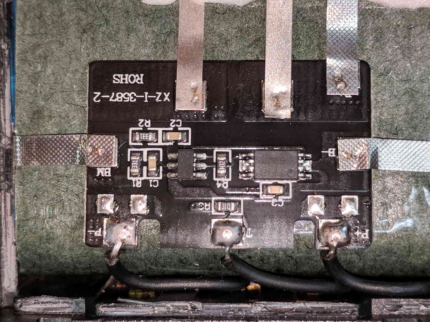
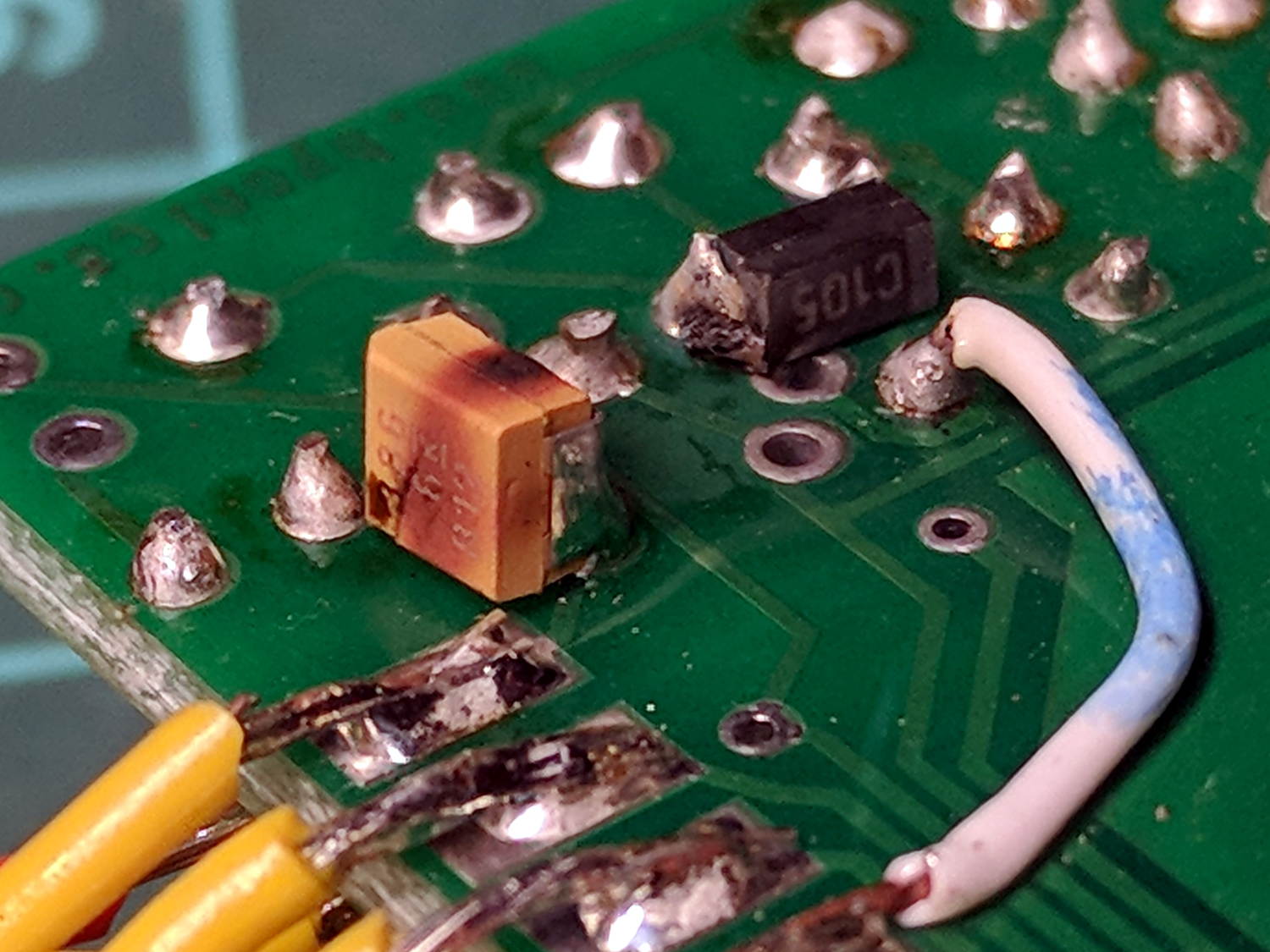
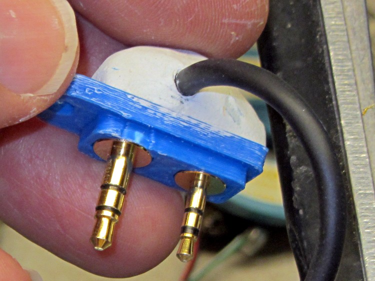
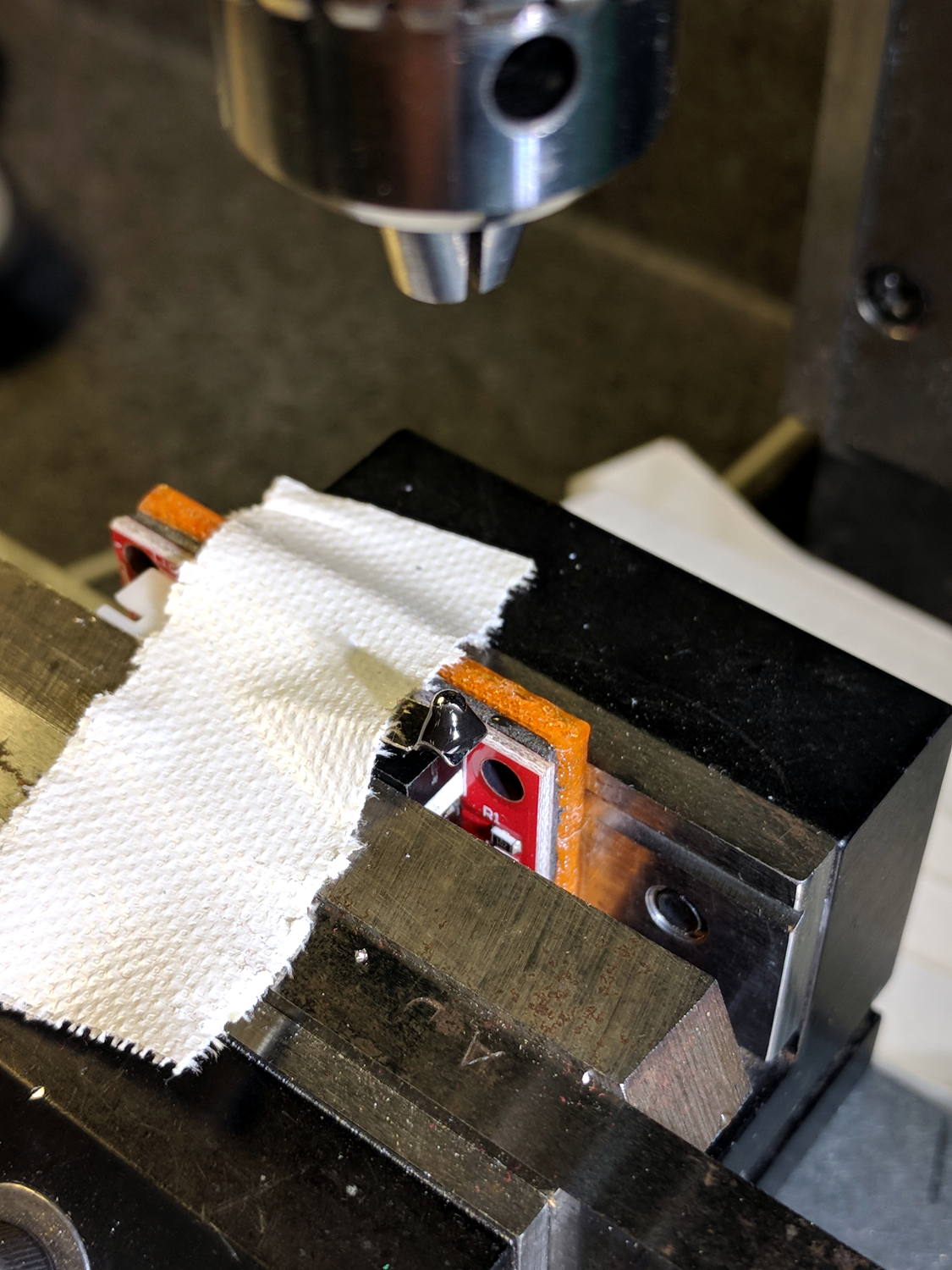
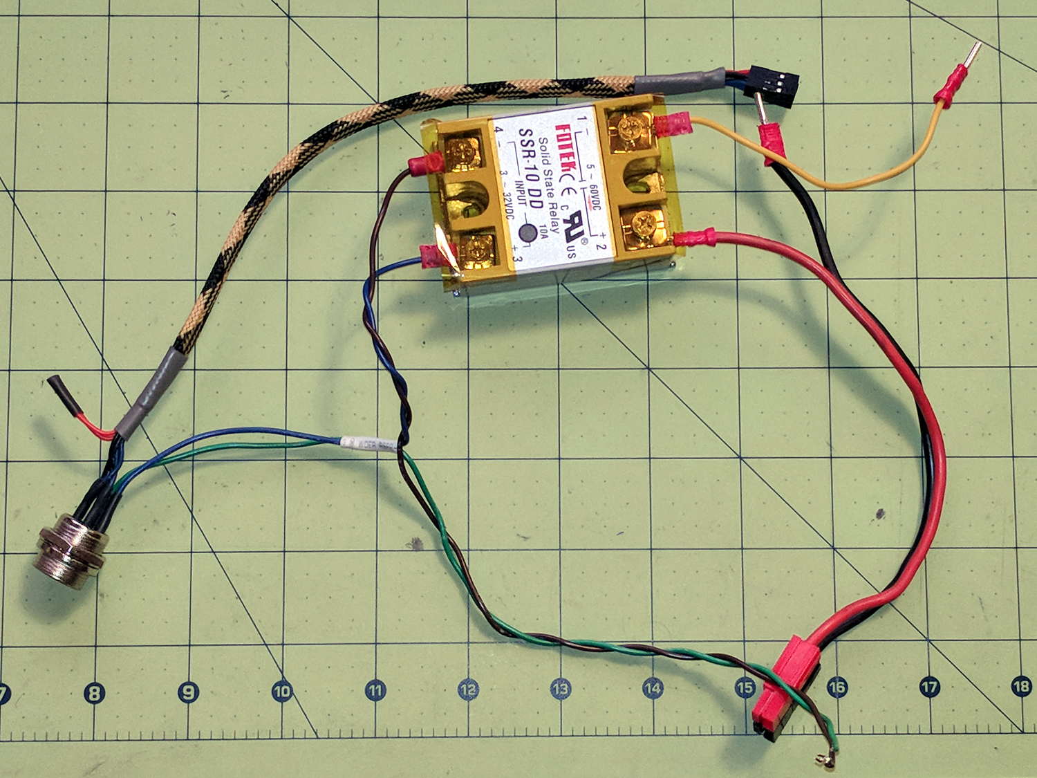
The nut threads onto the connector behind the bulkhead, so you must either wire it in place or make very sure you can feed all the terminations through the hole:
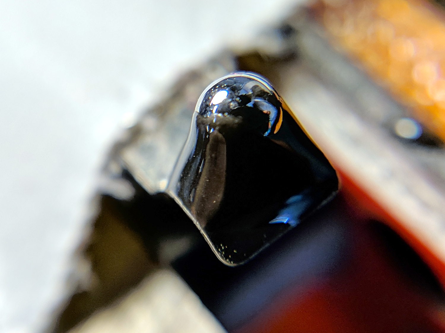
Given the previous hairball, I think in-situ soldering has a lot to recommend it:
The OpenSCAD source code as a GitHub Gist:
This file contains hidden or bidirectional Unicode text that may be interpreted or compiled differently than what appears below. To review, open the file in an editor that reveals hidden Unicode characters.
Learn more about bidirectional Unicode characters
| // Circular connector bracket | |
| // Ed Nisley KE4ZNU 2018-02-22 | |
| //– Extrusion parameters | |
| ThreadThick = 0.25; | |
| ThreadWidth = 0.4; | |
| HoleWindage = 0.3; // enlarge hole dia by this amount | |
| function IntegerMultiple(Size,Unit) = Unit * ceil(Size / Unit); | |
| Protrusion = 0.1; // make holes look good and joints intersect properly | |
| //– Useful sizes | |
| inch = 25.4; | |
| Tap10_32 = 0.159 * inch; | |
| Clear10_32 = 0.190 * inch; | |
| Head10_32 = 0.373 * inch; | |
| Head10_32Thick = 0.110 * inch; | |
| Nut10_32Dia = 0.433 * inch; | |
| Nut10_32Thick = 0.130 * inch; | |
| ID = 0; | |
| OD = 1; | |
| LENGTH = 2; | |
| //– Mount Sizes | |
| Connector = [14.6,15.5,4.0]; // connector thread; ID = dia at flat | |
| Screw = [5.1,10.0,3.0]; // screw size, more-or-less 10-32, OD & LENGTH for head | |
| MountWidth = IntegerMultiple(2*Connector[OD],ThreadWidth); // use BCD for motor clearance | |
| MountThick = IntegerMultiple(Connector[LENGTH],ThreadThick); // for stiffness | |
| WallThick = 3.0; // default wall thickness | |
| StandThick = IntegerMultiple(WallThick,ThreadWidth); // baseplate | |
| StrutThick = IntegerMultiple(WallThick,ThreadWidth); // sides holding motor mount | |
| UprightLength = MountWidth + 2*StrutThick; | |
| StandBoltHead = IntegerMultiple(Head10_32,5); // bolt head rounded up | |
| StandBoltOC = IntegerMultiple(UprightLength + 2*StandBoltHead,5); | |
| StandLength = StandBoltOC + 2*StandBoltHead; | |
| StandWidth = 2*StandBoltHead; | |
| StandBoltClear = (StandLength – UprightLength)/2; // flat around bolt head | |
| Recess = StandWidth – MountThick; | |
| echo(str("Stand Base: ",StandLength," x ",StandWidth," x ",StandThick)); | |
| echo(str("Stand Bolt OC: ",StandBoltOC)); | |
| echo(str("Strut Thick: ",StrutThick)); | |
| //———————- | |
| // Useful routines | |
| module PolyCyl(Dia,Height,ForceSides=0) { // based on nophead's polyholes | |
| Sides = (ForceSides != 0) ? ForceSides : (ceil(Dia) + 2); | |
| FixDia = Dia / cos(180/Sides); | |
| cylinder(r=(FixDia + HoleWindage)/2, | |
| h=Height, | |
| $fn=Sides); | |
| } | |
| //———————- | |
| // Model | |
| module MotorMount() { | |
| difference() { | |
| translate([StandThick/2,0,StandWidth/2]) | |
| cube([(MountWidth + StandThick),StandLength,StandWidth],center=true); | |
| translate([-Protrusion/2,0,StandWidth – (Recess – Protrusion)/2]) | |
| cube([(MountWidth + Protrusion),MountWidth,(Recess + Protrusion)],center=true); | |
| translate([0,0,-Protrusion]) | |
| PolyCyl(Connector[OD],StandWidth,4*4); | |
| for (j=[-1,1]) // cutouts over bolts | |
| translate([-Protrusion/2, | |
| j*((StandLength – StandBoltClear)/2 + Protrusion/2), | |
| StandWidth/2]) | |
| cube([(MountWidth + Protrusion), | |
| (StandBoltClear + Protrusion), | |
| (StandWidth + 2*Protrusion)],center=true); | |
| for (j=[-1,1]) // stand bolt holes | |
| translate([(MountWidth/2 – Protrusion),j*StandBoltOC/2,StandWidth/2]) | |
| rotate([0,90,0]) | |
| rotate(180/6) | |
| PolyCyl(Clear10_32,StandThick + 2*Protrusion,6); | |
| translate([0,-(UprightLength/2 – ThreadWidth/2),StandWidth/2]) | |
| rotate([90,180,0]) | |
| linear_extrude(ThreadWidth,convexity=10) | |
| text(text=str(Connector[OD]),size=6,spacing=1.20,font="Arial",halign="center",valign="center"); | |
| } | |
| } | |
| //———————- | |
| // Build it | |
| MotorMount(); | |