Ed Nisley's Blog: Shop notes, electronics, firmware, machinery, 3D printing, laser cuttery, and curiosities. Contents: 100% human thinking, 0% AI slop.
Some ex post facto notes from the first SquidWrench Electronics Workshop, in the expectation we’ll run the series from the start in a while. I should have taken pictures of my scribbles on the whiteboard.
Define:
Voltage – symbol E (Electromotive Force or some French phrase), unit V = volt
Current – symbol I (French “intensity” or some such), unit A = ampere
Resistance – symbol R (“resistance”), unit Ω (capital Greek Omega) = ohm
Introduce Ohm’s Law & permutations, postpone calculations.
Measure the actual voltage of assorted cells & batteries. Identify chemistry, internal wiring:
1.2 = nickel-cadmium or nickel-metal-hydride
1.5 = carbon-zinc or alkaline
2 V = lead-acid
3.0 = primary lithium
3.6 – 3.7 = rechargeable lithium, several variations
4.8 = 4 x 1.2 V
7.2 = 6 x 1.2 V
7.4 = 2 x 3.6 V
9.6 = 8 x 1.2 V
10.8 = 3 x 3.6 V
12 = 6 x 2 V
Measure various resistors, favoring hulking finger-friendly sandstone blocks.
Introduce metric prefixes:
Engineering notation uses only multiple-of-three exponents
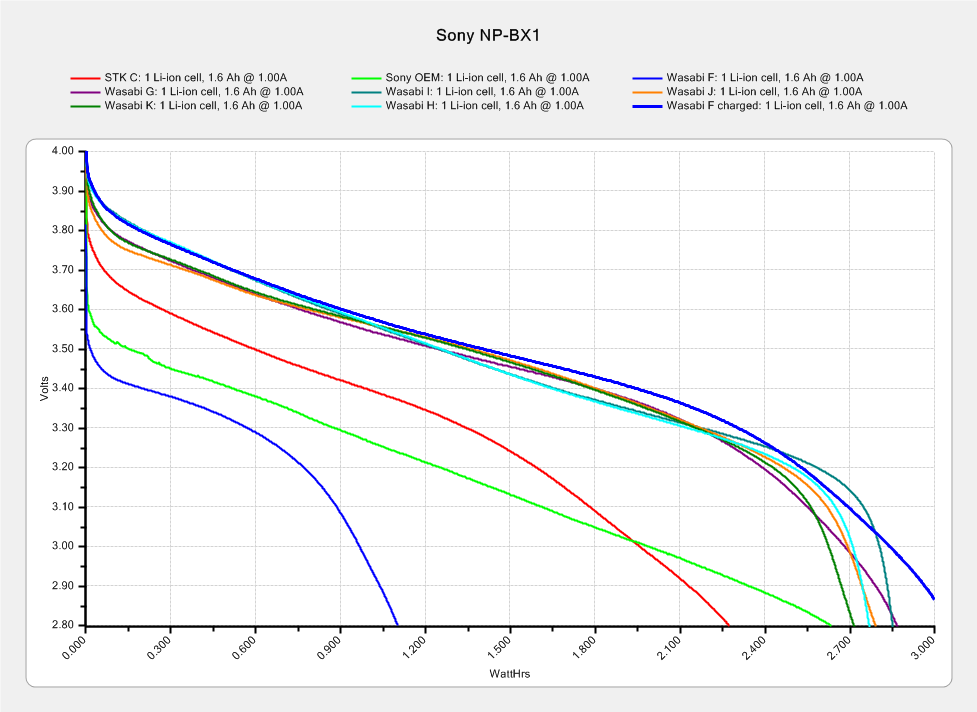
The genuine Sony NP-BX1 that came with the AS30V camera suffers from voltage depression (green trace) and no longer survives a typical ride:
Sony NP-BX1 – 2018-04-24
The STK C battery (red trace) is also pretty much kaput, so the two of them go into the recycle bag.
The very short blue trace is the Wasabi F battery after a ride, showing about 1 W·h remaining of the initial charge. After a full change, the upper blue trace shows it has a capacity in the same range as the others. Our rides are about an hour long, so the camera draws somewhat less than the 1 A test current, roughly what I’d estimated from other data.
This file contains hidden or bidirectional Unicode text that may be interpreted or compiled differently than what appears below. To review, open the file in an editor that reveals hidden Unicode characters.
Learn more about bidirectional Unicode characters
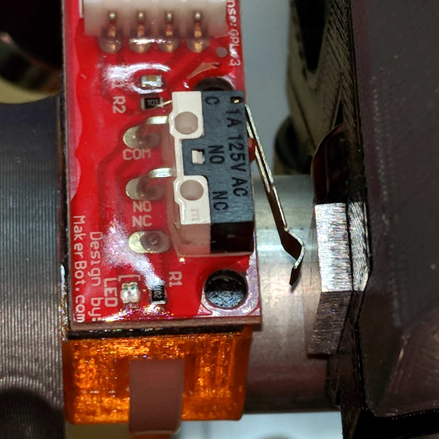
The overall XY travel is slightly smaller than the initial configuration, because the router sticks out further than the penholder I’d been using. Increasing the $27 Homing Pulloff distance to 3 mm leaves a comfortable space beyond the limit switches after homing to the positive end:
MPCNC – X-axis endstop – home
Adjusting the $13[01] XY travel distances and switch positions on the other end of the rail leaves a similar comfort zone at the negative end:
MPCNC – X-axis endstop – X min
Both switches now live on the rear X-axis rail and appear as seen from behind the bench; they just look backwards. The Y-axis switches are on the left rail and look exactly the same.
The XY travel works out to 630 × 460 mm = 24.8 × 18.1 inch, which is Good Enough.
Some fiddling with the Z axis limit switch tape mask produces a nice round 100 mm = 3.9 inch vertical travel. The Z-axis rails just barely clear the table at the lower limit and just barely stay in the bottom bearings at the upper limit, so it’s a near thing. In practical terms, the rails or the tool will smash into the workpiece sitting atop the table before the limit switch trips.
Setting both $20=1 Soft Limits and $21=1 Hard Limits may be excessive, but I vastly prefer having the firmware detect out-of-range moves and the hardware forcibly shut down if the firmware loses track of its position, rather than letting it grind away until I can slap the BRS. The steppers aren’t powerful enough to damage anything, of course, so it’s a matter of principle.
The $N1=G10L2P1X-633Y-463Z-3 sets the default G54 coordinate origin to the front-left corner, with Z=0 at the home position up top, so as to prevent surprises. I expect to use G55 for most work holder touchoffs, although we’ll see how that plays out.
The G28 and G30 settings depend on the tool change location and the Z-axis probe location, so they’re still not cast in concrete.
Anybody capable of fogging a mirror knows how this scam works:
TCU 100 – Giveaway teaser
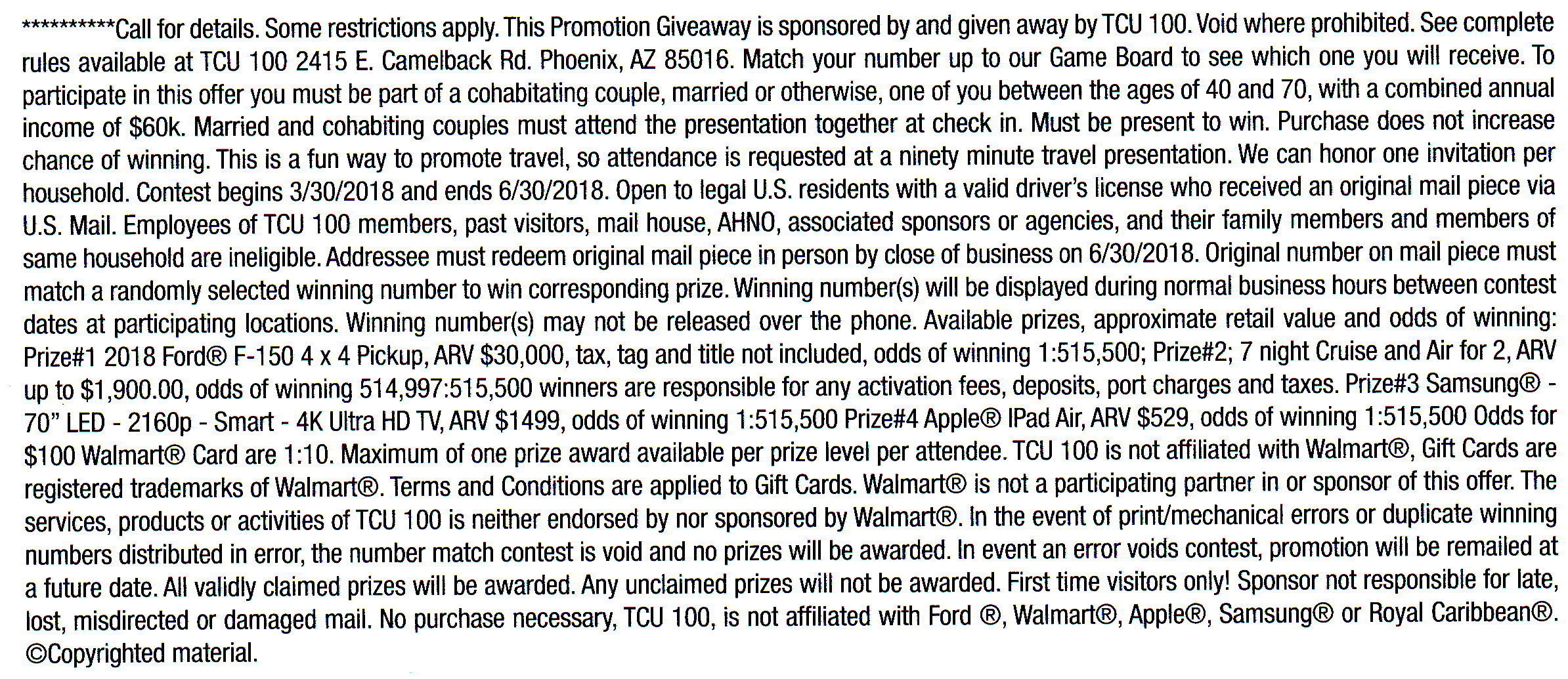
The copious fine print says you can only see the actual fine print by traveling to Arizona:
TCU 100 – Giveaway fine print
I’m nowhere near hungry enough to like the odds, even for a $100 Walmart gift card.
An Auto-V.I.N Gauge (their choice of punctuation) must improve the response rate:
TCU 100 – Auto-VIN Gauge – activated
Is it any surprise the numbers match?
TCU 100 – scratch-off number
No. No, it’s not.
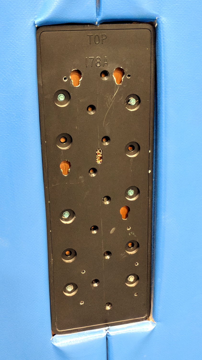
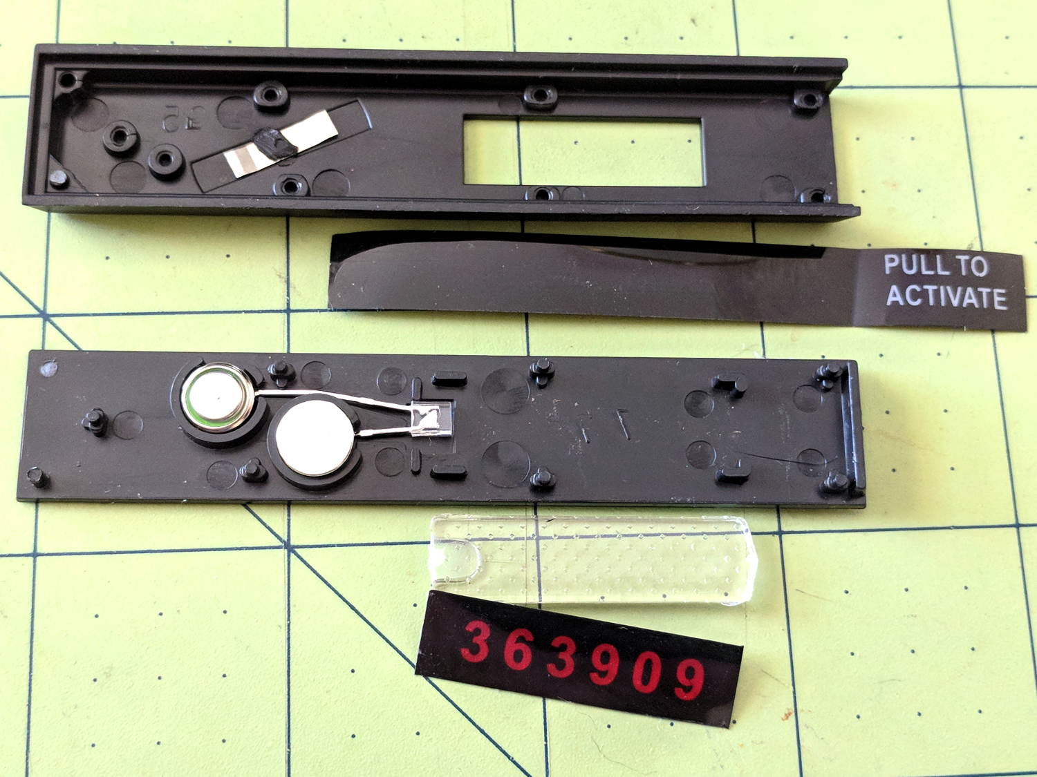
The “Gauge” actually contains parts, although fewer than IMO they want you to believe:
TCU 100 – Auto-VIN Gauge – components
It’ll serve to produce measurable current & voltage for an upcoming Squidwrench Electronics Workshop and, because it need not survive the experience, we will take considerable liberties with it.
The red dial scale has the Guide Numbers (aperture × feet) and the lower black dial scale gives the lens apertures. The manual doesn’t mention the black figures above the red Guide Numbers; they’re metric Guide Number (aperture × meters), which would have been obvious back in the day.
The tidy shell slides off when you release a latch in the back:
Zeiss Ikon Ikoblitz 4 – front – stowed
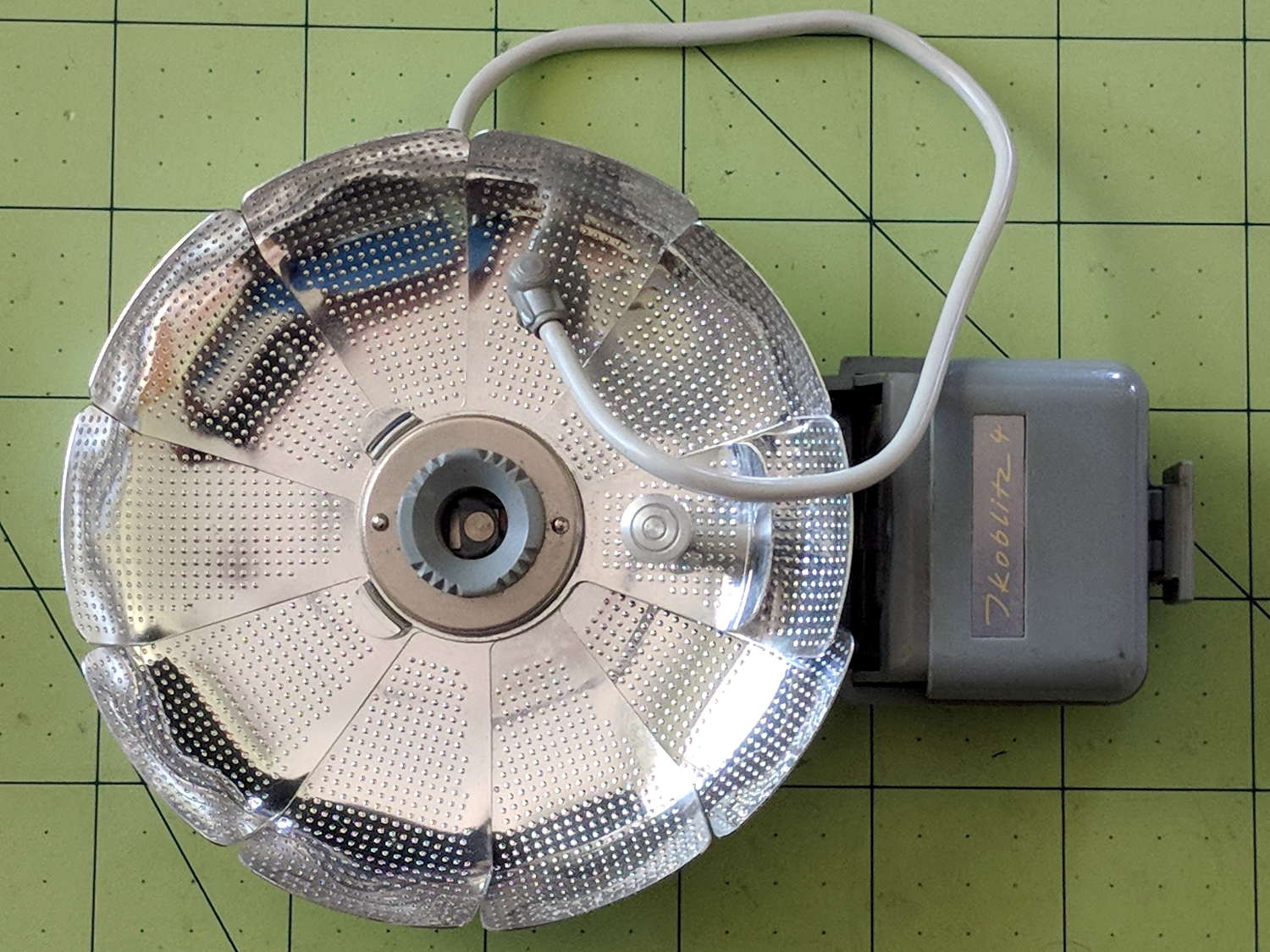
Then the reflector unfurls:
Zeiss Ikon Ikoblitz 4 – front unfurled
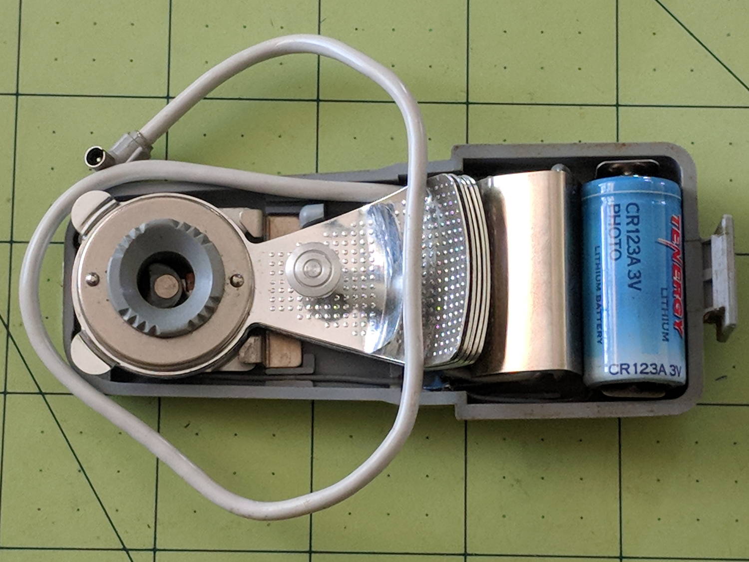
Mirabile dictu, the previous owner removed the 15 V “hearing aid” battery (Eveready 504, 60 mA·h in the 504A alkaline version) before storing the flash, leaving the contacts in pristine condition:
Zeiss Ikon Ikoblitz 4 – CR123A test fit
A 3 V CR123A primary lithium cell snaps perfectly into the battery holder, which I define as a Good Omen: a dab of circuitry could turn this into self-powered and highly attractive Art. This would be one of the very few applications well-suited for the coldest blue-white LEDs.
One could adapt an A23 12 V alkaline battery (33 mA·h) to the holder, at the cost of half the capacity.
The silver shield just to the left of the battery conceals a 250 μF (!) nonpolarized capacitor.
One could build a bayonet-base (GE #5 / Press 25) adapter or poke a doodad with a 9 mm cylindrical base into the M2 bulb adapter (unrelated to my M2 printer):