Ed Nisley's Blog: Shop notes, electronics, firmware, machinery, 3D printing, laser cuttery, and curiosities. Contents: 100% human thinking, 0% AI slop.
Back then, a 150 µF 450 V cap of the proper size (the 30 mm height being critical) was difficult to find and relatively expensive to purchase in onesies from the usual reliable sources, particularly as the repair advice I could find suggested it probably wasn’t the causing the monitor’s problems. So the monitor sat in pieces in an out-of-the-way corner of the Basement Laboratory while other events transpired.
As part of a long-delayed Great Cleanup of Small Projects, I discovered the caps are now four bucks delivered from halfway around the planet, so I got one, did the swap, reassembled the pieces, and the monitor works just like new. No pix, but you get the general idea.
For another few years, anyway.
For whatever reason, the 3.5 mm audio output seems dead. The monitor has a pair of teeny speakers that don’t do justice to its magnificent HDMI audio, but they’re entirely adequate for my simple needs: pre-SSH Raspberry Pi setup doesn’t call for much.
A recent Squidwrench meeting produced a treasure trove of discarded LED lighting, including a shoplight-style fixture in a narrow, finned aluminum extrusion. It was in “known-bad” condition, so I extracted the four LED panels, connected each one to a widowmaker cord, and determined I had two good ones, a mostly working one sporting some dead LEDs, and a corpse.
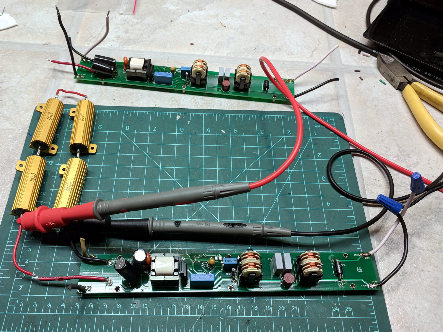
The working panels showed the power supplies produced about 19 V across two parallel strings of six LEDs, with each string running at 350 mA for a total of 700 mA = 13 W. I wired up a quartet of 6 Ω power resistors to check out the power supplies from the suspect panels:
LED Panel – power supply test setup
The supply in the background is truly dead. I can’t tell whether it killed the LEDs or the gaggle of failing LEDs dragged it down with them.
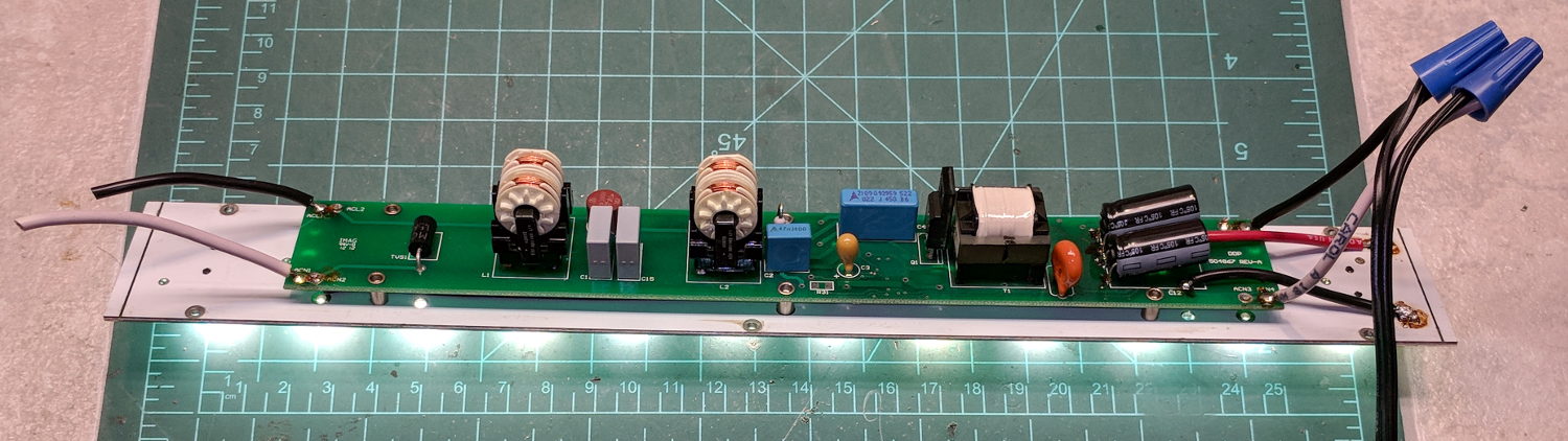
Some multimeter probing revealed enough live LEDs to restore the partially working panel. A rather sweaty interlude at the SqWr hot-air rework station transplanted the good LEDs, whereupon combining it with the live supply gave me a third fully functional panel:
LED Panel – restored
I did the test firing in the Basement Laboratory, because I’m nowhere near crazy enough to deploy a widowmaker line cord on the SqWr Operating Table in public.
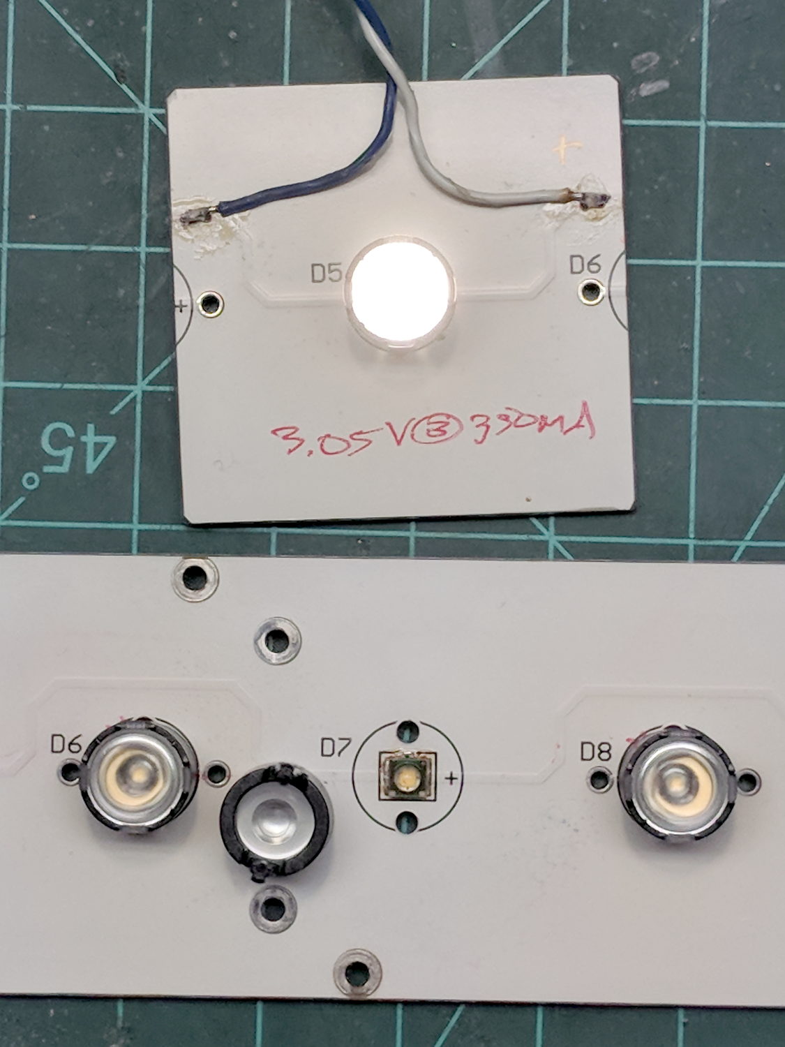
I bandsawed the last working LED from the gutted donor panel:
LED Panel – single LED test
The SMD LEDs mount on traces applied to and electrically insulated from the aluminum sheet, so unsoldering them required way more heat than you (well, I) might expect at first glance. A snap-on condenser lens over each LED concentrates the light into a nice cone, producing a narrow sheet of light from each panel.
The elaborate aluminum extrusion seems much too heavy for the individual panels, but those open-frame supplies definitely need more than casual protection. Now that LEDs are more common than when these panels came off the assembly line, I should probably replace the supplies with enclosed constant-current drivers and be done with it.
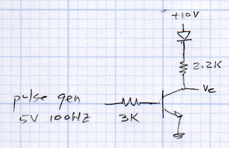
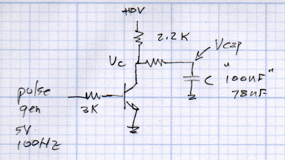
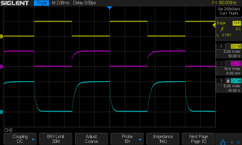
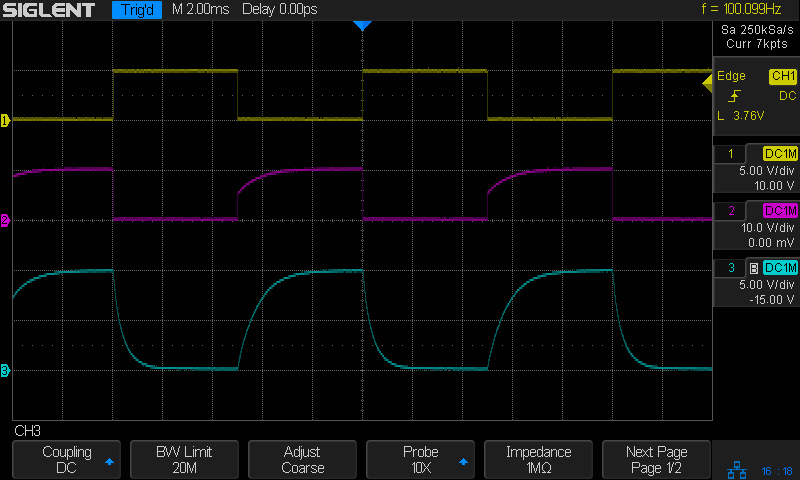
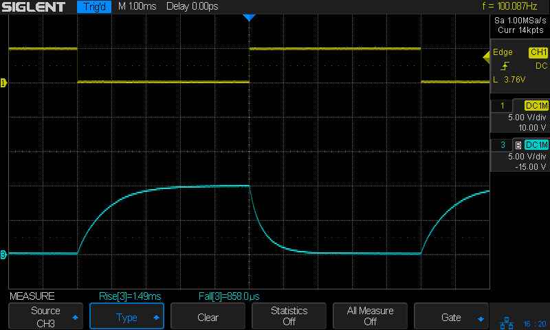
Having discussed transistors as current-controlled current sources, we can now select one as a victim use one as a switch, then add capacitors to learn about exponential charging, and introduce the oscilloscope as a vital tool.
NPN Switch – protoboard
So, we proceed:
Transistors as switches
Review graphical parameters
saturation voltage for high Ic
cutoff voltage for near-zero Ic
resistive load line: VR = Vcc – Vc
power dissipation hyperbola (at all Vc)
secondary breakdown limit (at higher Vc)
Something like this, only drawn much larger and with actual numbers:
Transistor characteristics – saturation and cutoff – load line
Reminder of linear vs. log scales converting hyperbolas into straight lines.
#from luma.core.interface.serial import spi
from luma.core.interface.serial import i2c

... snippage ...

# reduce SPI bus from default 8 MHz to (maybe) avoid OLED failure-to-start
#serial = spi(device=0,port=0,bus_speed_hz=1000000)

# use I2C bus to avoid SPI timing spec failure
serial = i2c(port=1,address=(0x78 >> 1))     # PCB label = 0x78, low bit = R/W
The OLED PCB lists the I2C address with the R/W bit
And then It Just Works, with one gotcha. Although the Python program shuts itself and the system down, the wall wart continues to supply power and, because the I2C bus doesn’t include a Reset line, the OLED display doesn’t know the RPi has gone away. So you must issue a command to turn it off before shutting down:
device.cleanup()        # ideally, switches to low-power mode
rc = subp.call(['sudo','shutdown','-P','now'])
Now, to discover what works … oddly … with these displays.
Dunno how I missed that while I had the cover off, but there it is. For future reference it’s C165, 47 µF 50 V, with an 8709 date code.
This being a PCB made back in the old days, likely with self-adhesive tape strips, the component pads inside ground and power pours lack thermal isolation decorations.
The solder joints on the bottom side looks better than these, honest:
Tek AM503 – replaced capacitor
The new cap is 56 µF 50 F, which seems Close Enough.
The other caps have reasonable ESRs, but I must lay in a stock of high-voltage ‘lytics, as the “new” one is definitely old enough to know better, too.
Now that I check, the amp still produces a very low amplitude 2 MHz sine wave on its 1 mA/div and 2 mA/div settings, suggesting Something Is Not Right™ in the front end, but it works well enough to let me defer that fix until later.
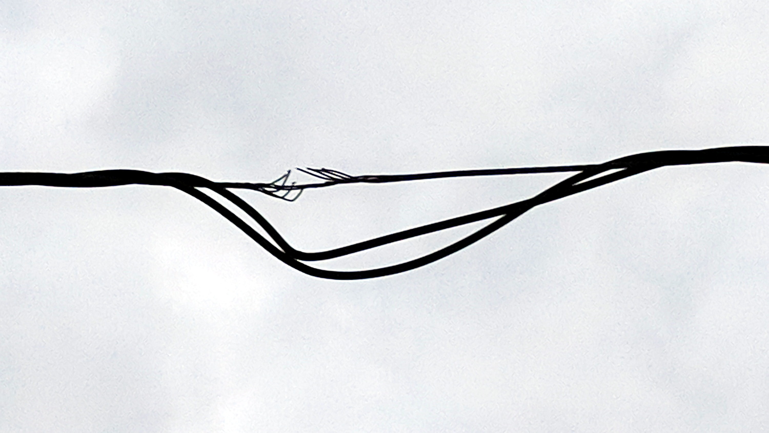
The neutral conductor is down to its last three strands:
Damaged neutral – over Redondo near pole 62859
Perhaps the power drop got snagged twice, because there’s a splice only a few feet away:
Damaged neutral and splice – over Redondo near pole 62859
Spotted overhead on Redondo near Rt 376 during an evening walk. I reported it using Central Hudson’s dead streetlight page, because there seems no other way to get their attention. It may be the homeowner’s responsibility, in which case a second splice will surely appear after the next power outage.
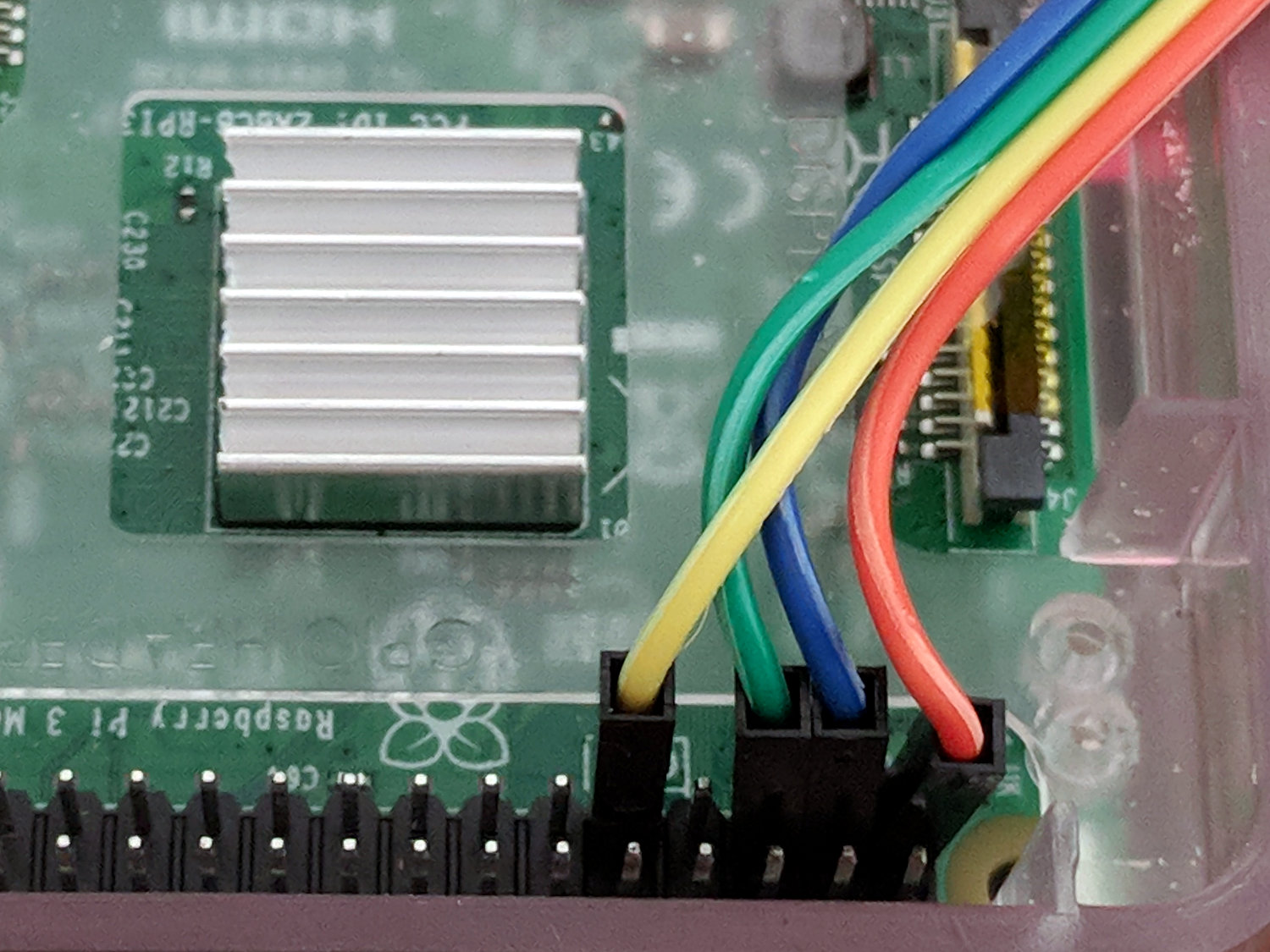
An Adafruit BNO055 connected to a Raspberry Pi 3 I2C bus, despite knowing it won’t work:
I2C 100kHz – BNO055 SCL 1 mA-div – B7 Rd error
The I2C bus ticks along at 100 kHz (nominal) = 62.5 kHz (actual), as described a while ago.
The three digital traces along the bottom are D0 = SCL, D1 = SDA, and D2 = trigger raised when the Python program detects an error.
The upper trace shows the SCL current (1 mA/div) between the Pi and the BNO055, as described yesterday, with the latter stretching the clock whenever the current goes negative.
The fourth burst is the BNO055 sending the chip’s temperature in response to a simple request:
I commend to your attention a useful tutorial on I2C bus protocols / transactions / signalling.
Over on the left, the BNO055 has SCL held low (-2 mA) during the ACK phase of the previous byte. The first upward SCL edge marks the ACK, with the BNO055 holding SDA low during the edge until the Pi drops SCL.
The BNO releases SDA when SCL goes low again, whereupon SDA goes high, exactly as it should.
Now, things gets ugly.
The -1 mA current on SCL shows both the Pi (+1 mA) and the BNO (-2 mA) are pulling SCL low. The BNO is clock-stretching after the ACK, which the Pi can’t handle.
The Pi seems to think the rising edge of SCL occurs when it stops pulling SCL down, at the point where the SCL current goes from -1 mA to -2 mA, halfway though the high SDA pulse. It reads SDA at that point and receives an incorrect binary 1 bit from SDA, because the BNO hasn’t yet seen a rising SCL edge.
The SCL rising edge occurs when the BNO055 releases SCL and produces the SCL sliver.
The two vertical cursors bracketing the sliver mark the 16 µs SCL timing produced by the Pi’s SCL clock, which is not the 10 µs you’d expect at 100 kHz.
The right cursor sits on the next rising edge, so the left cursor marks where SCL should rise: exactly where the Pi releases its hold on SCL and expects it to pop up.
That error happens about 6% of the time, producing a chip temperature 128 °C higher than reality. The other 94% of the reads either work correctly or, perhaps, encounter a bogus SDA state coincidentally delivering a binary zero that looks good.
Here’s a sample of a “good” read:
I2C 100kHz – BNO055 SCL 1 mA-div – B7 Rd OK – long SCL high
The stop bit is now off to the right, so the last rising SCL edge is the ACK. Counting leftward eight edges from the ACK, the left cursor marks where the SCL edge should be for bit B7. Instead it occurs instantly after the BNO releases its hold on SCL, shown by the transition from -2 mA to 0 mA. I don’t know the setup and hold times for the Pi’s I2C port, but 250-ish ns seem aggressive; I think the data transitions should happen close to the down-going SCL edges.
Running the I2C bus at 200 kHz seems to work fine, but it still has the same aggressive SDA-to-SCL setup time. Here’s a close look at the same situation as in the previous photo, with SCL set for 200 kHz:
This being a read, the BNO sets SDA to whatever it should be, then releases its clock-stretching hold on SCL about 200 ns later. The Pi raises SCL shortly thereafter and it apparently Just Works. Maybe it’s Good Enough to be consistent, but I’d like to run more tests before trusting it.
Anyhow, that’s how the Pi’s I2C hardware doesn’t handle a chip using clock stretching.