Ed Nisley's Blog: Shop notes, electronics, firmware, machinery, 3D printing, laser cuttery, and curiosities. Contents: 100% human thinking, 0% AI slop.
Not much to my surprise, my hack-job thermistor rebuild went bad:
M2 – thermistor – assembly 2
Having nothing to lose, I heated the brass tube over a butane flame to wreck the epoxy, which blew out with a satisfactory bang and filled the Basement Laboratory with The Big Stink.
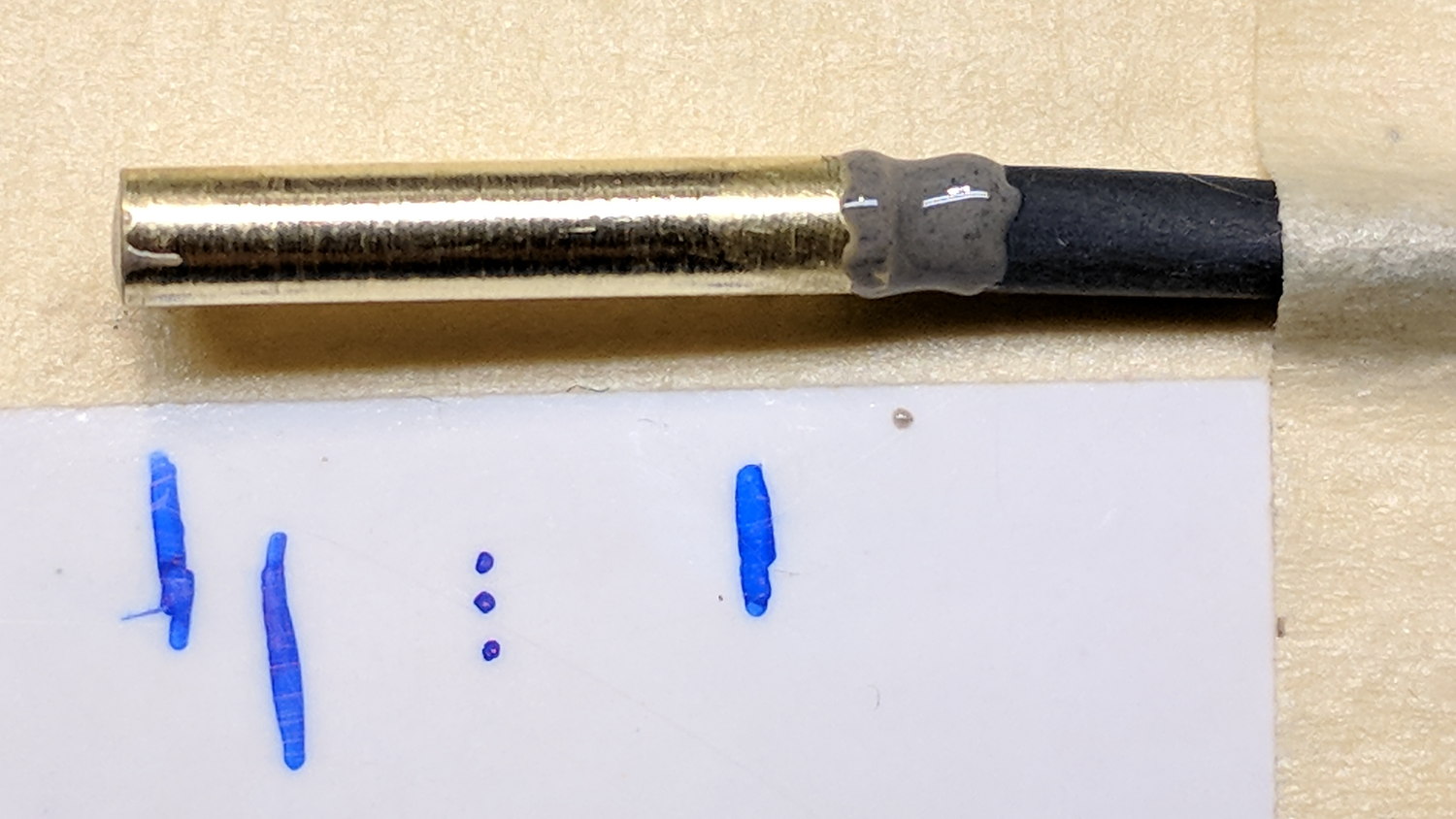
Much to my surprise, the active ingredient still worked:
M2 DIY thermistor corpse
The multimeter reported absolutely no intermittent dropouts for as long as I was willing to watch the trace while doing other things:
DIY Thermistor Autopsy – Resistance Trend
So it must be my crappy soldering technique.
A brace of real M2 thermistors will arrive shortly …
I’ve been coaching a high-school student (and his father!) on the intricacies of building a self-balancing robot; they’re doing all the hard work and I’m running interference with techie bugs. This one turned out to be particularly nasty.
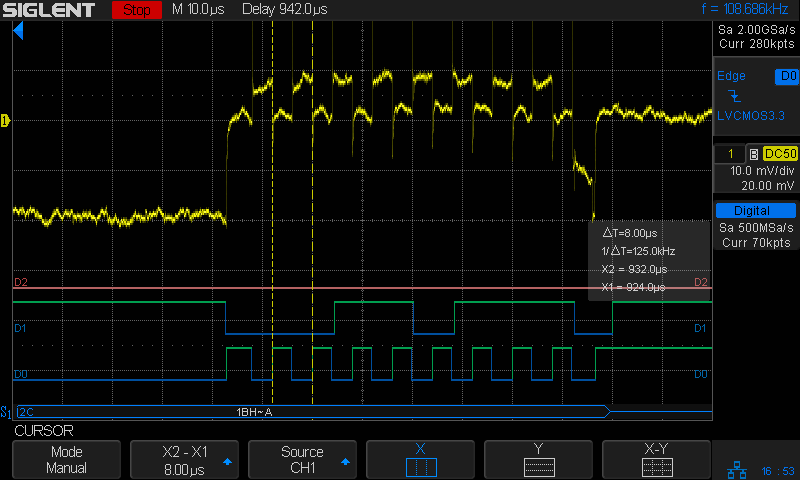
Reading the chip’s temperature sensor once every second produced this output:
BNO055 Sensor – Temperature Register vs I2C
He now knows why you must always leading-zero-fill binary values.
The shorter values say the chip ran at 26 °C, which means the longer values have a bogus binary 1 in bit 7. I2C bus transfers proceed MSB-first, so the Pi occasionally reads a bogus 1 at the first clock transition while reading the single temperature byte from the BNO055.
After some flailing around, we observed two types of I2C bus transactions.
Without clock stretching:
BNO055 – Normal I2C transaction
With clock stretching:
BNO055 – Clock-stretched I2C transaction
Contrary to what one might think from the lead-in description, the non-stretched version always produces the incorrect leading bit and the stretched version usually delivers the correct result.
He had previously installed the clock stretch workaround and we verified it was active. Turning it off had no effect, as did turning it back on again. The value uses units of the SCL period, so the modified value of 20000 produces 20×103 counts of 1/(100 k bit/s) = 2 s, far longer than any delay we observed. In fact, the default 640 μs would (apparently) suffice for the BNO055.
We noticed, but I did not record, nasty positive-going pulses on both SDA and SCL which were not due to noise or supply problems. As far as I can tell, the Pi does not maintain control over the I2C bus lines during some phases of the transaction, perhaps when the BNO055 invokes clock stretching, allowing the pullups to produce narrow upward glitches crossing the logic threshold. This will merit further study.
The solution, such as it is, seems to require slowing the I2C bus transactions to 25 kb/s, by inserting a line in the /boot/config.txt file:
dtparam=i2c_arm_baudrate=25000 ... dummy line to reveal underscores ...
Slowing to 50 kb/s produced intermittent errors, while 25 kb/s seemed to completely eliminate them. This contradicts suggestions of proper operation at any speed other than the default 100 kb/s. Note: this applies to a single-byte data value and longer transactions remain to be tested.
I want to verify that the lower rate also eliminates the glitches, which will require running the Pi with the scope plumbed into its guts for some time. For obvious reasons, he’d rather get the robot working, so, until he encounters more problems, I won’t see the hardware …
Update: There’s now a way to do I²C with software bit-banging in a reasonably easy way. Thanks to Simon Blake for pointing this out!
The pedal on one of Mary’s Kenmore Model 158 sewing machines lost most of its speed control abilities, which past experience has shown indicates its carbon / graphite disks have deteriorated. Fortunately, I still have a supply of disks from the Crash Test Dummy machine and have gotten pretty good at dismantling the pedal housing.
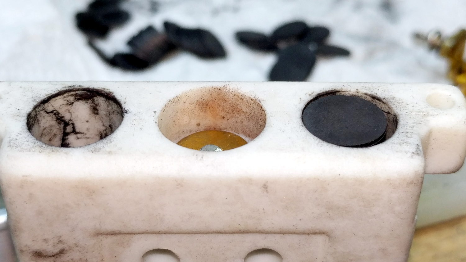
While I had the pedal apart, I filed the brass contact plates smooth again:
Kenmore 158 Pedal – graphite disk contact
Most of the deterioration happens within half a dozen disks snuggled up against those contacts, a few more on the other end of the stack against the graphite button applying the pressure, and an occasional grimy disk in the middle of the stack.
I filled both stacks flush to the top of the ceramic housing, then removed one disk from each to let the brass contacts slightly compress the stacks:
Kenmore 158 Pedal – graphite disk refill
A quick test showed the control range started a bit too fast, so I removed one more disk from the stacks, buttoned it up, and it’s all good again: a slow start with a good range.
The Description sounds enticing, in the usual eBay manner:
100% Brand new and high quality.
Product Shape: Same as the picture show
1. Product Name: High Voltage Alligator Clip Test Leads
2. Cable Type: Double-Ended Wire
3. Conductor Material& Size: 1mm²Copper Wires
4. Housing Material: Silicone
5. Max. Current: 15A
6. Withstanding Voltage: 2KV
7. Operating Temperature: -20℃~120℃
8. Making Way: Injection Molding
9. Interface Type: AC/DC
10. Color: Black, Yellow, Red, Green, Blue
Suit For:
1. Injection molding to complete, good looking, moisture proof, durable and tough!
2. Electrical test leads suitable for use with multimeters, power supplies and other electronic equipment
They’re three bucks each, which should buy you some copper and decent construction.
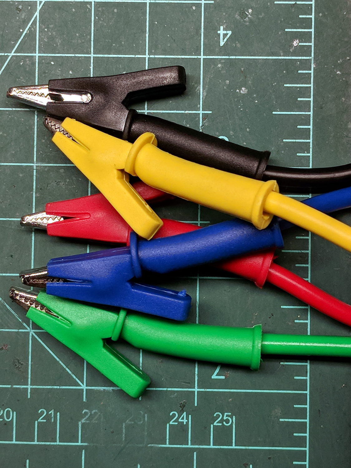
The insulation over the clips is certainly chunky enough, even if one might quibble about the standoff distance required for a 2 kV rating:
eBay HV Alligator Clips – overview
The wires have good silicone insulation and consist of fine copper strands, but I definitely won’t trust them to handle 2 kV:
eBay HV Alligator Clips – wiring
No solder, of course, just copper conductors bent back around the insulation and crimped into the alligator clip. Definitely not a gas-tight metal-to-metal joint, but good enough for simple needs.
Update: A better look at the crimp on a different clip:
eBay HV Alligator Clips – crimp
IMO, the clip’s low-strength metal can’t possibly make and hold a gas-tight joint, no matter how hard you squeeze.
There’s enough contact area for low resistance, on the order of a few tens of milliohms. We’ll see how long this lasts …
One of my Tektronix AM503 Hall Effect Current Probe Amplifiers (B075593, for future reference) lost its DC Level zero-ing capability:
Tek AM503 front panel
The front-panel knob produced only positive output voltages from maybe 50 mV to the amp’s upper limit around 200 mV (into a 50 Ω termination, Tek not being one to fool around with signal quality & bandwidth). Other than that, the amp seemed to work fine, but you definitely want a 0 V baseline corresponding to no current through the Hall probe.
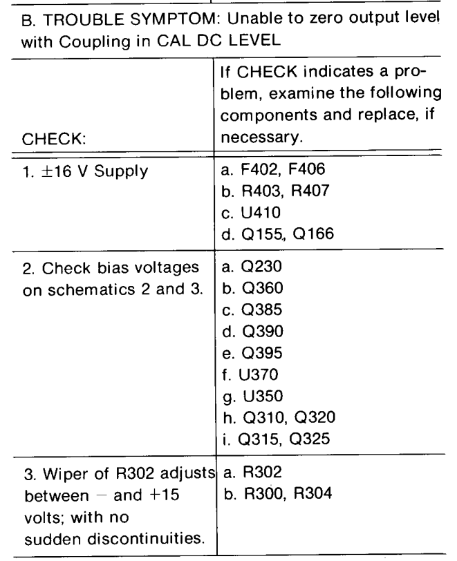
The manual includes troubleshooting recommendations:
Tek AM503 Amplifier – troubleshooting zero set problems
Because I didn’t understand the circuitry, I check the supply voltages, then started at U350, the differential amp rubbing the DC level knob against the input signal, and worked outward in both directions (clicky for more dots):
Tek AM503 Current Probe Amplifier – p 61 – Output Amplifier schematic
The PCB looks like this:
Tek AM503 – Q230 PCB detail
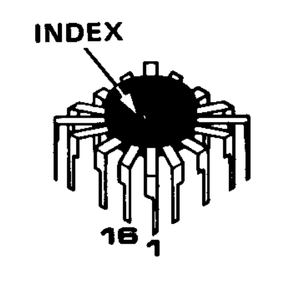
U350 is the round epoxy package in the the square spider-leg array over on the far left. Contrary to what you (well, I) might think, the index mark denotes pin 16, not pin 1:
Tek AM503 Amplifier – Tek-unique IC pinout reference
Which puts pin 1 at the upper right corner of the package on the PCB. The part listing in the manual says MICROCKT,LINEAR:VERTICAL AMPLIFIER / SELECTED, which makes perfect sense given Tek’s oscilloscope business; if you needed a high-speed differential amplifier, that’s what Tek’s internal catalog would surely suggest. Newer AM503 revisions use somewhat less unobtainable op amps, although they replace the DC Level knob with one of those newfangled microcontroller thingies for some sweet auto-leveling action.
Nothing seemed out of order. The unable-to-zero condition pushed the bias voltages off the expected values, but nothing seemed completely out of whack / stuck at the rails / broken.
The problem turned out to be in Q230, the first item on Tek’s checklist after the power supplies, even though its bias voltages looked OK. It produces the “Attenuated AC Signal” seen above and lives on another page of the schematics:
Tek AM503 Amplifier – Q230 detail
Q230 is clad in the natty red heatsink in the PCB picture above. CR226 is the metal TO-18-ish can partially hidden by the orange-red-brown ribbon cable from the DC Level pot.
For future reference, C234 and C244 aren’t installed in this PCB; they’d fit in the conspicuously vacant spots to the right and in front of Q230.
What may not be obvious at a first glance: Q230’s pins sit in teeny individual sockets installed in the PCB. One might remove and reinstall Q230, should one be so inclined and, given that it’s the first active device after the input attenuator, one might imagine such an action being necessary after a catastrophic oopsie.
At this late date, finding a suitable dual JFET would be … difficult, even were one were willing to compromise on the hermetic metal TO-78A package.
Seeing as how Q230 has been sitting quietly in its socket for the last three decades, I proceeded cautiously:
Turned the power off
Waited for the supply voltages to drop
Pulled Q230 slightly upward
Wiggled-and-jiggled it around
Shoved it back down
Turned the power on
I heroically refrained from pulling it completely out of its socket to dab DeoxIT on the pins; JFETs being notorious for susceptibility to static damage and, likely, lube would make no difference anyway.
Fired that devil up and the DC Level knob resumed doing exactly what it should:
Tek AM503 – Q230 reseated
The output now has the usual ±200 mV range centered at 0 V. The waveform shows a 100 mA signal at 50 mA/div, produced by a bench supply into a 100 Ω power resistor switched by a DC-DC SSR.
Ex post facto notes from the fourth Squidwrench Electronics Workshop.
We finally talk about (bipolar, NPN) transistors as current-controlled current sources / sinks, ruthlessly restricted to DC operating conditions.
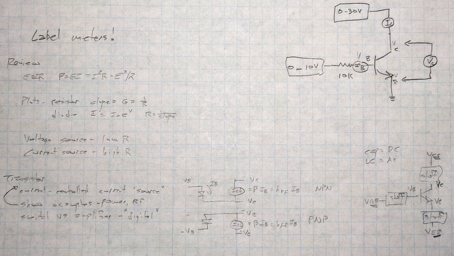
Scribbled notes of things to cover, contrast-stretched to be slightly more readable:
Session 4 – plan reminder
A bag o’ samples:
Session 4 – transistor samples
Nomenclature, regret expressed as to conventional vs electron current flow, schematic pictures vs. reality, why different packages. All six possible pinouts loose in the wild: always check datasheet and confirm device pin polarity.
Not all TO-92 packages contain transistors: voltage regulators, references, AM receivers, dual diodes, you name it, you’ll find it. When you order a million of something, you can get whatever you want.
The Squidwrench junk box parts drawers contain some genuine Mil-Spec 2N2222 transistors in genuine TO-18 metal cans, packed in individual containers labeled with their warranty expiration date. They still make ’em like that, just not for the likes of mere mortals such as I.
Reading data sheets and tamping down optimism: (large print) max voltage and max current ratings always limited by (small print) max power dissipation. Safe Operating Area bounded by datasheet limits, power becomes graceful curve on linear scales = straight line on log-log scales. Handwaving description of secondary breakdown issues, story about killing those ET227 bricks.
DC current gain β = hFE, font flourish catastrophes, uppercase subscripts = DC vs. lowercase = AC, temperature dependence, process dependence, expected spread = don’t count on any particular values.
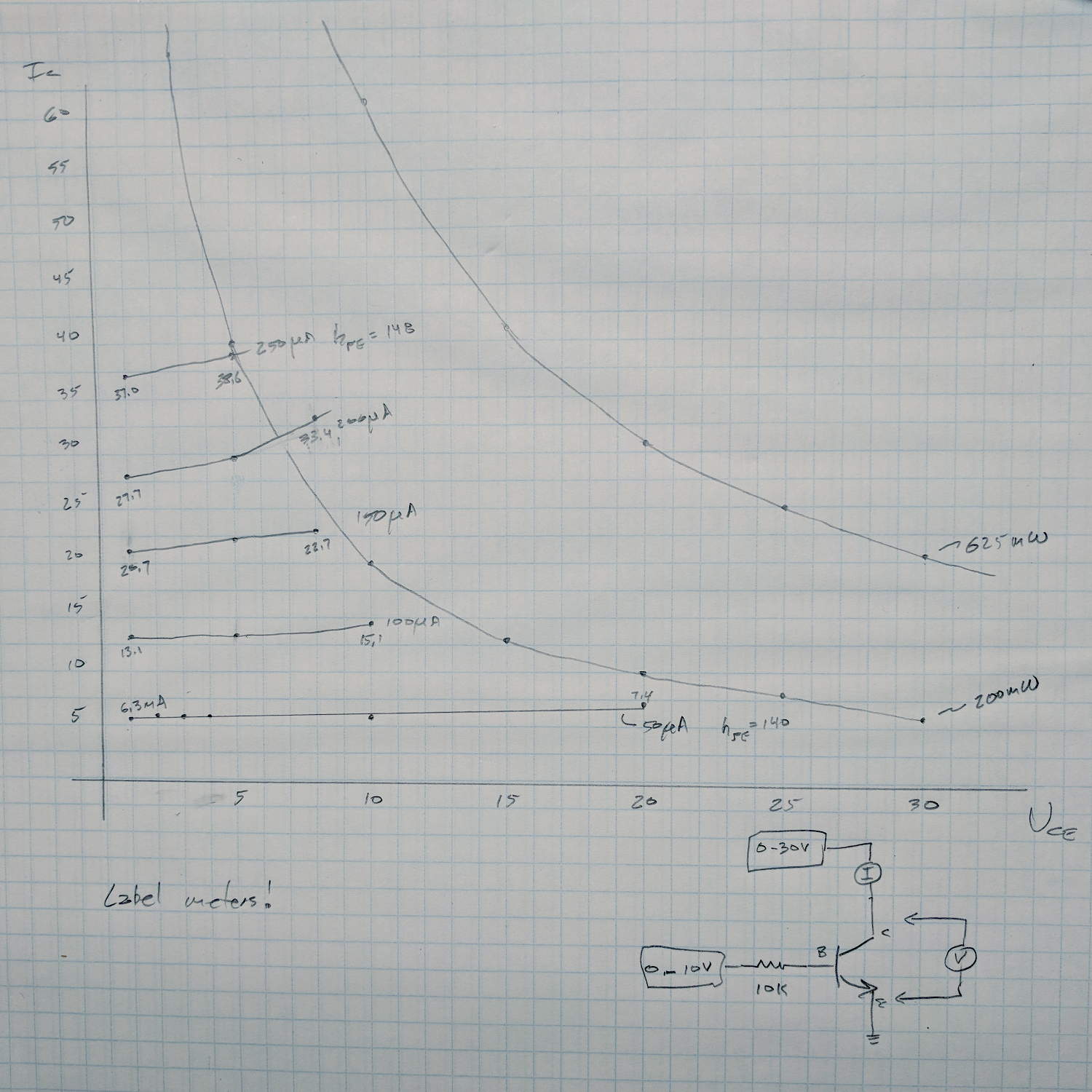
Just to show what the results should look like, I measured an MPS3704 by hand before class:
MPS3704 transistor I vs V plots
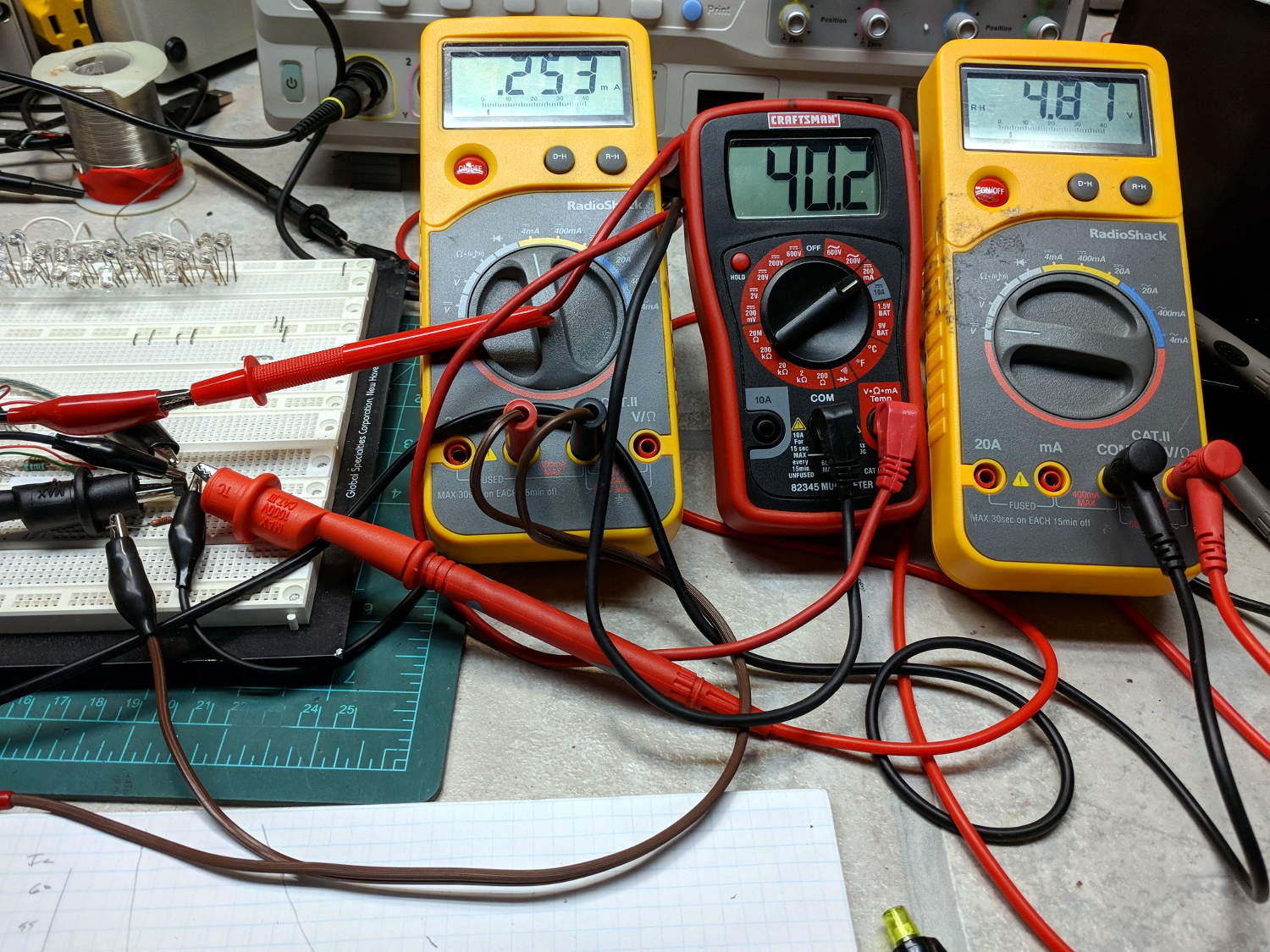
Which required two power supplies and three meters:
Session 4 – transistor measurement meters
Which, in turn, prompted me to festoon the class meters with conspicuous masking tape labels!
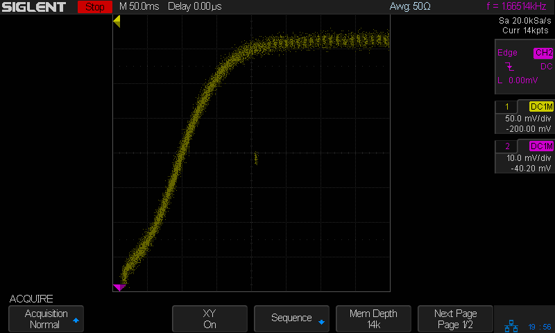
Seen a bit closer to the origin, with a fixed 100 μA base current and the scope’s arbitrary function generator producing a voltage ramp:
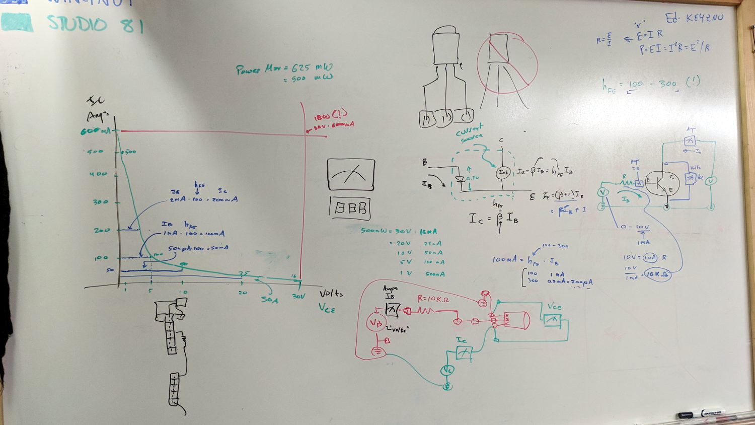
The whiteboard of introductory scribbles, with a plot of expected results:
Whiteboard – Session 4 – transistor I vs V plot
Small values of collector voltage to remain within allowable power dissipation! Discussion of switching behavior: high current at low voltage, low current at high voltage, avoid crossing the non-SOA (pulse vs DC) expanse, another mention of secondary breakdown.
After painstakingly measuring another MPS3704, compute actual current gain(s) and power dissipation:
Whiteboard – Session 4 – transistor measurements
With data in hand, we carefully increased the collector voltage with constant base current, ventured slowly into the non-SOA, and eventually measured the same base current producing no collector current at all. No smoke, much to the disappointment of all parties.
The benefit of actually measuring a (sacrificial) transistor cannot be overstated. Lots of baling-wire setup, plenty of mistakes and fumbles, hard lessons in how difficult it is to get useful numbers.
A good time was had by all, despite the absence of non-SOA smoke …
Baofeng UV-5 radios can (mostly) eliminate the loud hiss heard at the end of a transmission before the squelch kicks in after the received carrier drops: Menu → 34 STE → ON. A detailed description of the option suggests it’s a 55 Hz subaudible tone sent for 250 milliseconds after the sender releases the PTT and before the transmitter stops sending, with the receiver muting its audio during the tone. Obviously, this requires a Baofend radio at each end of the conversation, which applies to our bikes.
Saying “laaaa” while kerchunking (into a smaller dummy load than the hulk) with STE OFF:
Baofeng – STE OFF – laaaa
Compared to the received audio, the squelch tail hiss is really really loud.
Then with STE ON:
Baofeng – STE ON – laaaa
You can see the STE tone reception start about 250 ms before the audio cuts off, although it’s not at all clear the audio is muted on either end. In any event, there’s no squelch tail worth mentioning, even if there’s an audible tick when the STE tone starts.
Saying nothing with STE ON:
Baofeng – STE ON – silent
It’s unlikely the audio output would include the subaudible tone, but you might convince yourself something happens in the 250 ms between the STE blip near midscreen and the final pop (now clipped) as the audio drops.