The Smell of Molten Projects in the Morning

Ed Nisley's Blog: Shop notes, electronics, firmware, machinery, 3D printing, laser cuttery, and curiosities. Contents: 100% human thinking, 0% AI slop.

Category: Electronics Workbench

Electrical & Electronic gadgets

  • Water Cooled Stepper Motors: Flow Calculation

    A discussion on the Makergear Google Group about a heated enclosure prompted me to run the numbers for cooling stepper motors with water, rather than fans and finned heatsinks.

    The general idea comes from my measurements of the air-cooled heatsink stuck to a stepper’s end cap. The metal-to-metal conductivity works surprisingly well and reduces the case temperature to slightly over ambient with decent airflow through the heatsink; epoxying a cold plate to the end cap should work just as well. A NEMA 17 stepper case is 42.3 mm square, so a standard 40 mm square CPU cooling plate will fit almost exactly.

    The question then becomes: how much water flow do you need to keep the motors cool?

    Some numbers:

    • Water’s heat capacity is 4.2 J/g·K
    • 1 J = 1 W·s, 1 W = 1 J/s
    • NEMA 17 motors dissipate about 5 W (13 W if you’re abusing them)
    • We’ll cool all four motors in parallel, for a total of 20 W
    • Allow a 5 K = 5 °C temperature rise in each cold plate

    Rub them all together:

    (20 J/s) / (5 K * (4.2 J/g·K)) = 0.95 g/s

    For water, 1 g = 1 cc, so the total flow is 1 cc/s = 3600 cc/h = 3.6 liter/h, which, here in the US, works out to a scant 1 gallon/hour. It’s tough getting a pump that small and cheap flowmeters run around 0.5 liter/m…

    If you don’t want a pump. put an aquarium up on a (sturdy) shelf and drain it through the cold plates. A cubic foot of water, all eight gallons and sixty-some-odd pounds of it, will last 8 hours, which should be enough for most printing projects.

    If you want reliability, drain the coolers into a sump with a float switch (high = on), put another float switch (high = off) on the aquarium, and have the pump top up the aquarium. If the pump fails, your steppers stay cool for the next 8 hours. Heating the water about 5 °C during 8 hours won’t require active cooling.

    Now, managing the hoses leading to the X axis stepper may be challenging, but a cable drag chain would control the rest of the wiring, too.

  • External DVD Battery Pack Status

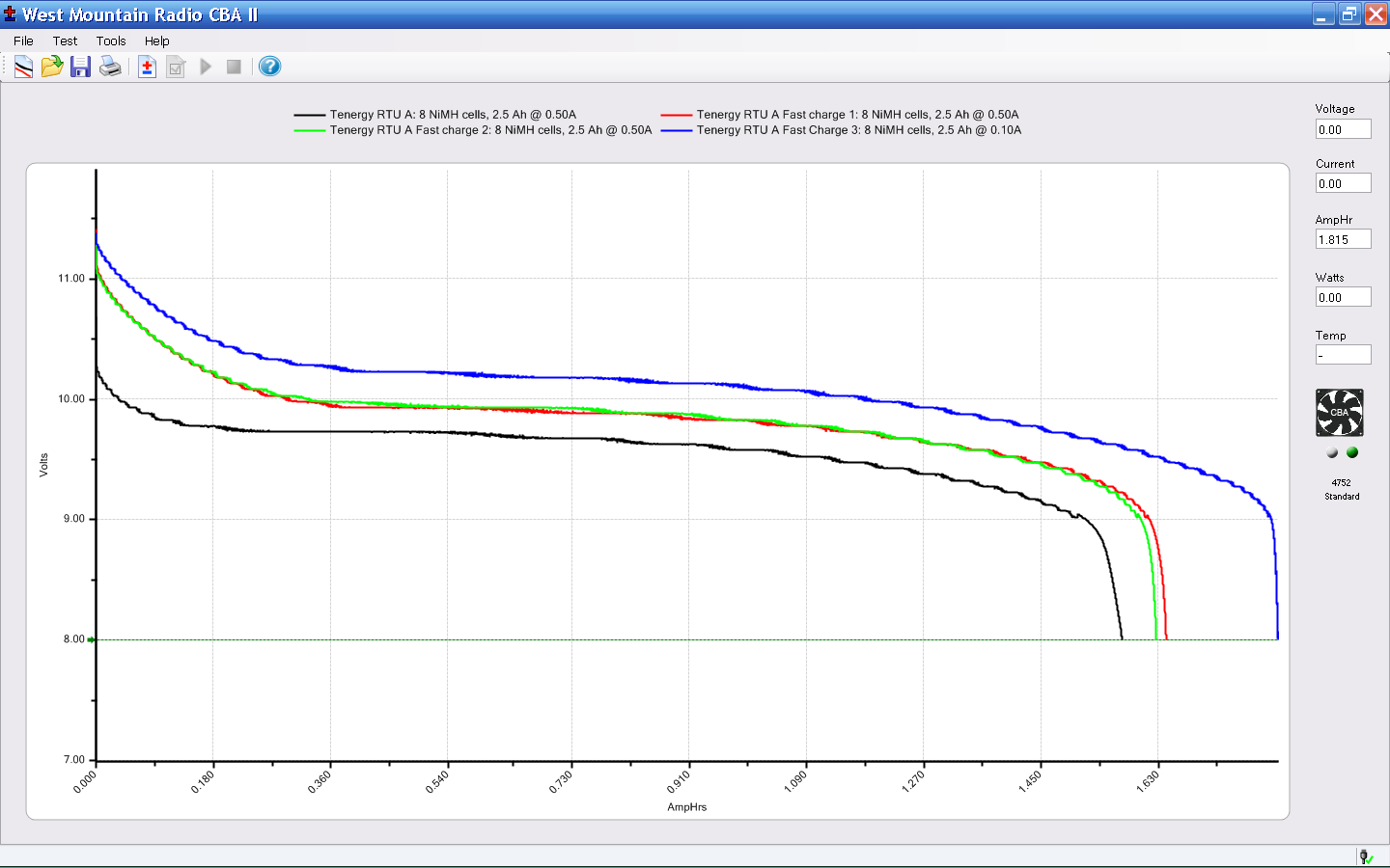
    One of the battery packs powering the GPS+audio interface on our bikes has completely failed, with zero volts at the output and no charge indication. The other five chug along as well as can be expected:

    Initial-brand DVD External Packs - 2013-11
    Initial-brand DVD External Packs – 2013-11

    The push-to-test button on Pack 4 has become increasingly erratic over the last few months, rendering the charge status LEDs mostly useless, so it has two curves: the lower capacity came directly from the bike, the higher hot off the charger.

    For reference, here’s what they looked like in May 2012:

    External Li-Ion packs - 2012-05
    External Li-Ion packs – 2012-05

    And right after they arrived:

    Initial External Li-Ion packs
    Initial External Li-Ion packs

    Given their nearly constant use and charge cycling, I’m impressed.

    Those Lenmar DVDU923 packs look similar, at twice the no-name 2010 price. So it goes…

  • Sony NP-FS11 Battery Status & Rebuild

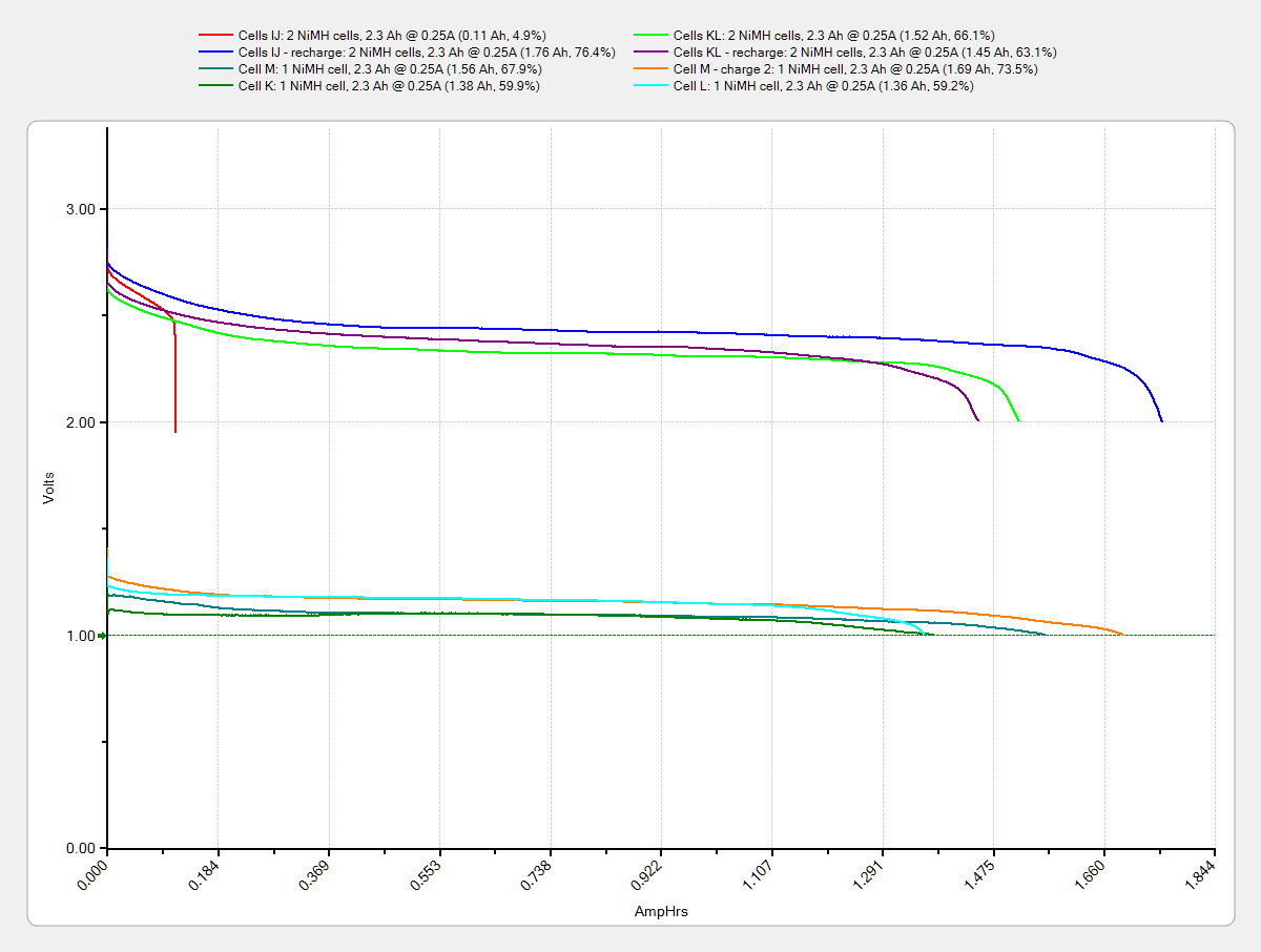
    The trio of batteries I built for the Sony DSC-F505V two years ago faded away; that camera seems particularly hard on the batteries, perhaps because they’re two cells in parallel that don’t share well. Two of the three seem pretty well gone:

    Sony NP-FS11 2011 Packs - 2013-11 tests
    Sony NP-FS11 2011 Packs – 2013-11 tests

    Back then, I bought 12 cells, built six into those batteries, and left six charged cells sitting in a bag. After rebuilding the two worst batteries with those new-old-stock cells, it seems they maintained a substantial fraction of their charge while resting in the cool and the dark:

    Sony NP-FS11 2011 Cells - 2013 packs - 2013-11-24
    Sony NP-FS11 2011 Cells – 2013 packs – 2013-11-24

    However, the camera would regard them as discharged, because it infers charge state from voltage. Squinting at the curves, their condition after a few minutes is roughly equal to a new & freshly charged battery produces over on the right when it’s nearly discharged.

    The other curves show the result after their first charge in two years: basically, full capacity. The fact that both pairs of curves come pretty close to overlaying means they’re still well matched.

    Sony NP-FS11 batteries - rebuilt
    Sony NP-FS11 batteries – rebuilt

    The third cell isn’t up to their spec, but it’s close enough to not bother rebuilding right now: 1.2 vs 1.4 A·h.

    The Kapton tape pull tabs work wonderfully well, as the rebuilt batteries fit the compartment rather more snugly than the un-hacked cases.

  • Canon NB-5L Battery Status

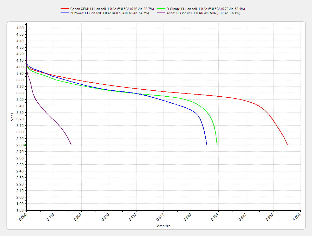
    One of the junker NB-5L eBay batteries for my Canon SX-230HS pocket camera gave up, but the other two have some usable capacity left. The OEM Canon battery seems to be doing fine, perhaps because it sees a relatively low duty cycle:

    Canon NB-5L - 2013-11
    Canon NB-5L – 2013-11

    Compare those curves with the previous tests:

    Canon NB-5L - 2011-08-26
    Canon NB-5L – 2011-08-26

    I harvested the weakest of the four junkers to make that dummy battery.

    It’s about time to pick up a few more junkers: alas, I can find no bare cells in a size to fit that case.

  • Hall Effect Current Control PCB: Voltage Variations

    The whole point of the Hall effect current sensor was to get a reasonably efficient linear LED driver that could control the LED current until the battery voltage matched the LED forward drop. Based on the preliminary firmware, it works pretty well.

    With a setpoint of 160 mA, the current stabilizes around 150 mA due to the Arduino’s 0.4% PWM resolution. It steps back and forth between 150 and 190 mA as the loop bumps the PWM by one count; these scope shots came from the lower current passes.

    At 8.4 V from the bench supply, the MOSFET sees about 2 V. The top trace is the drain voltage, the bottom is LED current at 50 mA/div:

    VIN 8.4 V - VD ILED 50 mA-div
    VIN 8.4 V – VD ILED 50 mA-div

    At 7.4 V, close to the nominal voltage during most of the discharge curve, the drain sees about 1 V:

    VIN 7.4 V - VD ILED 50 mA-div
    VIN 7.4 V – VD ILED 50 mA-div

    And at 6.4 V, even though the drain voltage hits zero, the current remains around 150 mA:

    VIN 6.4 V - VD ILED 50 mA-div
    VIN 6.4 V – VD ILED 50 mA-div

    Admittedly, down there the loop doesn’t have much in the way of control authority, but I planned to turn the lights out at about that point, anyway.

    The driver efficiency is 86% at 7.4 V and it’s pretty nearly 100% at 6.4 V.

    Of course, the Hall effect circuitry and Arduino Pro Mini soak up another 40 mA or so, so (assuming a 10% duty cycle) the overall efficiency is down around 70%, but that’s including the debugging LEDs and suchlike, so some tweaking is in order.

  • HP Scope Probe Flange Repair: Improved Spares

    While reducing the clutter atop the Electronics Workbench, I ran off four more probe flange reinforcements, just so I’m ready for the next crunch:

    HP scope probe flange disks
    HP scope probe flange disks

    They’re almost identical to the previous version, although I tweaked the taper to end slightly inside the cylindrical cup, thereby eliminating the coincident faces and leaving a minute rim that doesn’t matter:

    HP Scope Probe Flange Repair - bottom
    HP Scope Probe Flange Repair – bottom

    Given that I’ve had the ‘scope for nigh onto two decades and have only broken one probe flange, I think four reinforcements will be a lifetime supply: with any luck, the scope will blow a capacitor before I do.

    The OpenSCAD source code:

    // Tek Scope Probe Flange
    // Ed Nisley KE4ZNU November 2013
    
    //- Extrusion parameters must match reality!
    //  Print with 2 shells and 3 solid layers
    
    ThreadThick = 0.20;
    ThreadWidth = 0.40;
    
    HoleWindage = 0.2;
    
    Protrusion = 0.1;            // make holes end cleanly
    
    function IntegerMultiple(Size,Unit) = Unit * ceil(Size / Unit);
    
    //----------------------
    // Dimensions
    
    FlangeOD = 16.0;
    FlangeID = 8.75;
    FlangeThick = IntegerMultiple(1.25,ThreadThick);
    
    DiskOD = FlangeOD + 4*ThreadWidth;
    DiskThick = FlangeThick + 4*ThreadThick;
    
    NumSides = 8*4;
    
    //----------------------
    // Useful routines
    
    module PolyCyl(Dia,Height,ForceSides=0) {            // based on nophead's polyholes
    
    Sides = (ForceSides != 0) ? ForceSides : (ceil(Dia) + 2);
    
    FixDia = Dia / cos(180/Sides);
    
    cylinder(r=(FixDia + HoleWindage)/2,
    h=Height,
    $fn=Sides);
    }
    
    module ShowPegGrid(Space = 10.0,Size = 1.0) {
    
    Range = floor(50 / Space);
    
    for (x=[-Range:Range])
    for (y=[-Range:Range])
    translate([x*Space,y*Space,Size/2])
    %cube(Size,center=true);
    
    }
    
    //----------------------
    // Build it
    
    ShowPegGrid();
    
    difference() {
    union() {
    translate([0,0,2*ThreadThick])
    cylinder(r=DiskOD/2,h=DiskThick,$fn=NumSides);    // cylinder around flange
    
    cylinder(r1=(DiskOD - 2*ThreadWidth)/2,                // flange reinforcing plate
    r2=DiskOD/2,
    h=(2*ThreadThick + Protrusion),
    $fn=NumSides);
    }
    translate([0,0,(DiskThick - FlangeThick)])                // flange clearance
    PolyCyl(FlangeOD,2*FlangeThick,NumSides);
    
    translate([0,0,-DiskThick/2])                            // probe nose clearance
    PolyCyl(FlangeID,2*DiskThick,NumSides);
    }
    
  • Arduino Analog Input Averaging

    The Hall effect LED current controller measures a bunch of analog signals that have a lot of PWM ripple, so I average ten readings:

    //-- Read AI channel
    //      averages several readings to improve noise performance
    //		returns value in volts assuming known VCC ref voltage
    
    #define NUM_T_SAMPLES    10
    
    float ReadAI(byte PinNum) {
    
      word RawAverage;
    
      digitalWrite(PIN_SYNC,HIGH);					// scope sync
    
      RawAverage = (word)analogRead(PinNum);		// prime the averaging pump
    
      for (int i=2; i <= NUM_T_SAMPLES; i++) {
        RawAverage += (word)analogRead(PinNum);
      }
    
      digitalWrite(PIN_SYNC,LOW);
    
      RawAverage /= NUM_T_SAMPLES;
    
      return Vcc * (float)RawAverage / 1024.0;
    
    }
    

    The PIN_SYNC output produces the upper trace, with the LED current in the lower trace at 50 mA/div:

    Arduino Analog 10x sample avg - ILED 50 mA-div
    Arduino Analog 10x sample avg – ILED 50 mA-div

    In round numbers, ten samples require 1.1 ms and cover about 35 PWM pulses (using 32 kHz PWM, as you really should if you need an actual analog voltage).

    Because the samples occur asynchronously with respect to the PWM pulses, the computed average comes out surprisingly close to the actual average. Fewer samples would probably be just as good, but I’m in no hurry.