They may have added a block heater since I took that picture, but warm moist air will always condense on cold metal and glass:

It really needs a dehumidifier…
The Smell of Molten Projects in the Morning
Ed Nisley's Blog: Shop notes, electronics, firmware, machinery, 3D printing, laser cuttery, and curiosities. Contents: 100% human thinking, 0% AI slop.
Electrical & Electronic gadgets
They may have added a block heater since I took that picture, but warm moist air will always condense on cold metal and glass:

It really needs a dehumidifier…
The Sony HDR-AS30V “action camera” uses NP-BX1 lithium batteries (3.7 V @ 1.24 A·h = 4.6 W·h) that are, of course, a completely different size and shape than any other lithium battery on the planet.
So.
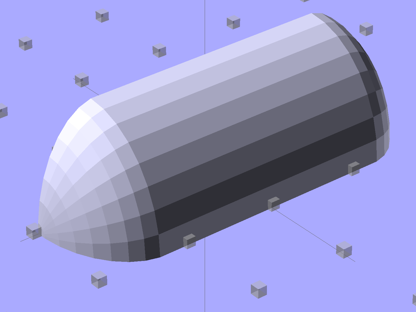
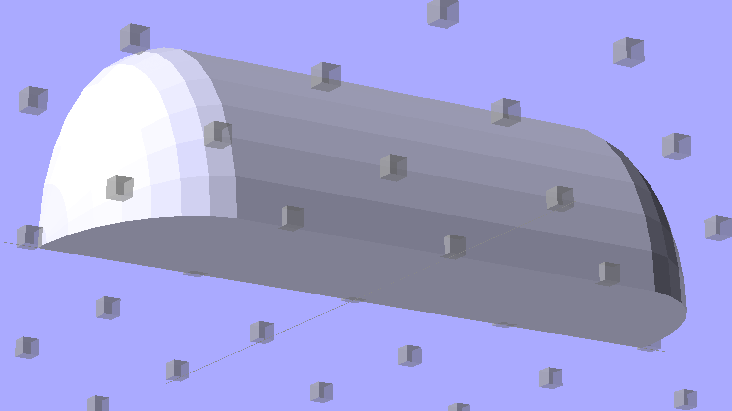
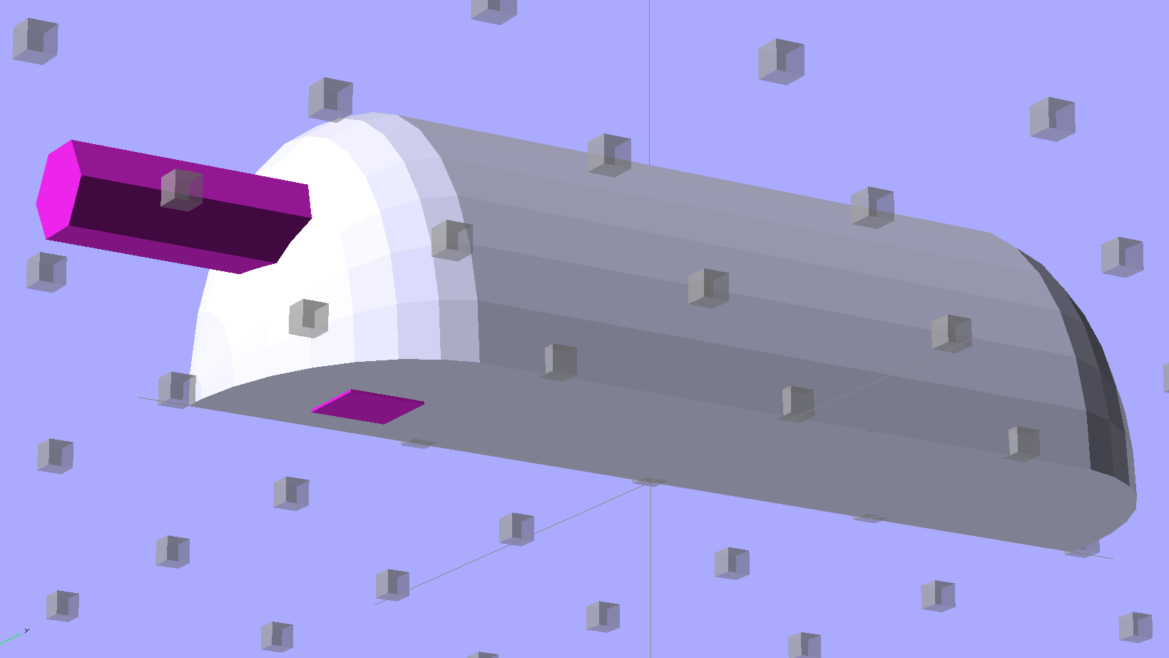
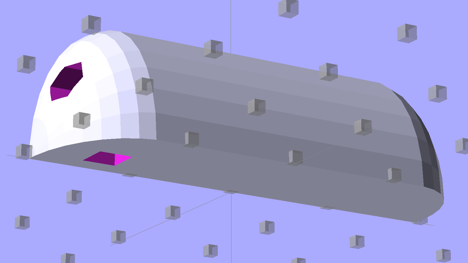
Tweaking a few dimensions in the Canon NB-6L source code, tinkering with the layout of the contact pins, and shazam Yet Another 3D Printed Battery Test Fixture:

It builds nicely, although the contact pin tunnels are a bit too close to the top of the case:

After reaming out the contact pin holes to the proper diameters & depths, then gluing the plugs in place, it works just as you’d expect:

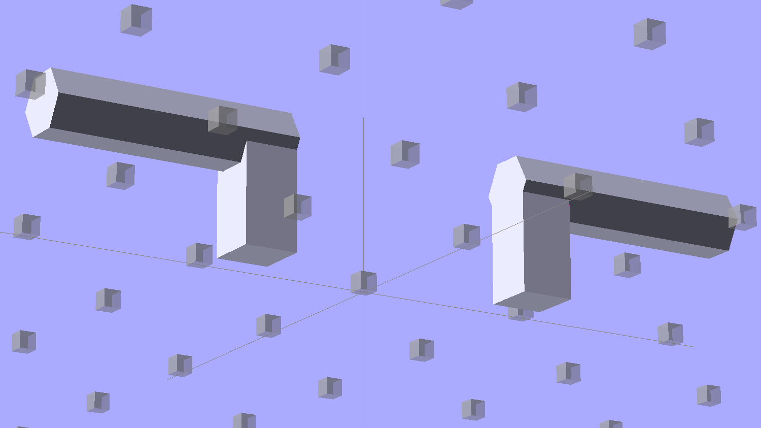
It’s worth noting that the Wasabi charger accepts the batteries upside-down, with the conspicuous chevron against the charger body. It’s definitely not the way all the other chargers work. The keying recesses on the battery (corresponding to the blocks in the solid model) lie along the bottom edge of the contact surface, so flipping the battery over means they’ll hold it in place, but … oh, well.
That grotty Powerpole connector last saw use in some random benchtop lashup. At some point I’ll be forced to start making more of those.
The OpenSCAD source code:
// Holder for Sony NP-BX1 Li-Ion battery
// Ed Nisley KE4ZNU January 2013
include <MCAD/boxes.scad>
// Layout options
Layout = "Show"; // Show Build Fit Case Lid Pins Plugs AlignPins
//- Extrusion parameters - must match reality!
// Print with +2 shells and 3 solid layers
ThreadThick = 0.20;
ThreadWidth = 0.40;
HoleWindage = 0.2;
function IntegerMultiple(Size,Unit) = Unit * ceil(Size / Unit);
Protrusion = 0.1; // make holes end cleanly
inch = 25.4;
BuildOffset = 3.0; // clearance for build layout
Gap = 8.0; // separation for Fit parts
//- Battery dimensions - rationalized from several samples
// Coordinate origin at battery corner by contact plates on bottom surface
BatteryLength = 43.0;
BatteryWidth = 30.0;
BatteryThick = 9.5;
ContactWidth = 2.90;
ContactLength = 4.30;
ContactRecess = 0.90;
ContactOC = 10.0; // center-to-center across contact face
ContactOffset = 6.20; // offset from battery edge
ContactHeight = 6.30; // offset from battery bottom plane
AlignThick = 2.75; // alignment recesses on contact face
AlignDepth = 1.70; // into face
AlignWidth1 = 3.70; // across face at contacts
AlignWidth2 = 3.60; // ... other edge
//- Pin dimensions
PinTipDia = 1.6;
PinTipLength = 10.0;
PinTaperLength = 2.3;
PinShaftDia = 2.4;
PinShaftLength = 6.8;
PinFerruleDia = 3.1;
PinFerruleLength = 2.0;
PinLength = PinTipLength + PinTaperLength + PinShaftLength + PinFerruleLength;
ExtendRelax = 1.5 + ContactRecess; // pin extension when no battery is present
ExtendOvertravel = 1.0; // ... beyond engaged position
//- Spring dimensions
SpringDia = 3.1; // coil OD
SpringMax = 9.3;
SpringLength = SpringMax - 0.5; // slightly compressed
SpringMin = 4.5;
SpringPlugOD = IntegerMultiple(5.0,ThreadWidth); // plug retaining the spring
SpringPlugID = 2.0;
SpringPlugLength = IntegerMultiple(4.0,ThreadWidth);
SpringPlugSides = 3*4;
SpringTravel = ExtendRelax + ExtendOvertravel;
//- Holder dimensions
GuideRadius = ThreadWidth; // friction fit ridges
GuideOffset = 7; // from compartment corners
WallThick = 4*ThreadWidth; // holder sidewalls
BaseThick = 6*ThreadThick; // bottom of holder to bottom of battery
TopThick = 6*ThreadThick; // top of battery to top of holder
ThumbRadius = 10.0; // thumb opening at end of battery
CornerRadius = 3*ThreadThick; // nice corner rounding
CaseLength = SpringPlugLength + SpringLength + PinLength - ExtendRelax
+ BatteryLength + GuideRadius + WallThick;
CaseWidth = 2*WallThick + 2*GuideRadius + BatteryWidth;
CaseThick = BaseThick + BatteryThick + TopThick;
AlignPinOD = 1.75; // lid alignment pins - filament snippets
AlignPinLength = 5.0;
AlignPinInset = 7.0;
AlignPinOffset = -3.75; // from centerline - choose to miss contact pins
//- XY origin at front left battery corner, Z on platform below that
CaseLengthOffset = -(SpringPlugLength + SpringLength + PinLength - ExtendRelax);
CaseWidthOffset = -(WallThick + GuideRadius);
CaseThickOffset = BaseThick;
LidLength = ExtendRelax - CaseLengthOffset;
echo(str("Contact pin tip dia: ",PinTipDia));
echo(str("Drill depth to taper end: ",
(SpringPlugLength + SpringLength + PinFerruleLength + PinShaftLength + PinTaperLength),
" -- Dia: ",PinShaftDia));
echo(str(" to ferrule end: ",
(SpringPlugLength + SpringLength + PinFerruleLength),
" -- Dia: ",PinFerruleDia));
echo(str(" to plug end: ",SpringPlugLength,
" -- Dia: ",SpringPlugOD));
//----------------------
// Useful routines
module PolyCyl(Dia,Height,ForceSides=0) { // based on nophead's polyholes
Sides = (ForceSides != 0) ? ForceSides : (ceil(Dia) + 2);
FixDia = Dia / cos(180/Sides);
cylinder(r=(FixDia + HoleWindage)/2,
h=Height,
$fn=Sides);
}
module ShowPegGrid(Space = 10.0,Size = 1.0) {
Range = floor(50 / Space);
for (x=[-Range:Range])
for (y=[-Range:Range])
translate([x*Space,y*Space,Size/2])
%cube(Size,center=true);
}
//-------------------
//-- Guides for tighter friction fit
module Guides() {
translate([GuideOffset,-GuideRadius,CaseThickOffset])
PolyCyl(2*GuideRadius,(BatteryThick - Protrusion),4);
translate([GuideOffset,(BatteryWidth + GuideRadius),CaseThickOffset])
PolyCyl(2*GuideRadius,(BatteryThick - Protrusion),4);
translate([(BatteryLength - GuideOffset),-GuideRadius,CaseThickOffset])
PolyCyl(2*GuideRadius,(BatteryThick - Protrusion),4);
translate([(BatteryLength - GuideOffset),(BatteryWidth + GuideRadius),CaseThickOffset])
PolyCyl(2*GuideRadius,(BatteryThick - Protrusion),4);
translate([(BatteryLength + GuideRadius),GuideOffset/2,CaseThickOffset])
PolyCyl(2*GuideRadius,(BatteryThick - Protrusion),4);
translate([(BatteryLength + GuideRadius),(BatteryWidth - GuideOffset/2),CaseThickOffset])
PolyCyl(2*GuideRadius,(BatteryThick - Protrusion),4);
}
//-- Contact pins (holes therefore)
module PinShape() {
union() {
cylinder(r=(PinTipDia + HoleWindage)/2,h=(PinTipLength + Protrusion),$fn=6);
translate([0,0,PinTipLength])
cylinder(r=(PinShaftDia + HoleWindage)/2,
h=(PinTaperLength + PinShaftLength + Protrusion),$fn=6);
translate([0,0,(PinLength - PinFerruleLength)])
cylinder(r=(PinFerruleDia + HoleWindage)/2,
h=(PinFerruleLength + Protrusion),$fn=6);
translate([0,0,(PinLength)])
cylinder(r=(SpringDia + HoleWindage)/2,
h=(SpringLength + Protrusion),$fn=6);
translate([0,0,(PinLength + SpringLength - HoleWindage)]) // windage for hole length
cylinder(r=(SpringPlugOD + HoleWindage)/2,h=3*SpringPlugLength,$fn=SpringPlugSides);
// translate([0,0,(PinLength + SpringLength + SpringPlugLength)])
// cylinder(r=(SpringPlugOD + HoleWindage)/2,h=2*SpringPlugLength,$fn=SpringPlugSides); // extend hole
}
}
module PinAssembly() {
translate([ExtendRelax,ContactOffset,CaseThickOffset + ContactHeight]) {
rotate([0,270,0]) {
PinShape(); // pins
translate([0,(1*ContactOC),0])
PinShape();
}
}
}
//-- Alignment pins
module AlignPins() {
for (x=[-1,1])
translate([x*(LidLength - 2*AlignPinInset)/2,AlignPinOffset,0])
rotate(45)
PolyCyl(AlignPinOD,AlignPinLength);
}
//-- Case with origin at battery corner
module Case() {
difference() {
union() {
difference() {
translate([(CaseLength/2 + CaseLengthOffset),
(CaseWidth/2 + CaseWidthOffset),
(CaseThick/2)])
roundedBox([CaseLength,CaseWidth,CaseThick],CornerRadius); // basic case shape
translate([-ExtendOvertravel,-GuideRadius,CaseThickOffset])
cube([(BatteryLength + GuideRadius + ExtendOvertravel),
(BatteryWidth + 2* GuideRadius),
(BatteryThick + Protrusion)]); // battery space
}
Guides();
translate([-ExtendOvertravel,-GuideRadius,BaseThick])
cube([(AlignDepth + ExtendOvertravel),
(AlignWidth1 + GuideRadius),
AlignThick]); // alignment blocks
translate([-ExtendOvertravel,
(BatteryWidth - AlignWidth2),
BaseThick])
cube([(AlignDepth + ExtendOvertravel),
(AlignWidth2 + GuideRadius),
AlignThick]);
}
translate([(-ExtendOvertravel),
(CaseWidthOffset - Protrusion),
(CaseThickOffset + BatteryThick)])
cube([CaseLength,
(CaseWidth + 2*Protrusion),
(TopThick + Protrusion)]); // battery access
translate([(CaseLengthOffset - Protrusion),
(CaseWidthOffset - Protrusion),
(CaseThickOffset + BatteryThick)])
cube([(CaseLength + 2*Protrusion),
(CaseWidth + 2*Protrusion),
(TopThick + Protrusion)]); // battery insertion allowance
translate([(BatteryLength - Protrusion),
(CaseWidth/2 + CaseWidthOffset),
(CaseThickOffset + ThumbRadius)])
rotate([90,0,0])
rotate([0,90,0])
cylinder(r=ThumbRadius,
h=(WallThick + GuideRadius + 2*Protrusion),
$fn=22); // remove thumb notch
PinAssembly();
translate([-LidLength/2,BatteryWidth/2,CaseThick - TopThick - (AlignPinLength - TopThick/2)])
AlignPins();
}
}
module Lid() {
difference() {
translate([0,0,(CaseThick/2 - BaseThick - BatteryThick)])
roundedBox([LidLength,
CaseWidth,CaseThick],CornerRadius);
translate([0,0,-(CaseThick/2)])
cube([(LidLength + 2*Protrusion),
(CaseWidth + 2*Protrusion),
(CaseThick)],center=true);
translate([-ExtendRelax,0,-(AlignPinLength - TopThick/2)])
AlignPins();
}
}
module PlugShape() {
difference() {
cylinder(r=SpringPlugOD/2,h=SpringPlugLength,$fn=SpringPlugSides);
translate([0,0,-Protrusion])
PolyCyl(SpringPlugID,(SpringPlugLength + 2*Protrusion),SpringPlugSides);
}
}
module Plugs() {
translate([0,ContactOC,0])
PlugShape();
translate([0,-ContactOC,0])
PlugShape();
}
//-------------------
// Build it!
ShowPegGrid();
if (Layout == "Case")
Case();
if (Layout == "Lid")
Lid();
if (Layout == "Plugs")
for (i=[-1:1])
translate([i*1.5*SpringPlugOD,0,0])
Plugs();
if (Layout == "Pins")
PinShape();
if (Layout == "AlignPins")
AlignPins();
if (Layout == "Show") { // reveal pin assembly
difference() {
Case();
translate([(CaseLengthOffset - Protrusion),
(CaseWidthOffset - Protrusion + WallThick + ContactOffset + ContactOC),
(BaseThick + ContactHeight)])
cube([(-CaseLengthOffset + Protrusion),
(CaseWidth + 2*Protrusion),
CaseThick + BaseThick - ContactHeight + Protrusion]);
translate([(CaseLengthOffset - Protrusion),
(CaseWidthOffset - Protrusion),
-Protrusion])
cube([(-CaseLengthOffset + Protrusion),
(WallThick + GuideRadius + ContactOffset + Protrusion),
CaseThick]);
}
translate([ExtendRelax,ContactOffset,(CaseThickOffset + ContactHeight)]) { // pins
rotate([0,270,0]) {
%PinShape();
// translate([0,(2*ContactOC),0])
// %PinShape();
}
}
translate([CaseLengthOffset,ContactOffset,(CaseThickOffset + ContactHeight)])
rotate([0,90,0])
PlugShape();
}
if (Layout == "Build") {
translate([-(CaseLength/2 + CaseLengthOffset),-(CaseWidthOffset - BuildOffset),0])
Case();
translate([CaseWidth/2,(CaseLengthOffset/2 - BuildOffset),0])
rotate([0,0,90])
Lid();
for (i=[-1:1])
translate([CaseLengthOffset/2 + i*1.5*SpringPlugOD,-CaseWidth/2,0])
Plugs();
}
if (Layout == "Fit") {
Case();
translate([(-LidLength/2 + ExtendRelax),
(CaseWidth/2 + CaseWidthOffset),
(BaseThick + BatteryThick + Gap)])
Lid();
translate([ExtendRelax,ContactOffset,CaseThickOffset + ContactHeight]) { // pins
rotate([0,270,0]) {
%PinShape();
translate([0,(1*ContactOC),0])
%PinShape();
}
}
translate([CaseLengthOffset,
(ContactOffset + ContactOC),
(CaseThickOffset + ContactHeight)])
rotate([0,90,0])
Plugs();
translate([-LidLength/2,BatteryWidth/2,CaseThick])
# AlignPins();
}
The pushbutton on the X10 wall switch controlling the fiercely incandescent lamp over the kitchen table has gotten erratic, so I dug into the Big Box o’ X10 Crap for a replacement. Turns out The Box has only 3-way switches, but the lamp needs a standard two-wire switch.
The instruction sheet shows this diagram:

The pushbutton on the CS277 “Companion” switch connects the red lead to the two blue leads. The blue leads are always connected together and carry the lamp current, so the red lead is just a signal from the remote button.
The WS477 “Master” switch will work as an ordinary switch if you cap the red lead with a wire nut and tuck it into the box.
Done!
Here’s what the (cracked) faceplate of the FC1002 Frequency Meter looks like, through polarizing filters that reveal the internal stress.
A circular polarizer screwed on the lens:

A sheet of linear polarizing film held in front of the lens:

For reference, none of the other instrument faceplates on the bench show anything other than uniform gray, with one exception that points directly to the plastic injection point.
I’d say this plate cracked due to unrelieved internal stresses and not anything I did or didn’t do.
Our Larval Engineer’s new camera uses Canon NB-6LH batteries, which have exactly the same nominal capacity as the NB-5L batteries for my camera, despite being not quite the same size. I cannot imagine any reason for that, other than brand fractionation, but there it is.
Fortunately, the sizes are pretty close, so I conjured up another 3D printed battery test fixture for the rundown tests:

That hideous Powerpole thing came from one of the AA cell packs I’d been using to power the HTs on the bikes, before switching to lithium battery packs. It’s easier to harvest something suitable than to build a new thing, particularly for such a low duty cycle gadget.
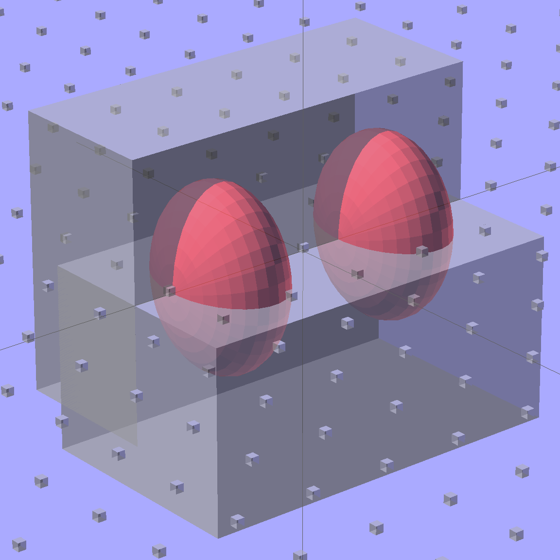
This view of the solid model shows the contact pins, with the lid floating over its alignment pegs (made from snippets of 1.75 mm filament):

The pegs simplify gluing the lid in place, a process for which you can never have enough clamps:

A cutaway shows the stepped holes around the contact pin, with the coil springs being the largest cylinder to the right of the solid-looking plug:

The contact pins look like this, at least after one remembers to slide on all the parts before soldering the wires in place:

I filed off the inevitable solder bumps, rounded the butt ends with gentle suasion, and generally tidied the pins up so they’re smooth and symmetrical. The springs don’t have a lot of oomph, so wasting any force on friction or binding is a Bad Thing.
The holes require reaming with twist drills for a nice slip fit around the pins. The OpenSCAD script prints out the relevant diameters and depths:
ECHO: "Contact pin tip dia: 1.6" ECHO: "Drill depth to taper end: 24.1 -- Dia: 2.4" ECHO: " to ferrule end: 15 -- Dia: 3.1" ECHO: " to plug end: 4 -- Dia: 5.2"
Grab the proper drill in a pin punch, adjust so that length protrudes, and have at it. Making the holes about 0.2 mm larger than nominal works well, although your mileage will definitely vary.
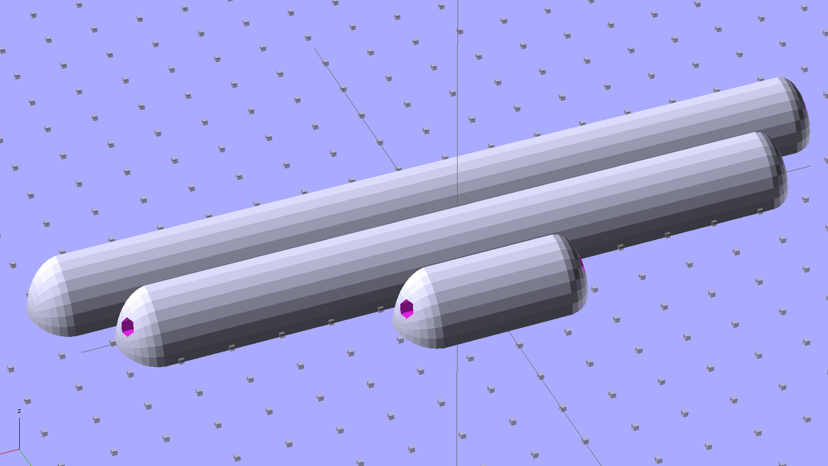
The build layout includes extra retaining plugs, as they tend to go walkabout under the bench:

Add a dab of PVC cement with THF inside the holes and the plugs push firmly into place:

I loves me my 3D printer…
The OpenSCAD source code:
// Holder for Canon NB-6L Li-Ion battery
// Ed Nisley KE4ZNU January 2013
include <MCAD/boxes.scad>
// Layout options
Layout = "Plugs"; // Show Build Fit Case Lid Pins Plugs AlignPins
//- Extrusion parameters - must match reality!
// Print with +2 shells and 3 solid layers
ThreadThick = 0.20;
ThreadWidth = 0.40;
HoleWindage = 0.2;
function IntegerMultiple(Size,Unit) = Unit * ceil(Size / Unit);
Protrusion = 0.1; // make holes end cleanly
inch = 25.4;
BuildOffset = 3.0; // clearance for build layout
Gap = 8.0; // separation for Fit parts
//- Battery dimensions - rationalized from several samples
// Coordinate origin at battery corner by contact plates on bottom surface
BatteryLength = 42.5;
BatteryWidth = 35.5;
BatteryThick = 7.0;
ContactWidth = 2.10;
ContactLength = 4.10;
ContactRecess = 0.85;
ContactOC = 3.18; // center-to-center across contact face
ContactOffset = 4.45; // offset from battery edge
ContactHeight = 3.05; // offset from battery bottom plane
AlignThick = 2.8; // alignment recesses on contact face
AlignDepth = 2.0; // into face
AlignWidth1 = 0.7; // across face at contacts
AlignWidth2 = 2.0; // ... other edge
//- Pin dimensions
PinTipDia = 1.6;
PinTipLength = 10.0;
PinTaperLength = 2.3;
PinShaftDia = 2.4;
PinShaftLength = 6.8;
PinFerruleDia = 3.1;
PinFerruleLength = 2.0;
PinLength = PinTipLength + PinTaperLength + PinShaftLength + PinFerruleLength;
ExtendRelax = 1.5 + ContactRecess; // pin extension when no battery is present
ExtendOvertravel = 1.0; // ... beyond engaged position
//- Spring dimensions
SpringDia = 3.1; // coil OD
SpringMax = 9.3;
SpringLength = SpringMax - 0.3; // slightly compressed
SpringMin = 4.5;
SpringPlugOD = IntegerMultiple(5.0,ThreadWidth); // plug retaining the spring
SpringPlugID = 2.0;
SpringPlugLength = IntegerMultiple(4.0,ThreadWidth);
SpringPlugSides = 3*4;
SpringTravel = ExtendRelax + ExtendOvertravel;
//- Holder dimensions
GuideRadius = ThreadWidth; // friction fit ridges
GuideOffset = 10;
WallThick = 4*ThreadWidth; // holder sidewalls
BaseThick = 6*ThreadThick; // bottom of holder to bottom of battery
TopThick = 6*ThreadThick; // top of battery to top of holder
ThumbRadius = 10.0; // thumb opening at end of battery
CornerRadius = 3*ThreadThick; // nice corner rounding
CaseLength = SpringPlugLength + SpringLength + PinLength - ExtendRelax
+ BatteryLength + GuideRadius + WallThick;
CaseWidth = 2*WallThick + 2*GuideRadius + BatteryWidth;
CaseThick = BaseThick + BatteryThick + TopThick;
AlignPinOD = 1.75; // lid alignment pins - filament snippets
AlignPinLength = 5.0;
AlignPinInset = 7.0;
//- XY origin at front left battery corner, Z on platform below that
CaseLengthOffset = -(SpringPlugLength + SpringLength + PinLength - ExtendRelax);
CaseWidthOffset = -(WallThick + GuideRadius);
CaseThickOffset = BaseThick;
LidLength = ExtendRelax - CaseLengthOffset;
echo(str("Contact pin tip dia: ",PinTipDia));
echo(str("Drill depth to taper end: ",
(SpringPlugLength + SpringLength + PinFerruleLength + PinShaftLength + PinTaperLength),
" -- Dia: ",PinShaftDia));
echo(str(" to ferrule end: ",
(SpringPlugLength + SpringLength + PinFerruleLength),
" -- Dia: ",PinFerruleDia));
echo(str(" to plug end: ",SpringPlugLength,
" -- Dia: ",SpringPlugOD));
//----------------------
// Useful routines
module PolyCyl(Dia,Height,ForceSides=0) { // based on nophead's polyholes
Sides = (ForceSides != 0) ? ForceSides : (ceil(Dia) + 2);
FixDia = Dia / cos(180/Sides);
cylinder(r=(FixDia + HoleWindage)/2,
h=Height,
$fn=Sides);
}
module ShowPegGrid(Space = 10.0,Size = 1.0) {
Range = floor(50 / Space);
for (x=[-Range:Range])
for (y=[-Range:Range])
translate([x*Space,y*Space,Size/2])
%cube(Size,center=true);
}
//-------------------
//-- Guides for tighter friction fit
module Guides() {
translate([GuideOffset,-GuideRadius,CaseThickOffset])
PolyCyl(2*GuideRadius,(BatteryThick - Protrusion),4);
translate([GuideOffset,(BatteryWidth + GuideRadius),CaseThickOffset])
PolyCyl(2*GuideRadius,(BatteryThick - Protrusion),4);
translate([(BatteryLength - GuideOffset),-GuideRadius,CaseThickOffset])
PolyCyl(2*GuideRadius,(BatteryThick - Protrusion),4);
translate([(BatteryLength - GuideOffset),(BatteryWidth + GuideRadius),CaseThickOffset])
PolyCyl(2*GuideRadius,(BatteryThick - Protrusion),4);
translate([(BatteryLength + GuideRadius),GuideOffset/2,CaseThickOffset])
PolyCyl(2*GuideRadius,(BatteryThick - Protrusion),4);
translate([(BatteryLength + GuideRadius),(BatteryWidth - GuideOffset/2),CaseThickOffset])
PolyCyl(2*GuideRadius,(BatteryThick - Protrusion),4);
}
//-- Contact pins (holes therefore)
module PinShape() {
union() {
cylinder(r=(PinTipDia + HoleWindage)/2,h=(PinTipLength + Protrusion),$fn=6);
translate([0,0,PinTipLength])
cylinder(r=(PinShaftDia + HoleWindage)/2,
h=(PinTaperLength + PinShaftLength + Protrusion),$fn=6);
translate([0,0,(PinLength - PinFerruleLength)])
cylinder(r=(PinFerruleDia + HoleWindage)/2,
h=(PinFerruleLength + Protrusion),$fn=6);
translate([0,0,(PinLength)])
cylinder(r=(SpringDia + HoleWindage)/2,
h=(SpringLength + Protrusion),$fn=6);
translate([0,0,(PinLength + SpringLength - HoleWindage)]) // windage for hole length
cylinder(r=(SpringPlugOD + HoleWindage)/2,h=3*SpringPlugLength,$fn=SpringPlugSides);
// translate([0,0,(PinLength + SpringLength + SpringPlugLength)])
// cylinder(r=(SpringPlugOD + HoleWindage)/2,h=2*SpringPlugLength,$fn=SpringPlugSides); // extend hole
}
}
module PinAssembly() {
translate([ExtendRelax,ContactOffset,CaseThickOffset + ContactHeight]) {
rotate([0,270,0]) {
PinShape(); // pins
translate([0,(2*ContactOC),0])
PinShape();
}
}
}
//-- Alignment pins
module AlignPins() {
for (x=[-1,1])
translate([x*(LidLength - 2*AlignPinInset)/2,0,0])
rotate(45)
PolyCyl(AlignPinOD,AlignPinLength);
}
//-- Case with origin at battery corner
module Case() {
difference() {
union() {
difference() {
translate([(CaseLength/2 + CaseLengthOffset),
(CaseWidth/2 + CaseWidthOffset),
(CaseThick/2)])
roundedBox([CaseLength,CaseWidth,CaseThick],CornerRadius); // basic case shape
translate([-ExtendOvertravel,-GuideRadius,CaseThickOffset])
cube([(BatteryLength + GuideRadius + ExtendOvertravel),
(BatteryWidth + 2* GuideRadius),
(BatteryThick + Protrusion)]); // battery space
}
Guides();
translate([-ExtendOvertravel,-GuideRadius,BaseThick])
cube([(AlignDepth + ExtendOvertravel),
(AlignWidth1 + GuideRadius),
AlignThick]); // alignment blocks
translate([-ExtendOvertravel,
(BatteryWidth - AlignWidth2),
BaseThick])
cube([(AlignDepth + ExtendOvertravel),
(AlignWidth2 + GuideRadius),
AlignThick]);
}
translate([(-ExtendOvertravel),
(CaseWidthOffset - Protrusion),
(CaseThickOffset + BatteryThick)])
cube([CaseLength,
(CaseWidth + 2*Protrusion),
(TopThick + Protrusion)]); // battery access
translate([(CaseLengthOffset - Protrusion),
(CaseWidthOffset - Protrusion),
(CaseThickOffset + BatteryThick)])
cube([(CaseLength + 2*Protrusion),
(CaseWidth + 2*Protrusion),
(TopThick + Protrusion)]); // battery insertion allowance
translate([(BatteryLength - Protrusion),
(CaseWidth/2 + CaseWidthOffset),
(CaseThickOffset + ThumbRadius)])
rotate([90,0,0])
rotate([0,90,0])
cylinder(r=ThumbRadius,
h=(WallThick + GuideRadius + 2*Protrusion),
$fn=22); // remove thumb notch
PinAssembly();
translate([-LidLength/2,BatteryWidth/2,CaseThick - TopThick - (AlignPinLength - TopThick/2)])
AlignPins();
}
}
module Lid() {
difference() {
translate([0,0,(CaseThick/2 - BaseThick - BatteryThick)])
roundedBox([LidLength,
CaseWidth,CaseThick],CornerRadius);
translate([0,0,-(CaseThick/2)])
cube([(LidLength + 2*Protrusion),
(CaseWidth + 2*Protrusion),
(CaseThick)],center=true);
translate([-ExtendRelax,0,-(AlignPinLength - TopThick/2)])
AlignPins();
}
}
module PlugShape() {
difference() {
cylinder(r=SpringPlugOD/2,h=SpringPlugLength,$fn=SpringPlugSides);
translate([0,0,-Protrusion])
PolyCyl(SpringPlugID,(SpringPlugLength + 2*Protrusion),SpringPlugSides);
}
}
module Plugs() {
translate([0,ContactOC,0])
PlugShape();
translate([0,-ContactOC,0])
PlugShape();
}
//-------------------
// Build it!
ShowPegGrid();
if (Layout == "Case")
Case();
if (Layout == "Lid")
Lid();
if (Layout == "Plugs")
for (i=[-1:1])
translate([i*1.5*SpringPlugOD,0,0])
Plugs();
if (Layout == "Pins")
PinShape();
if (Layout == "AlignPins")
AlignPins();
if (Layout == "Show") { // reveal pin assembly
difference() {
Case();
translate([(CaseLengthOffset - Protrusion),
(CaseWidthOffset - Protrusion + WallThick + ContactOffset + ContactOC),
(BaseThick + ContactHeight)])
cube([(-CaseLengthOffset + Protrusion),
(CaseWidth + 2*Protrusion),
CaseThick + BaseThick - ContactHeight + Protrusion]);
translate([(CaseLengthOffset - Protrusion),
(CaseWidthOffset - Protrusion),
-Protrusion])
cube([(-CaseLengthOffset + Protrusion),
(WallThick + GuideRadius + ContactOffset + Protrusion),
CaseThick]);
}
translate([ExtendRelax,ContactOffset,(CaseThickOffset + ContactHeight)]) { // pins
rotate([0,270,0]) {
%PinShape();
// translate([0,(2*ContactOC),0])
// %PinShape();
}
}
translate([CaseLengthOffset,ContactOffset,(CaseThickOffset + ContactHeight)])
rotate([0,90,0])
PlugShape();
}
if (Layout == "Build") {
translate([-(CaseLength/2 + CaseLengthOffset),-(CaseWidthOffset - BuildOffset),0])
Case();
translate([CaseWidth/2,(CaseLengthOffset/2 - BuildOffset),0])
rotate([0,0,90])
Lid();
for (i=[-1:1])
translate([CaseLengthOffset/2 + i*1.5*SpringPlugOD,-CaseWidth/2,0])
Plugs();
}
if (Layout == "Fit") {
Case();
translate([(-LidLength/2 + ExtendRelax),
(CaseWidth/2 + CaseWidthOffset),
(BaseThick + BatteryThick + Gap)])
Lid();
translate([ExtendRelax,ContactOffset,CaseThickOffset + ContactHeight]) { // pins
rotate([0,270,0]) {
%PinShape();
translate([0,(2*ContactOC),0])
%PinShape();
}
}
translate([CaseLengthOffset,
(ContactOffset + ContactOC),
(CaseThickOffset + ContactHeight)])
rotate([0,90,0])
Plugs();
translate([-LidLength/2,BatteryWidth/2,CaseThick])
# AlignPins();
}
Our Larval Engineer reported that her camera, which is my old Casio pocket camera, has begun fading away, so we’re getting her a shiny new camera of her very own. Being a doting father, I picked up a pair of Wasabi NB-6L batteries (and a charger, it not costing much more for the package) so she’s never without electrons, and did the usual rundown test on all three batteries:

Fairly obviously, the Wasabi batteries aren’t first tier products, but they’re definitely better than that bottom-dollar crap from eBay.
A few months ago I fired the Thing-O-Matic, only to have it wake up dead. Not exactly dead, but spitting out checksum errors on simple G-Code files sent from Pronterface, which used to work just fine. Trying a bit of this-and-that to no avail, I proposed to The Mighty Thor that I could loan the carcass to Squidwrench, reanimate it with a less bizarre set of hardware and firmware than the much-hacked Makerbot menagerie under the hood, and use it as an exemplar in my 3D Printing classes.
Fortunately, that particular Thing-O-Matic has the most well-documented hardware evah…
Matt suggested an Azteeg X3 controller, because it has thermocouple inputs that match the existing sensor, Thor ordered one, and I tinkered up a first-pass version of Marlin that could read the inputs and twiddle the motors. The firmware is on Github, not that you’ll need it for anything you’re doing; more on that later.
Here’s the Official Doc for the microstepping jumpers hidden under the driver boards:

That’s XYZE = 16 16 8 4, respectively, with a spare slot (and spare driver, not installed) for the second extruder it’ll never have.
A first pass at setting the motor currents
The extruder’s Type K thermocouple connects to the TC1 port on the shield, exactly reversed from the way you see the test thermocouple there: the red lead is to the left, the yellow lead is to the right. If you get it backwards, the indicated temperature goes down when you touch the bead. The printer’s thermocouple has some backstory.
The 10 kΩ thermistor bead connects to the BED port on the main board and isn’t polarized. The Heated Build Platform has a bit of backstory, too.
The gutted TOM286 carcass with the MBI hardware off to the side:

After a few sessions, it looked pretty cheerful again:

The penguin duct tape adds a festive flair, don’t you agree?
This is what you see when looking down through the acrylic baseplate:

The blurry silver rectangle off to the left is an aluminum channel glommed to bottom of the acrylic baseplate with silicone snot to eliminate a nasty mechanical resonance.
The thermal cutout circuitry isn’t wired in yet; the ATX power supply has its -Power-On pin hotwired to the adjacent ground pin for now. The X3 gets its power directly from the +12 V supply, so there doesn’t seem to be any way to power the X3 from the +5 V Standby ouput, deliver +12 V to the motors, and switch the supply through the X3’s ATX output pin.
The heaters work fine, the motors turn properly, and the extruder feeds molten plastic; all the motor calibrations seem to be pretty close. The first test object was a total botch, of course, but the printer’s parts seem to work OK again.
Next step: calibration!