Ed Nisley's Blog: Shop notes, electronics, firmware, machinery, 3D printing, laser cuttery, and curiosities. Contents: 100% human thinking, 0% AI slop.
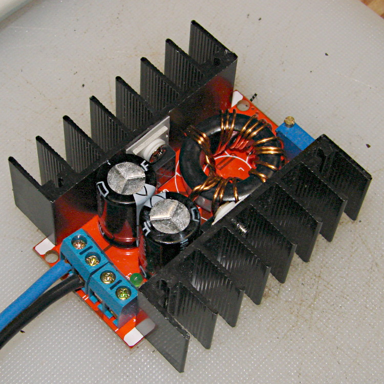
For reasons that will become apparent in a while, I got a pair (*) of boost power supplies from the usual eBay source, allegedly capable of boosting a 10-to-32 VDC input to a 12-to-35 VDC output, up to 10 A and 150 W:
Boost power supply
After establishing that it would not produce 30 V into a 5.9 Ω load (5.1 A, but 152 W), I got systematic.
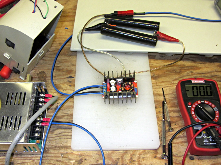
A 100 Ω resistor drew 1/4 A while I set the output to 28 V. Doubling up the resistors showed that it worked OK at half an amp:
Boost supply – 50 ohm load
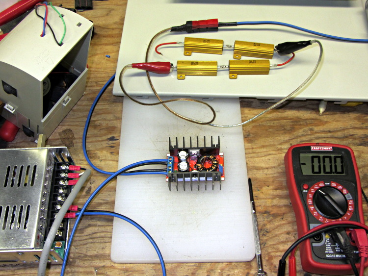
Four 6 Ω resistors in series draw 1.2 A, then (channeling the true spirit of DIY 3D printing) two in series drew 2.3 A:
Boost supply – 12 ohm load
That’s 32 W each and, yes, they did get toasty, but, no, I didn’t leave them turned on all that long.
But a 6 Ω resistance still didn’t work, so the supply can’t provide 4.7 A at 130 W. In case you were wondering, that’s two 6 Ω resistors in series and a pair of those strings in parallel, so each resistor still sees 32 W.
In terms of driving the actual load, these supplies aren’t going to light it up.
Ah, well, whaddaya want for five buck from halfway around the planet?
(*) Davy’s Aphorism: Never buy only one of any surplus item, because you’ll never find another. Get at least two, maybe three if it’s something you might actually use.
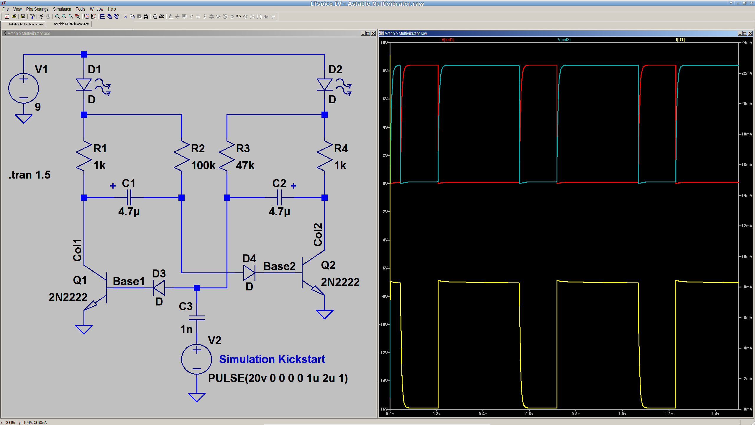
We’ve been kicking around ideas for introductory soldering / electronics projects at Squidwrench, which prompted me to come up with a classic astable multivibrator circuit:
Astable Multivibrator – simulation
Everything is totally non-critical: it should oscillate as long as the base resistors are small enough to lightly saturate the transistors. The LEDs let you know it’s actually working.
You’d probably want a few decades of caps and a decade’s worth of resistors on pin headers, so as to cover the range from visible blinkiness to nasty audio squeal.
The pulse generator and cap at the bottom apply a jolt at T=0 to knock the circuit off balance. Otherwise, the simulation will just sit there and do nothing; in the real world, of course, nothing stays balanced for very long.
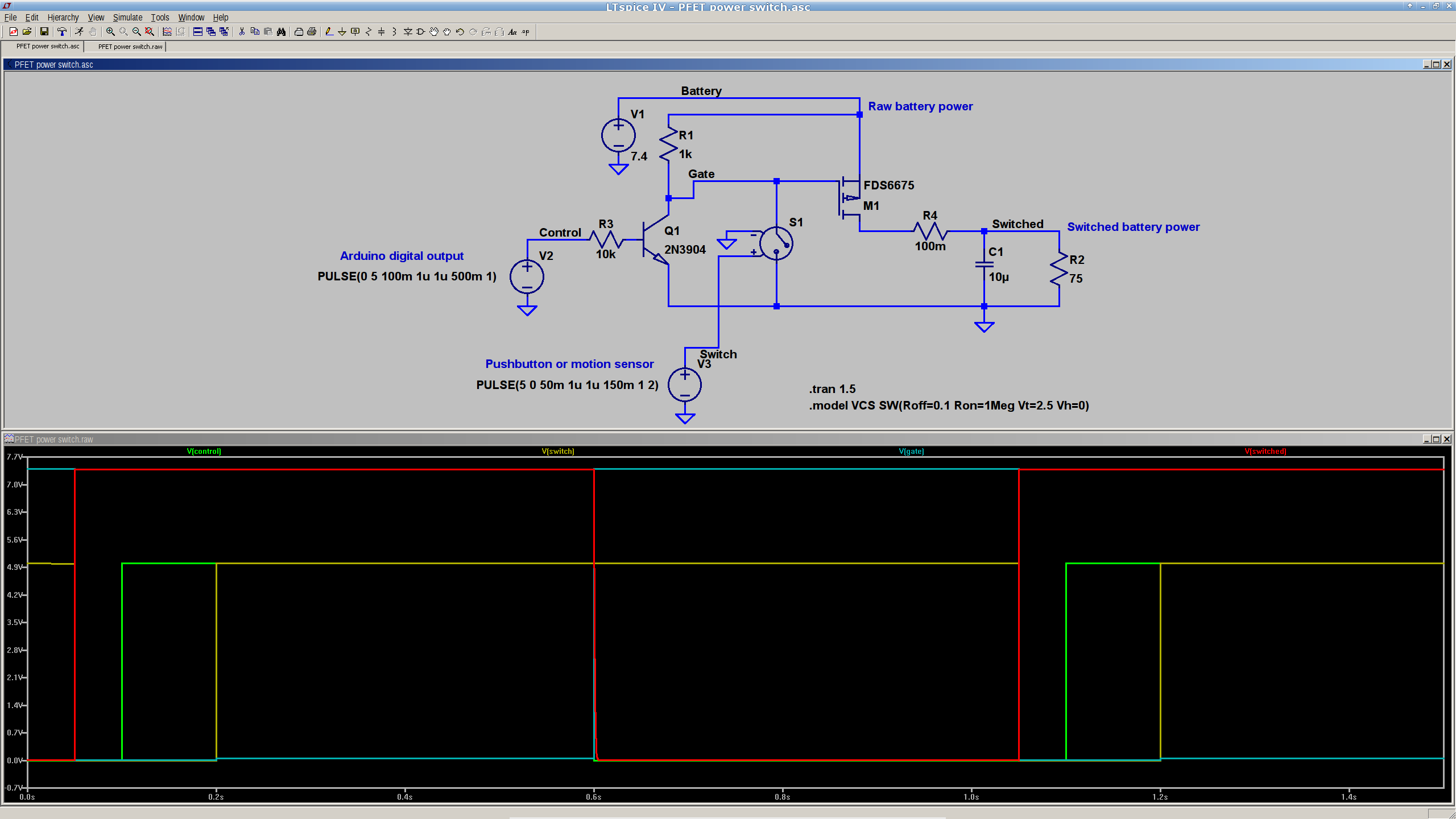
This is a simulation showing that a p-channel power MOSFET should work fine as a battery cutoff / switch for the bike taillight (clicky for many more dots):
P-MOSFET power switch
The general idea is to have a pushbutton or vibration sensor turn on the power, whereupon the Arduino wakes up and activates an output pin that holds the power on. When it’s time to shut down, the Arduino turns that output pin off, the power goes away, and everybody’s happy.
The MOSFET must be not only p-channel, but also have a logic-level gate, which is a rare and precious combination among cheap surplus MOSFETs. I’m hoping those FDS6675 MOSFETs work better than their package looks.
The capacitor and resistor over on the right simulate a reasonable load.
The voltage-controlled switch in the middle represents the vibration sensor, which is either shorted or open as determined by the voltage source at the bottom. There doesn’t seem to be any other Spice-ish way to do that.
The Arduino output, simulated by another voltage source drives the NPN transistor, which isolates the output pin from the 7.4 V (up to maybe 8.5 V when fully charged) Li-ion battery. It also isolates it from the switch, which would otherwise yank the output pin to ground if you pushed the button when the power was already on.
You’d want a few more pullup and pulldown resistors to ensure things stay where they’re put while the lights are out. I’d want to measure an actual vibration sensor; it may require a pulse stretcher to ensure the Arduino has enough time to wake up and smell the electrons.
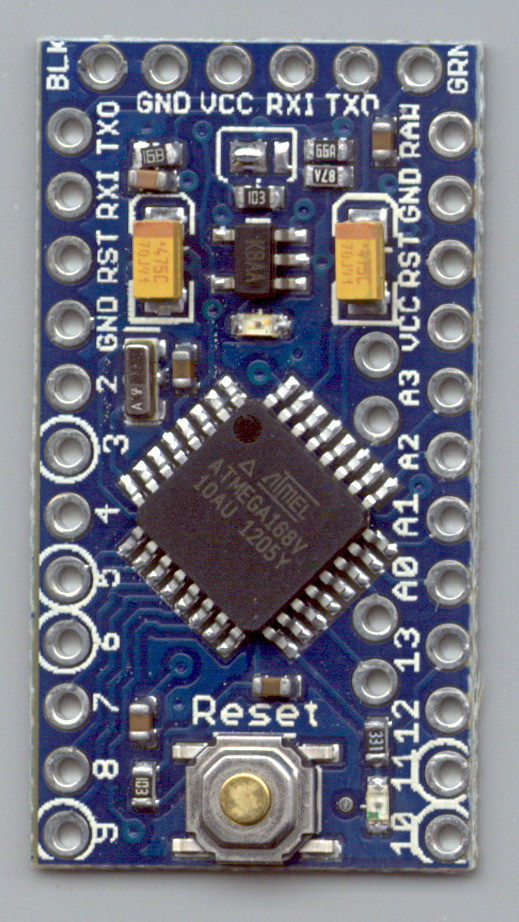
Measured from the Official PCB Layout, with the board origin at the lower-left corner of the PCB, down there by the D9 pin, in mils (0.001 inch):
D9 = (50,50)
D10 = (650,50)
A5 = (535,805)
A4 = (535,705)
A7 = (535,393)
A6 = (535,293)
FTDI header = (100,1250) to (600,1250)
Reset button = (350,105)
D13 LED = (540,100)
PWR LED = (350,850)
Upper fiducial = (160,1140)
Lower fiducial = (490,100)
Subtract 50 mils from each of those coordinates to put the origin at the middle of the D9 pin, which may be more useful. Doing that in inches produces:
D9 = (0.000,0.000)
D10 = (0.600,0.000)
A5 = (0.485,0.755)
A4 = (0.485,0.655)
A7 = (0.485,0.343)
A6 = (0.485,0.243)
FTDI header = (0.050,1.200) to (0.550,1.200)
Reset button = (0.300,0.055)
D13 LED = (0.490,0.050)
PWR LED = (0.300,0.800)
Upper fiducial = (0.110,1.090)
Lower fiducial = (0.440,0.050)
Trust, but verify…
Yes, this is a knockoff PCB from the usual eBay vendor, not from Sparkfun. Contents may settle during shipment. Enlarged to show texture. Your mileage may vary. No warranty, either express or implied, no lie. Do not eat.
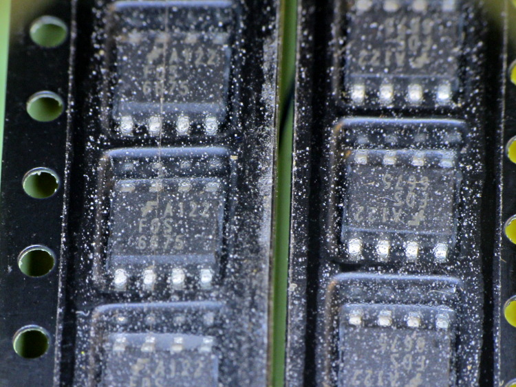
So I picked up a lot of 20 p-channel MOSFETs from the usual eBay supplier in China, which arrived in good order. As is often the case, the SOIC chips are in snippets of tape-and-reel carrier, but this tape looked decidedly odd:
eBay FDS6675 Tape Cover Contamination
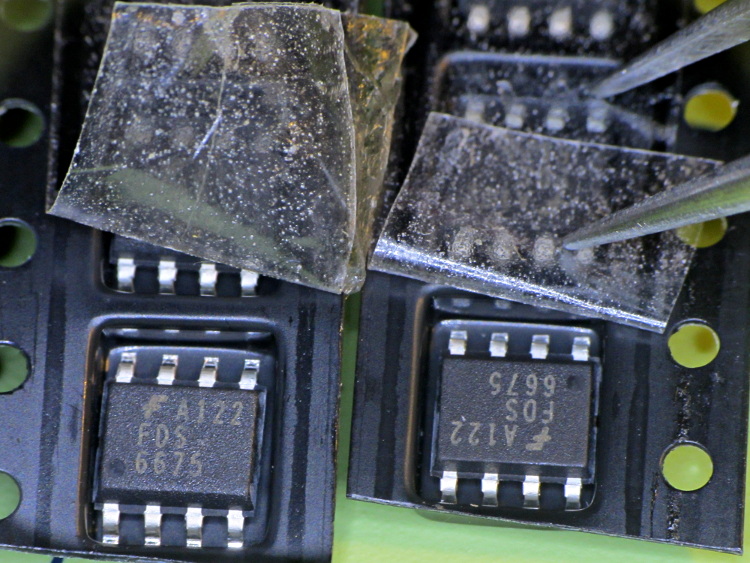
Peeling back the tape shows that the crud is just on (or perhaps inside) the tape, not on the ICs or inside the carrier pockets:
Some of those specks are dirt, some seem to be bubbles, other are just, well, I don’t know what they might be. Maybe they were having a bad day in the tape factory?
One might reasonably conclude the chips aren’t in their original carrier…
I must gimmick up a quick test to verify that the chips behave like p-channel MOSFETs, instead of, oh, solid plastic; that Fairchild logo looks a bit grotty, doesn’t it?
With that hardware in hand, a dab of firmware produces this result:
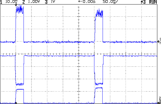
Hall Current Sense – 120 mA 25 ms 250 ms
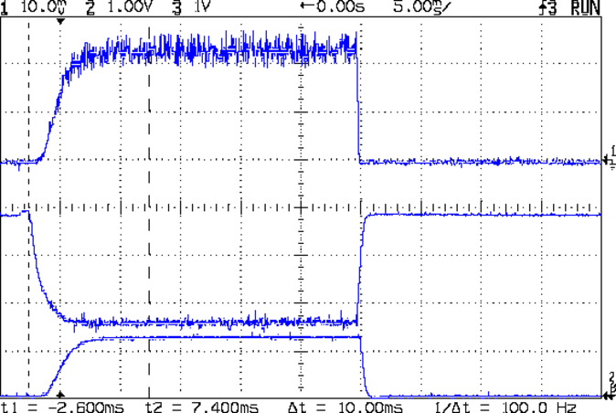
A detailed look at one pulse:
Hall Current Sense – 120 mA 25 ms 250 ms – detail
The top trace is the total LED current, nominally 120 mA, at 50 mA/div. The ripple (which is a nice triangle waveform at a faster sweep) comes from the 32 kHz PWM pulse train, despite passing through a 1 ms RC filter; the MOSFET runs in the linear region and makes a great amplifier.
The middle trace is the MOSFET drain voltage at 1 V/div. The on-state voltage runs around 1.6 V, so the LEDs see about 5.9 V at 120 mA, about what you’d expect, with the little bit of PWM ripple accounting for the current sawtooth in the top trace. The off-state voltage is only 3.8 V, because the LEDs soak up the rest; it’s about 1.2 V per LED.
The bottom trace is the current-sense amp output. The 1 nF cap in the op amp feedback loop rolls it off at 600 Hz, so there’s not much ripple at all in there. That goes directly to the Arduino’s ADC, where it’s further averaged over 10 samples.The LEDs take a couple of milliseconds to get up to full intensity, but it’s much faster than an incandescent filament: this thing blinks rather than flashes.
The current in each LED string runs from about 15 mA to 25 mA, with all the “old” LEDs at the low end and the “new” LED strings at the high end. Using unsorted LEDs from the same batch will probably be OK, although I’ll measure them just to see what they’re like.
The LEDs dissipate 700 mW and the MOSFET wastes 192 mW, so the efficiency is around 79%. Not too shabby for a linear regulator and it only gets better as the battery discharges. The toroid winding burns maybe 300 μW, so it’s not in the running; to be fair, a 1 Ω sense resistor would account for only 14 mW, but it would drop 120 mV instead of 3 mV, which is what matters more when the battery voltage drops.
That’s during the pulse, which should have a duty cycle under 25% or so, which means 175 mW and 48 mW on the average. Obviously, no heatsinks needed: each LED runs at 7 mW average under those conditions.
The firmware steps the gate voltage by the smallest possible increment, about 20 mV = 5 V / 256. The feedback loop adjusts the gate voltage in single steps to avoid goosing the LEDs with too much current; a binary search wouldn’t work very well at all. I think it’d be a good idea to build a table of transconductance (gate voltage to LED current) by ramping the gate voltage during startup, then fine-tune the coefficients during each pulse.
The console log tells the tale:
Hall effect Current Regulator
Ed Nisley - KE4ZNU - August 2013
Given Vcc: 5010 mV
Given VBatt divider ratio: 0.500
Bandgap reference voltage: 1105 mV
Battery voltage: 7551 mV
Nulling Hall sensor offset: 0 PWM
Final Hall sensor offset: 209 PWM
Gate voltage: 1947 mV  LED Current: 5 mA
Gate voltage: 1966 mV  LED Current: 6 mA
Gate voltage: 1986 mV  LED Current: 6 mA
Gate voltage: 2005 mV  LED Current: 7 mA
Gate voltage: 2025 mV  LED Current: 8 mA
Gate voltage: 2040 mV  LED Current: 8 mA
Gate voltage: 2064 mV  LED Current: 10 mA
Gate voltage: 2084 mV  LED Current: 11 mA
Gate voltage: 2103 mV  LED Current: 13 mA
Gate voltage: 2123 mV  LED Current: 14 mA
Gate voltage: 2142 mV  LED Current: 17 mA
Gate voltage: 2162 mV  LED Current: 19 mA
Gate voltage: 2177 mV  LED Current: 22 mA
Gate voltage: 2201 mV  LED Current: 25 mA
Gate voltage: 2221 mV  LED Current: 29 mA
Gate voltage: 2240 mV  LED Current: 33 mA
Gate voltage: 2255 mV  LED Current: 38 mA
Gate voltage: 2275 mV  LED Current: 44 mA
Gate voltage: 2294 mV  LED Current: 49 mA
Gate voltage: 2314 mV  LED Current: 56 mA
Gate voltage: 2333 mV  LED Current: 63 mA
Gate voltage: 2353 mV  LED Current: 70 mA
Gate voltage: 2372 mV  LED Current: 79 mA
Gate voltage: 2392 mV  LED Current: 89 mA
Gate voltage: 2412 mV  LED Current: 99 mA
Gate voltage: 2431 mV  LED Current: 110 mA
Gate voltage: 2451 mV  LED Current: 122 mA
Gate voltage: 2431 mV  LED Current: 110 mA
Gate voltage: 2451 mV  LED Current: 121 mA
Gate voltage: 2431 mV  LED Current: 110 mA
Gate voltage: 2451 mV  LED Current: 122 mA
Gate voltage: 2431 mV  LED Current: 110 mA
Gate voltage: 2451 mV  LED Current: 121 mA
The current feedback tweaks the gate voltage by one PWM increment on each loop, so the LED current pulses alternate between 110 and 122 mA when the loop finally reaches the setpoint. This doesn’t make any practical difference, as each LED string’s current varies by a few mA, at most, but maybe there should be a deadband of a bit more than ±1/2 PWM increment around the actual current.
The Arduino source code:
// LED Curve Tracer
// Ed Nisley - KE4ANU - August 2013

#include <stdio.h>

//----------
// Pin assignments

const byte PIN_READ_VBATT = 0;		// AI - battery voltage from divider
const byte PIN_READ_CURRENT = 1;	// AI - current sense amp
const byte PIN_READ_VGATE = 2;		// AI - actual gate voltage
const byte PIN_READ_HALL = 3;		// AI - raw Hall sensor voltage

const byte PIN_SET_BIAS = 11;		// PWM - VCC/2 bias voltage
const byte PIN_SET_VGATE = 3;		// PWM - MOSFET gate voltage

const byte PIN_HEARTBEAT = 13;		// DO - Arduino LED
const byte PIN_SYNC = 2;			// DO - scope sync output

//----------
// Constants

const float MaxLEDCurrent = 0.120;		// maximum LED current

const float Vcc = 5.01; 				// Arduino supply -- must be measured!

const float VBattRatio = 3.03/6.05;		// measured division ratio for battery divider

const float VStep = Vcc/256;			// minimum PWM voltage increment = 5 V / 256

const float IGain = 0.100;				// Hall sense voltage to LED current

const byte PWM_Settle = 10;				// PWM settling time ms

// Timer prescaler = 1:1 for 32 kHz PWM
#define TCCRxB 0x01

#define MK_UL(fl,sc) ((unsigned long)((fl)*(sc)))
#define MK_U(fl,sc) ((unsigned int)((fl)*(sc)))
#define MK_I(fl,sc) ((int)((fl)*(sc)))

//----------
// Globals

float AVRef1V1;					// 1.1 V bandgap reference - calculated from Vcc

float VBatt;					// battery voltage - calculated from divider
float VGateSense;				// actual gate voltage - measured after PWM filter
float ILEDSense;				// LED current from Hall effect sensor

float VGateDrive;				// gate drive voltage

byte PWMHallOffset;				// zero-field Hall effect sensor bias

long unsigned long MillisNow, MillisThen;	// sampled millis() value

//-- Read AI channel
//      averages several readings to improve noise performance
//		returns value in volts assuming known VCC ref voltage

#define NUM_T_SAMPLES    10

float ReadAI(byte PinNum) {

  word RawAverage;

  digitalWrite(PIN_SYNC,HIGH);					// scope sync

  RawAverage = (word)analogRead(PinNum);		// prime the averaging pump

  for (int i=2; i <= NUM_T_SAMPLES; i++) {
    RawAverage += (word)analogRead(PinNum);
  }

  digitalWrite(PIN_SYNC,LOW);

  RawAverage /= NUM_T_SAMPLES;

  return Vcc * (float)RawAverage / 1024.0;

}

//-- Set PWM output

void SetPWMVoltage(byte PinNum,float PWMVolt) {

byte PWM;

  PWM = constrain((byte)(255.0 * PWMVolt / Vcc),0,255);

  analogWrite(PinNum,PWM);
  delay(PWM_Settle);

}

//-- compute actual 1.1 V bandgap reference based on known VCC = AVcc (more or less)
//		adapted from http://code.google.com/p/tinkerit/wiki/SecretVoltmeter

float ReadBandGap(void) {

  word ADCBits;
  float VBandGap;

  ADMUX = _BV(REFS0) | _BV(MUX3) | _BV(MUX2) | _BV(MUX1);	// select 1.1 V input
  delay(2); // Wait for Vref to settle

  ADCSRA |= _BV(ADSC);										// Convert
  while (bit_is_set(ADCSRA,ADSC));

  ADCBits = ADCL;
  ADCBits |= ADCH<<8;

  VBandGap = Vcc * (float)ADCBits / 1024.0;
  return VBandGap;
}

//-- Helper routine for printf()

int s_putc(char c, FILE *t) {
  Serial.write(c);
}

//------------------
// Set things up

void setup() {

float AVRef1V1;

  pinMode(PIN_HEARTBEAT,OUTPUT);
  digitalWrite(PIN_HEARTBEAT,LOW);	// show we arrived

  pinMode(PIN_SYNC,OUTPUT);
  digitalWrite(PIN_SYNC,LOW);		// show we arrived

  TCCR1B = TCCRxB;					// set frequency for PWM 9 & 10
  TCCR2B = TCCRxB;					// set frequency for PWM 3 & 11

  analogWrite(PIN_SET_VGATE,0);		// force gate voltage = 0

  Serial.begin(57600);
  fdevopen(&s_putc,0);				// set up serial output for printf()

  printf("Hall effect Current Regulator\r\nEd Nisley - KE4ZNU - August 2013\r\n");

  printf("Given Vcc: %d mV\r\n",MK_I(Vcc,1000.0));
  printf("Given VBatt divider ratio: 0.%d\r\n",MK_I(VBattRatio,1000.0));

  AVRef1V1 = ReadBandGap();			// compute actual bandgap reference voltage
  printf("Bandgap reference voltage: %d mV\r\n",MK_I(AVRef1V1,1000.0));

  VBatt = ReadAI(PIN_READ_VBATT) / VBattRatio;
  printf("Battery voltage: %d mV\r\n",MK_I(VBatt,1000.0));

  SetPWMVoltage(PIN_SET_VGATE,0.0);		// zero LED current
  PWMHallOffset = 0;
  analogWrite(PIN_SET_BIAS,PWMHallOffset);
  printf("Nulling Hall sensor offset: %d PWM\r\n",PWMHallOffset);

  do {
	ILEDSense = IGain * ReadAI(PIN_READ_CURRENT);
//	printf("Current Sense: %d mA - ",MK_I(ILEDSense,1000.0));
	if (ILEDSense > 0.005) {
		PWMHallOffset += 1;
		analogWrite(PIN_SET_BIAS,PWMHallOffset);
        delay(PWM_Settle);
//		printf("Step offset: %d PWM\r\n",PWMHallOffset);
	}
  } while (ILEDSense > 0.005);
  printf("Final Hall sensor offset: %d PWM\r\n",PWMHallOffset);

  VGateDrive = 2.0;					// reasonable starting point

  MillisThen = millis();
}

//------------------
// Run the test loop

void loop() {

	if ((millis() - MillisThen) > 250) {
		MillisThen = millis();

		if (ILEDSense < MaxLEDCurrent) {
			VGateDrive += VStep;
		}
		else if (ILEDSense > MaxLEDCurrent) {
			VGateDrive -= VStep;
		}

		SetPWMVoltage(PIN_SET_VGATE,VGateDrive);

		VGateSense = ReadAI(PIN_READ_VGATE);
		printf("Gate voltage: %d mV  ",MK_I(VGateSense,1000.0));

		ILEDSense = IGain * ReadAI(PIN_READ_CURRENT);
		printf("LED Current: %d mA\r\n",MK_I(ILEDSense,1000.0));

		delay(50 - PWM_Settle - 3);
		SetPWMVoltage(PIN_SET_VGATE,0.0);

		digitalWrite(PIN_HEARTBEAT,!digitalRead(PIN_HEARTBEAT));
		digitalWrite(PIN_HEARTBEAT,!digitalRead(PIN_HEARTBEAT));
	}
}
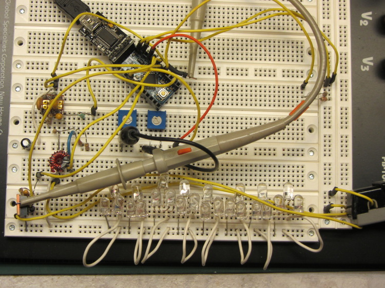
This hideous proof-of-concept lashup gathers a bunch of stuff I’ve been investigating into what’s definitely in the running for the most over-the-top LED blinky light ever:
Hall Effect LED Current Control – breadboard overview
The general idea:
A large-area bike taillight (tiny, narrow-beam, intense LEDs aren’t visible at a distance or off-axis)
Arduino Love closing the feedback loop (for programmatic blinkiness)
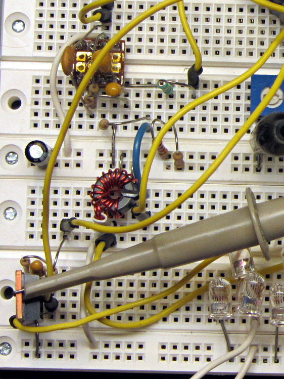
A closer look at the key analog parts:
Hall Effect LED Current Control – breadboard detail
The ferrite toroid near the middle surrounds that same “49E” Hall effect sensor. The ZVNL14 logic-level MOSFET in the lower right runs with about 2.4 V on the gate to put 120 mA through the LEDs. The cluster of parts just above it are the RC low-pass PWM filter, with the PWM running at 32 kHz. The snippet of perfboard near the top adapts a MAX4330 op amp to DIP pins. I used the twiddlepots to bring up the op amp and MOSFET circuitry by force-feeding bias and gate voltages.
The Arduino Pro Mini closes the feedback loop from current sensor to MOSFET gate. A knockoff Arduino Pro Mini is a $5 component, in onesies, delivered halfway around the planet. For low-volume stuff like this, you just build it right in and move on; there’s no reason to lay out a PCB with an ATmega328 chip and a handful of other parts. Unless you’re worried about power consumptions, as described below.
The schematic:
Hall Effect Current Feedback LED Driver – prototype schematic
The MAX4330 removes the Hall effect sensor’s VCC/2 bias, but it turns out the offset varies by enough from part to part and over temperature that a single twiddlepot setting won’t suffice. The RC filter near the middle of the schematic converts an Arduino PWM output into a voltage between 2.0 and 3.0 V, which puts more PWM resolution where it matters; the default 0.4% PWM steps are just too coarse. I think 16 bit PWM resolution would be A Very Good Thing here.
The first-pass program nulls the offset once, during the startup routine, but nulling whenever the LEDs turn off would be a Good Idea. The offset steps are 8 mV, about what you’d expect from 2/5 of the nominal 20 mV PWM increments. It ramps the offset up from zero, but you’d probably want to use a binary search.
The op amp has a voltage gain of about 28 that scales the toroid-plus-Hall-sensor output so that 500 mA in the winding produces 5 V. That gain isn’t quite high enough for the 120 mA I’m using for this collection of LEDs , but it makes the coefficient a nice round 0.10. It’d be good to have a calibrated current load, something around 100 mA, that would allow auto-calibration.
A 50% voltage divider lets the Arduino measure the nominal 7.4 V battery voltage and decide when to lower the current or change the blink pattern or kvetch about imminent blackout or something. Knowing both the battery voltage and the resistance of the current calibration load would let the program calculate the actual current for calibration. Given two calibration loads, then you could derive both the gain and the remaining offset; that’s likely too much trouble.
The Pro Mini board has a voltage regulator that provides +5 V for everything else in the circuit, which means putting the microcontroller into sleep mode won’t save any battery power. I think a p-channel MOSFET switch and a suicide output from the Arduino will be in order. A vibration sensor would give you auto power on and off, which would be a nice touch; MEMS sensors seem to want 3.3-ish V for supply and logic.
The entire lashup runs at about 60 mA with the LEDs turned off, which is way too high and may include some breadboard screwups; considerable reduction will be in order before this circuit makes any sense. The Hall effect sensor costs about 4 mA all by itself, plus another milliamp in the load resistor. The microcontroller should be around 10 – 20 mA, but the datasheet makes some assumptions that aren’t true for the Arduino runtime.
The program brute-forces the pulse timing, just to get this thing working. The main loop stalls while the LEDs are on, which is obviously a Bad Thing. The ADC conversions do some averaging, but I’m not confident it works well enough. The PWM output routine includes an entirely empirical delay to cover the filter time constants.
The blink pattern should be in a table. Given linear current control, you can have variable brightness; a “night taillight” mode that isn’t so shatteringly bright would be a Good Idea. The table might contain gate voltages for each current level, updated during the last pulse, so that the output would be Pretty Close at the beginning; you’d measure those values during startup.
A button or two for mode selection might be in order. Sealing buttons is always a problem, but this thing might not be totally waterproof anyway.