The Smell of Molten Projects in the Morning

Ed Nisley's Blog: Shop notes, electronics, firmware, machinery, 3D printing, laser cuttery, and curiosities. Contents: 100% human thinking, 0% AI slop.

Category: Electronics Workbench

Electrical & Electronic gadgets

  • HP Scope Probe Flange Repair

    Quite some time ago I manage to break the finger flange on one of my scope probes and, what with it being made of an un-glueable engineering plastic, a simple repair job failed quickly. It’s entirely round and a perfect lathe project, but … this is easier:

    HP Scope Probe Flange Repair
    HP Scope Probe Flange Repair

    You can see remnants of that failed repair just below the fracture:

    HP scope probe flanges - repair disk
    HP scope probe flanges – repair disk

    Some epoxy around the rim of the flange, plus filling the missing sector, looks about as grubby as you’d expect:

    HP Scope Probes - rear
    HP Scope Probes – rear

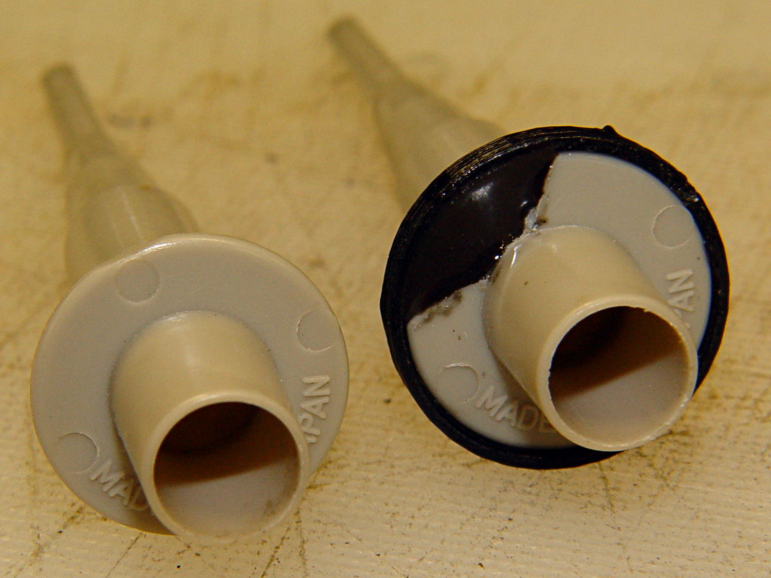
    That’s a tiny zit at about 1 o’clock which came off with fingernail pressure.

    From the business end, it actually looks pretty snappy:

    HP Scope Probes - front
    HP Scope Probes – front

    I’m mildly tempted to preemptively reinforce the other probes…

    The OpenSCAD source code joins two parts with coincident faces, but it worked out OK for once:

    // Tek Scope Probe Flange
    // Ed Nisley KE4ZNU November 2013
    
    //- Extrusion parameters must match reality!
    //  Print with 2 shells and 3 solid layers
    
    ThreadThick = 0.25;
    ThreadWidth = 0.40;
    
    HoleWindage = 0.2;
    
    Protrusion = 0.1;			// make holes end cleanly
    
    function IntegerMultiple(Size,Unit) = Unit * ceil(Size / Unit);
    
    //----------------------
    // Dimensions
    
    FlangeOD = 16.0;
    FlangeID = 8.75;
    FlangeThick = IntegerMultiple(1.25,ThreadThick);
    
    DiskOD = FlangeOD + 4*ThreadWidth;
    DiskThick = FlangeThick + 4*ThreadThick;
    
    NumSides = 8*4;
    
    //----------------------
    // Useful routines
    
    module PolyCyl(Dia,Height,ForceSides=0) {			// based on nophead's polyholes
    
      Sides = (ForceSides != 0) ? ForceSides : (ceil(Dia) + 2);
    
      FixDia = Dia / cos(180/Sides);
    
      cylinder(r=(FixDia + HoleWindage)/2,
               h=Height,
    	   $fn=Sides);
    }
    
    module ShowPegGrid(Space = 10.0,Size = 1.0) {
    
      Range = floor(50 / Space);
    
    	for (x=[-Range:Range])
    	  for (y=[-Range:Range])
    		translate([x*Space,y*Space,Size/2])
    		  %cube(Size,center=true);
    
    }
    
    //----------------------
    // Build it
    
    ShowPegGrid();
    
    	difference() {
    		union() {
    			translate([0,0,2*ThreadThick])
    				cylinder(r=DiskOD/2,h=DiskThick,$fn=NumSides);			// main repair part
    			cylinder(r1=(DiskOD - 2*ThreadWidth)/2,r2=DiskOD/2,h=2*ThreadThick,$fn=NumSides);
    		}
    		translate([0,0,(DiskThick - FlangeThick)])				// flange clearance
    			PolyCyl(FlangeOD,2*FlangeThick,NumSides);
    		translate([0,0,-DiskThick/2])
    			PolyCyl(FlangeID,2*DiskThick,NumSides);
    	}
    
  • Arduino Pro Mini Knockoff: Solder FAIL

    Although it’s not obvious, the two blue 2431 Ω resistors just above the toroid are a divider that scales the switched battery voltage (from the p-MOSFET on their left) by 50% and sends it to input A0 on the Arduino Pro Mini board:

    Hall effect sensor - toroid CCW field
    Hall effect sensor – toroid CCW field

    The firmware can use that input to dim the LEDs when the voltage drops below some preset threshold and, eventually, turn them off completely.

    Figuring the actual battery voltage is straightforward:

    • get 10 bit ADC value with analogRead()
    • multiply by actual VCC (measured at 4.96 V for this board)
    • divide by actual voltage divider ratio (measured at 3.78/7.57)

    Which, of course, reported the battery voltage was 4.116 V. Huh?

    After spending far too much time poking the code with a sharp stick, I wired the divider to the (previously unused) A6 and A7 inputs and dumped the raw ADC counts for all three. The answer should be somewhere near 763, but the three values came out around 215, 667, and 750. Huh?

    The A0 value is totally bogus, so I finally looked at the Arduino Pro Mini board:

    Arduino Pro Mini clone - chip overview
    Arduino Pro Mini clone – chip overview

    Hmmm. It turns out A0 is the second pin back on the left side:

    Arduino Pro Mini clone - unsoldered leads
    Arduino Pro Mini clone – unsoldered leads

    Double hmmm. An even closer look:

    Arduino Pro Mini clone - unsoldered A0 lead
    Arduino Pro Mini clone – unsoldered A0 lead

    Well, that was obvious after I figured out where to look

    I slathered flux on all the pins, touched each one with a soldering iron, and it’s all good.

    This is a knockoff Arduino Pro Mini board from eBay, of course, and the rest of the boards in that lot were OK. Their QC inspection almost certainly boils down to running the Blink sketch: if the LED blinks after the power goes on, ship it!

    Blink doesn’t verify the analog inputs, which turn out to be wrapped around that corner of the package.

  • Hall Effect Sensor: Toroid Winding Direction

    Pop Quiz!

    What’s the difference between the winding on this toroid:

    Hall effect sensor - toroid CW field
    Hall effect sensor – toroid CW field

    And the winding on this one:

    Hall effect sensor - toroid CCW field
    Hall effect sensor – toroid CCW field

    Very good!

    In the first picture, the top lead goes down the hole. In the second picture, the bottom lead goes down the hole.

    Bonus question 1: Why is this important?

    The winding’s chirality determines the direction of the magnetic field in the toroid by the right hand rule: grab the wire with your right hand, with your thumb pointed in the direction of (conventional) current flow, then your fingers wrap around the wire in the direction of the induced field.

    The Hall effect sensor snuggled in the toroid’s gap produces a bipolar output that depends on both the magnetic field’s direction and intensity, so reversing the field direction changes the phase of the sensor output: an increasing field can either increase or decrease the sensor’s output.

    Bonus question 2: For a given sensor orientation, what’s the probability of winding the toroid correctly on the first try?

    Yup: zero. Wound it backwards…

    It’s not practical to reverse the sensor orientation, the leads weren’t quite long enough to swap, and turning the toroid upside-down is effectively the same as swapping the too-short leads.

    The size of the solder blob at the end of the top lead tells you everything you need to know about the sequence of the picvtures.

  • LED Bug

    Our Larval Engineer has a bug report that blows away anything I’ve ever seen:

    Check out her post for the rest of the story…

    Forgot to mention this when she first told me about it; the discussion of LED and CFL lifetime brings it to mind.

  • Hard Drive Lifetime: Data Points

    Three years ago I installed a 1.5 TB WD Elements USB drive as an external backup for the “file server” in the Basement Laboratory. The log files show that the drive started spitting out “short reads” early in October, which means the rust has begun flaking off the platters.

    Repeated fsck -fyv /dev/sda1 runs produce repeated failures at various spots, so it’s not in good condition:

    e2fsck 1.41.14 (22-Dec-2010)
    Backup-1.5TB contains a file system with errors, check forced.
    Pass 1: Checking inodes, blocks, and sizes
    Error reading block 97649088 (Attempt to read block from filesystem resulted in short read) while getting next inode from scan.  Ignore error? yes
    ... snippage ...
    Pass 2: Checking directory structure
    Error reading block 104039017 (Attempt to read block from filesystem resulted in short read) while reading directory block.  Ignore error? yes
    Force rewrite? yes
    Directory inode 26009985, block #26, offset 0: directory corrupted
    Salvage? yes
    ... snippage ...
    Pass 4: Checking reference counts
    Inode 25903223 ref count is 41, should be 40.  Fix? yes
    ... snippage ...
    Backup-1.5TB: ***** FILE SYSTEM WAS MODIFIED *****
    
    736471 inodes used (0.80%)
    10173 non-contiguous files (1.4%)
    9367 non-contiguous directories (1.3%)
    # of inodes with ind/dind/tind blocks: 119655/12234/0
    142996292 blocks used (39.04%)
    0 bad blocks
    3 large files
    
    276772 regular files
    459614 directories
    0 character device files
    0 block device files
    0 fifos
    10377447 links
    76 symbolic links (72 fast symbolic links)
    0 sockets
    --------
    11113909 files
    

    Given that rsnapshot lashes the daily backups together with extensive hard links, so that there’s only one copy of a given file version on the drive, I don’t know what 76 symbolic links might mean.

    It’s been spinning up once a day, every day, for about 40 months; call it 1200 power cycles and you’ll be close. The usual runtime is about 10 minutes, giving the poor thing barely enough time to warm up.

    One data point does not a curve make.

    The warranty on new WD Element drives seems to be a year; I have no idea what it was slightly over three years ago, although I’m pretty sure it wasn’t more than three years…

    The various desktop boxes around here get powered up once a day, too, but I tend to replace them every few years and have never had a hard drive failure; a few system boards have crapped out, though. The boxes acting as controllers for the 3D printers and the Sherline CNC mill have a much lower duty cycle.

  • LED Bulb Lifespan vs. Warranty

    I picked up a $35 LED bulb that’s allegedly equivalent to a 75 W incandescent, replacing a 100 W equivalent compact fluorescent bulb that an X10 relay switch couldn’t turn off cleanly, for a torchiere floor lamp. ‘Nuff said about early CFL failures.

    It has both upward and downward facing LED chips that light up the diffuser and ceiling in equal measure. Both strings are visible from the side due to the heavy molded plastic lens around the chips:

    LED Bulb
    LED Bulb

    Some interesting bits from the package:

    Home Depot LED Bulb Warranty
    Home Depot LED Bulb Warranty

    A 22.8 year lifespan at three hours per day works out to 24.983×10³ hours. I wish I could have heard the arguments about whether they could claim a 23 year lifespan…

    At the same duty cycle, the 5 year warranty covers 5.479×10³ hours. Huh.

    The URL at the bottom leads to some general info, but nothing you didn’t know already.

    It works well enough, but at $35 it’s really a capital investment that I suspect will never actually pay for itself…

  • Makergear M2 Improved Platform: Solid State Relay and Thermistor

    I’d originally planned to drive the new HBP with a boost converter from the 24 V supply brick, but that didn’t quite work out. The arrival of a 36 V brick from halfway around the planet solved that problem, but the RAMBo platform heater’s 15 A ATO fuse restricts it to 24 V and I don’t quite trust that MOSFET for high current applications, either.

    Sooo, I went full-frontal Cupcake with a solid state relay screwed to a pair of existing holes (!!!) in the M2’s frame:

    M2 - SSR for Improved HBP
    M2 – SSR for Improved HBP

    Note: that’s a DC-to-DC SSR, not the more common DC-to-AC SSR. Basically, it’s an up-armored optically isolated MOSFET, not a triac, and, yes, capitalizing acronyms and initalisms can be contentious.

    Because the RAMBo’s MOSFET now drives the piddly current required to activate the SSR, I rewired the power to apply the M2’s 19.5 V brick to all three inputs by adding two red jumpers on the right side of the Phoenix plugs:

    M2 HBP SSR Wiring
    M2 HBP SSR Wiring

    The M2’s hulking 12 V brick now resides in the Basement Warehouse’s Power Supply Annex.

    The HBP cable comes in from the right side and the 36 V supply arrives through the Powerpole connectors in the lower right. Tucking the ferrite slug on the 19.5 V supply behind the wire loom prevents the cable from pulling the Phoenix connectors out of the RAMBo board at an inopportune moment.

    The original M2 HBP wiring got uncomfortably warm carrying the 10+ A for that platform. It would probably work OK at a lower current, but I’d already put Powerpole connectors on the new HBP. So I ran that cable outside the loom and abandoned the original pair inside.

    The SSR switches the +36 V wire, leaving the HBP at 0 V when it’s not activated: supply hot → SSR → HBP → supply common. That makes no practical difference, but it feels like a Good Idea. Also, the Kapton tape across the SSR terminals should be barely adequate to prevent contact with random conductive clutter; I’m channeling the true spirit of DIY 3D printing…

    I don’t have a connector matching the M2’s 100 kΩ platform thermistor, either, so I just ran the new cable down the outside of the loom and conjured up a two-pin socket for the header on the RAMBo board:

    Improvised 2-pin header socket
    Improvised 2-pin header socket

    Plug it all together, tweak the startup G-Code to properly trip the Z-min switch at its new location, and it Just Works:

    M2 Improved HBP - alignment test
    M2 Improved HBP – alignment test

    Those are thinwall open boxes that came out 5±0.03 mm tall across the array, so the platform is just about as level / aligned as necessary for my simple needs.

    The Z-min switch will move to get rid of that stupid block epoxied to the platform, so I didn’t record the G-Code tweakage…