Ed Nisley's Blog: Shop notes, electronics, firmware, machinery, 3D printing, laser cuttery, and curiosities. Contents: 100% human thinking, 0% AI slop.
Last week I gave a class at Squidwrench that helped bootstrap folks from new-to-Arduino to won’t-blow-it-up, showing how the I/O pins work in digital and analog mode with a bit of hands-on experimentation:
Potentiometer – analog input
We also covered some setup, how the whole compiler thing works, and suchlike.
The parts kit contains a 10 kΩ pot (with detents!), a green LED (with resistor!), and a jumper that serves as both a switch and a short antenna for an input without a pullup. They’re all terminated in header pins with heatstink tubing for strain relief.
The ZIP file with all the source code (ArduinoIOIntro-2014-06.zip.odt) masquerades as an OpenDocument text file, because WordPress prohibits ZIP files. Just rename it to remove the ODT suffix, unzip it, and there you are. It also includes the PDF, because none of the Arduino files have any comments at all…
The improved platform was designed for a 30 V supply that would run it at about 150 W, which took slightly less than forever to reach operating temperature.
With the 36 V supply set to 38.6 V, the platform drew 6.2 A at room temperature, which worked out to 6.2 Ω and 240 W. It was a tad pokey getting up to temperature
At 40 V, the platform starts at 6.3 A / 6.3 Ω / 250 W from a bit over room temperature and drops to 5.8 A / 6.9 Ω / 232 W at 70 °C.
At about 250 W, the platform takes about three times longer to reach operating temperature than the extruder, but it doesn’t require calling down to the engine room for more coal before maneuvering. I must run some numbers on it, now that I have a power supply with a useful range.
There’s obviously an upper limit to the peak power the PCB traces under the glass can handle, but it runs at the same average power (to produce the same average temperature) and, at least so far, hasn’t shown any signs of distress. The few additional watts at 40 V won’t make any difference.
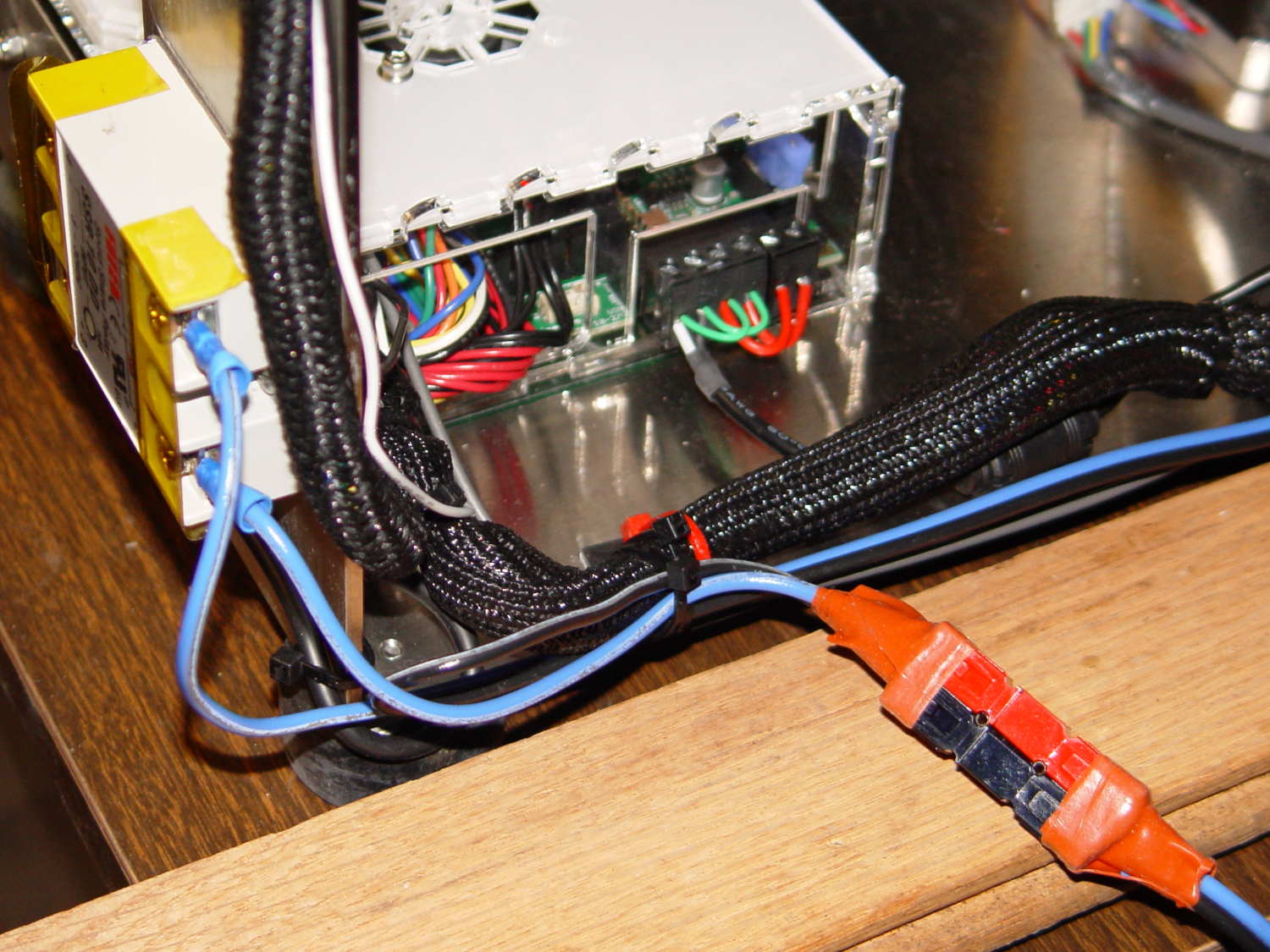
Note that you must use an external DC-to-DC solid state relay, because the Rambo controller board can’t handle anything over 24 VDC and high current loads tend to melt its Phoenix-style connectors. When you add the SSR, replace the HBP connectors with Anderson Powerpoles, use fat wires, and be done with it.
M2 HBP SSR Wiring
The M2’s Marlin firmware uses bang-bang control and tends to overshoot the setpoint; I’m not sure a few degrees makes all that much difference, particularly because it’s not measuring the temperature at the top of the glass plate.
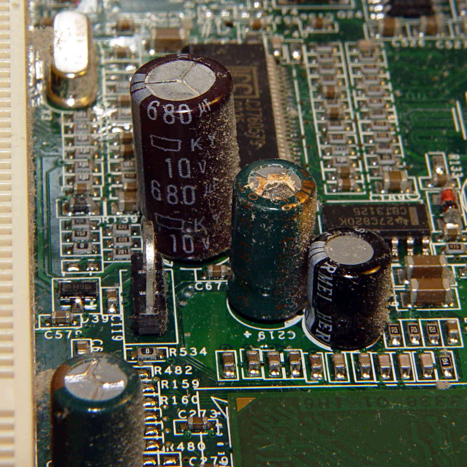
According to its Service Tag, this Dimension 2300 came off the line in late November 2002. All of the other caps on the board seemed OK, so apparently the plague affected just this lot of Hermei 470 µF 6.3 V capacitors.
Or, hey, they’re not supposed to last a dozen years and this is perfectly normal …
Because the current control loop closes through the Arduino loop(), the code’s path length limits the bandwidth. Worse, the PWM filter imposes a delay while the DC value catches up with the new duty cycle. Here’s what that looks like:
LoopStatus ILED 50 mA div – 200 50 150 25 mA
The setpoint current for this pulse is 200 mA, ramping upward from 50 mA. It should have started from 25 mA, but the loop really wasn’t under control here.
The top trace goes low during the drain current measurement, which occurs just before the code nudges the gate drive by 1 PWM count to reduce the error between the setpoint and the measurement. A delay(1) after each PWM change, plus the inherent delay due to all the program statements, produces an update every 1.7 ms, more or less.
Even at that low rate, the current overshoots by 50 mA before the loop can tamp it down again. The current varies by 200 mA for 7 PWM counts, call it 30 mA per count at the high end, so overshooting by 50 mA comes with the territory. There’s just not a lot of resolution available.
The program reads each pulse duration and amplitude from an array-of-structs, so it’s a simple matter of software to save the gate drive voltage at the end of each pulse and restore it when that pulse comes around on the guitar again:
	if (millis() >= (EventStart + (unsigned long)Events[EventIndex].duration)) {
		Events[EventIndex].drive_a = VGateDriveA;						// save drive voltages
		Events[EventIndex].drive_b = VGateDriveB;

        if (++EventIndex > MAX_EVENT_INDEX)								// step to next event
		    EventIndex = 0;

		VGateDriveA = Events[EventIndex].drive_a;						// restore previous drives
		VGateDriveB = Events[EventIndex].drive_b;

		SetPWMVoltage(PIN_SET_VGATE_A,VGateDriveA);
		SetPWMVoltage(PIN_SET_VGATE_B,VGateDriveB);

		delay(PWM_Settle);

		digitalWrite(PIN_ENABLE_A,Events[EventIndex].en_a);				// enable gates for new state
		digitalWrite(PIN_ENABLE_B,Events[EventIndex].en_b);

        NeedHallNull = !(Events[EventIndex].en_a || Events[EventIndex].en_b);	// null sensor if all off

		EventStart = millis();                                          // record start time
	}
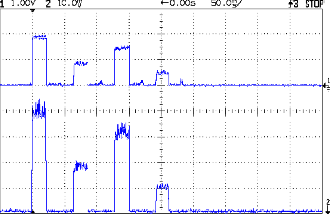
… which produces this happy result, with a different time scale to show all four pulses in the array:
I Sense Amp ILED 50 mA div – 200 100 150 50 mA
The top trace shows the current amp output that goes into the Arduino analog input and the bottom trace shows the MOSFET drain current. Notice those nice, crisp edges with a nearly complete lack of current adjustment.
The small bumps in the amp output just after the LED turns off happen while the the code nulls the Hall effect sensor offset. Whenever the LEDs turn off, the code nulls the sensor, which is probably excessive; it really doesn’t have much else to do, so why not?
This trickery doesn’t improve the loop bandwidth at all, because the code must still drag the current to meet each setpoint, but now that happens only when the pulse first appears. After a few blinks, the current stabilizes at the setpoint and the loop need handle only slight variations due to temperature or battery voltage changes.
Speaking of voltages:
VDS ILED 50 mA div – 200 100 150 50 mA
The top trace now shows the MOSFET drain voltage and the bottom still has the LED current. There’s only 650 mV of difference at the drain for currents of 50 mA and 200 mA through the LEDs, with about 1 V of headroom remaining at 200 mA.
The power supply delivers 7.4 V to the anode end of the LEDs, so they drop 6.3 V @ 200 mA and 5.7 V @ 50 mA. Some informal knob twiddling suggests that the MOSFET loses control authority at about 6.5 V, so, given that there’s not much energy in the battery below 7.0 V anyway, the program could limit the maximum current to 50 mA when the battery hits 7 V, regain 650 mV of headroom, and run at reduced brightness (and perhaps a different blink pattern) until the battery drops to 6.5 V, at which point the lights go out.
There’s more improvement to be had in the code, but those pulses look much better.
(If you’re keeping track, as I generally don’t, this is Post Number 2048: love those round numbers!)
The original 32 kHz PWM produced plenty of ripple in the LED current:
VG 1193 mV – ID 50 mA-div – 1 ms PWM filter
Using 64 kHz PWM requires putting the timers in Fast PWM Mode:
Timer 1: Mode 5 = Fast PWM, 8-bit resolution
Timer 2: Mode 3
The Arduino code that does the deed:
// Timer 1: PWM 9 PWM 10 - Hall offset
TCCR1A = B10000001; // Mode 5 = fast 8-bit PWM with TOP=FF
TCCR1B = B00001001; // ... WGM, 1:1 clock scale -> 64 kHz

// Timer 2: PWM3 PWM11 - MOSFET gate drive A, B
TCCR2A = B10100011; // Mode 3 = fast PWM with TOP=FF
TCCR2B = B00000001; // ... 1:1 clock scale -> 64 kHz

analogWrite(PIN_SET_VGATE_A,0); // force gate voltage = 0
analogWrite(PIN_SET_VGATE_B,0);
With that in hand, things look a lot better:
PWM Ripple – 64 kHz 200 mA
The oscilloscope scales aren’t the same and the PWM duty cycle isn’t quite the same, but the LED current ripple drops by a little more than the factor of two you’d expect.
The rise and fall times for the LEDs on the over-the-top blinky taillight left a bit to be desired, at least if you were interested in short pulses:
VG 1193 mV – ID 50 mA-div – 1 ms PWM filter – overview
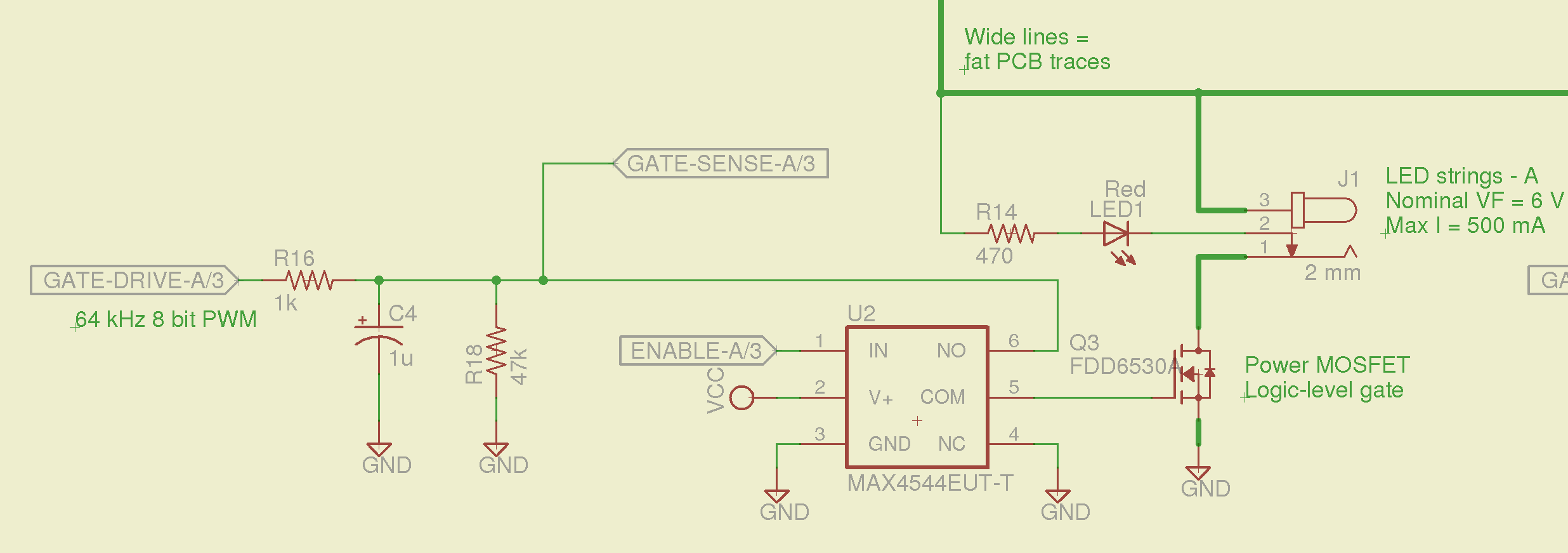
So I spliced an analog switch between the PWM filter and the gate, with inputs selecting ground and the PWM drive voltage:
Switched MOSFET gate – analog switch schematic
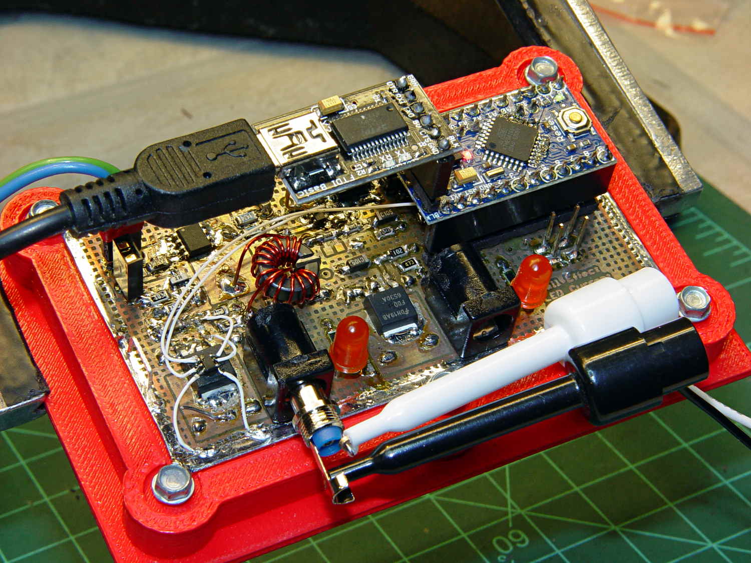
This being a prototype, that involved epoxying a SOT23-6 package atop the MOSFET, with flying wires all over the PCB:
Hall Effect PCB – MOSFET gate switch
It works pretty well:
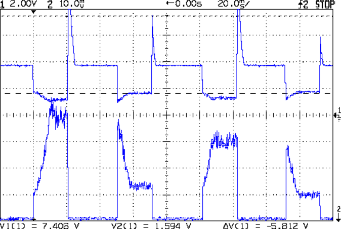
VDS ILED 50 mA div – 200 50 150 25 mA
The top trace is the drain voltage and the bottom trace is the LED current at 50 mA/div.
The current transitions come out vertical at any sweep speed, even through the Tek Hall effect current probe. The pulses would be rectangular if I weren’t changing the current for each one.
The current feedback loop closes through the Arduino’s main loop, which includes a 1 ms delay after each PWM output change before measuring the LED current. As a result, each loop takes just under 2 ms, but, fortunately, ramping from 25 mA (in the last pulse) to 200 mA (in the first pulse) requires less than 10 PWM increments; you can see the stairsteps if you squint.
Next up: bump the PWM to 64 kHz (from 32 kHz) and rip out the pull-down resistor that used to hold the gate near ground when the output floated as an input. That should improve the output ripple caused by the MOSFET’s bias as a perfectly serviceable linear amplifier.
The control loop now fetches durations & currents from an array-of-structs, so I can customize each pulse. An obvious enhancement: remember the gate drive that produced a given current, then restore the corresponding value as the starting PWM setting for each pulse, so the loop begins closer to reality. The gate drive varies with temperature and suchlike, so it can’t be a compile-time constant, but maybe the startup routine could preload the array / list / cache with values taken from a “lamp test”.
Four close-together flashes repeating at about 2 Hz, even with two runt pulses, turn the LEDs into a real eye magnet…
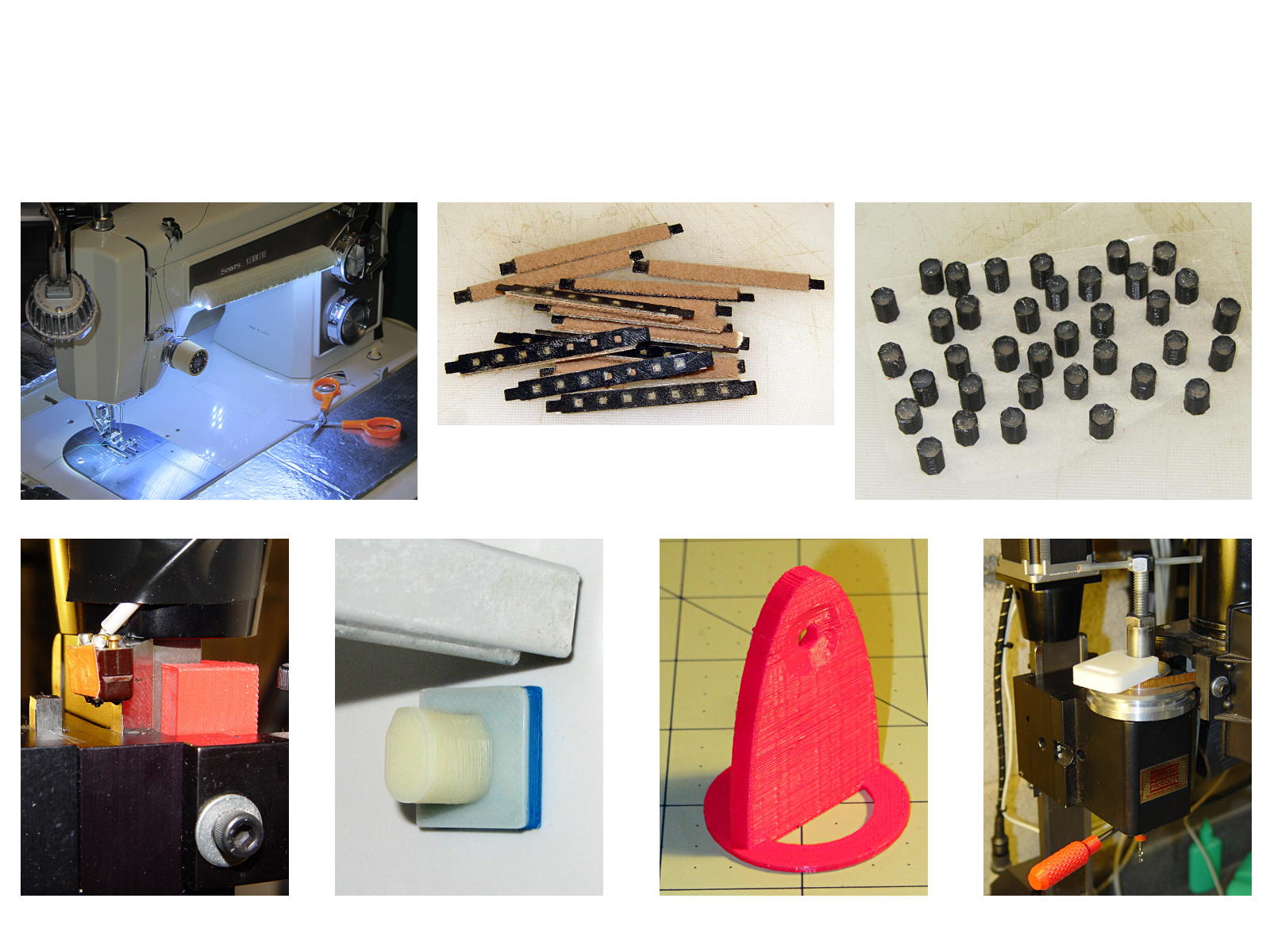
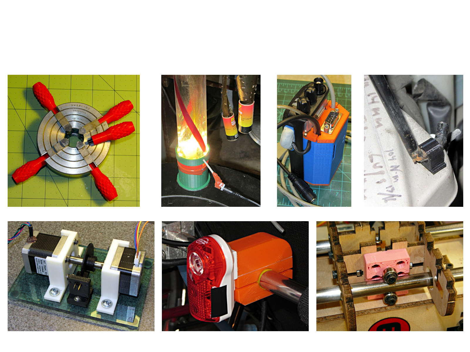
The whole reason I got a 3D printer in the first place was to make things that would otherwise be too difficult or tedious by hand or on a CNC mill. Most of the things I make look like brackets and I don’t do sculptures … this stuff solves problems!
Being able to go from “I need a part shaped like that” to holding the thing in my hand a few hours (or, for complex designs, days) later is empowering. Being able to adjust a dimension by changing the source code and “recompiling” to get a new part is wonderful.
These five slides from the presentation show my answers to the question “Why would anyone want a 3D printer?” Clicky for more dots.
Things I Designed – 1Things I Designed – 2Things I Designed – 3Things I Designed – 4Things I Designed – 5