The Smell of Molten Projects in the Morning

Ed Nisley's Blog: Shop notes, electronics, firmware, machinery, 3D printing, laser cuttery, and curiosities. Contents: 100% human thinking, 0% AI slop.

Category: Electronics Workbench

Electrical & Electronic gadgets

  • Dell Optiplex GX270 Power Control PCB Connections

    The general idea is to gut an old Dell Optiplex GX270 and stuff the high-voltage parts of the sewing machine controller inside a well constructed and solidly grounded metal shield inside a not-too-ugly plastic box. It’d be nice to reuse the power control button and status LEDs on the front panel…

    The few parts on the front of the through-hole board:

    Dell Power Button PCB - component
    Dell Power Button PCB – component

    The copper side, with annotations:

    Dell Power Button PCB - copper
    Dell Power Button PCB – copper

    The red tracer on the ribbon cable goes to Pin 1, which is a blind key on the PCB.

    The LEDs do not have ballast resistors, so those must go on a circuit board somewhere else.

    The connections:

    16 14 12 10 8 6 4 2
    Gnd nc nc nc nc HD+ HD- Button+
    Gnd nc Gnd Pwr Y+ Gnd Pwr G+ Gnd Key
    15 13 11 9 7 5 3 1


  • Eroded PTT Cable

    While installing new underseat packs (about which, more later) on my Tour Easy, I discovered a bight of PTT cable had been touching the top of the chain:

    Eroded PTT cable - Tour Easy
    Eroded PTT cable – Tour Easy

    The gentle ripples to the right of the worn-through section seem particularly nice; you couldn’t do that deliberately if you had to.

    This section of cable should have been taped to the upper frame bars. It’s hidden under the seat, just in front of the rear fender, and between the under-seat packs, so it’s basically invisible from any angle.

    Soooo, that probably explains a bit of the intermittent trouble I’d been having with the PTT switch, although most of it came from the corroded switch contacts.

    Rather than replace the whole cable, I cut out the eroded section, spliced the conductors, and taped it firmly back on the tubes.

  • Dell Power Supply: Extracting Some AC

    The case from a Dell Optiplex GX270 will hold the Kenmore 158 sewing machine’s motor control electronics, because it has a well-grounded metal box inside the plastic shell that will protect fragile humans from line voltages. The GX270 power supply will suffice for the usual stuff, but the bridge rectifier, power transistor, and suchlike require a direct connection to the AC line.

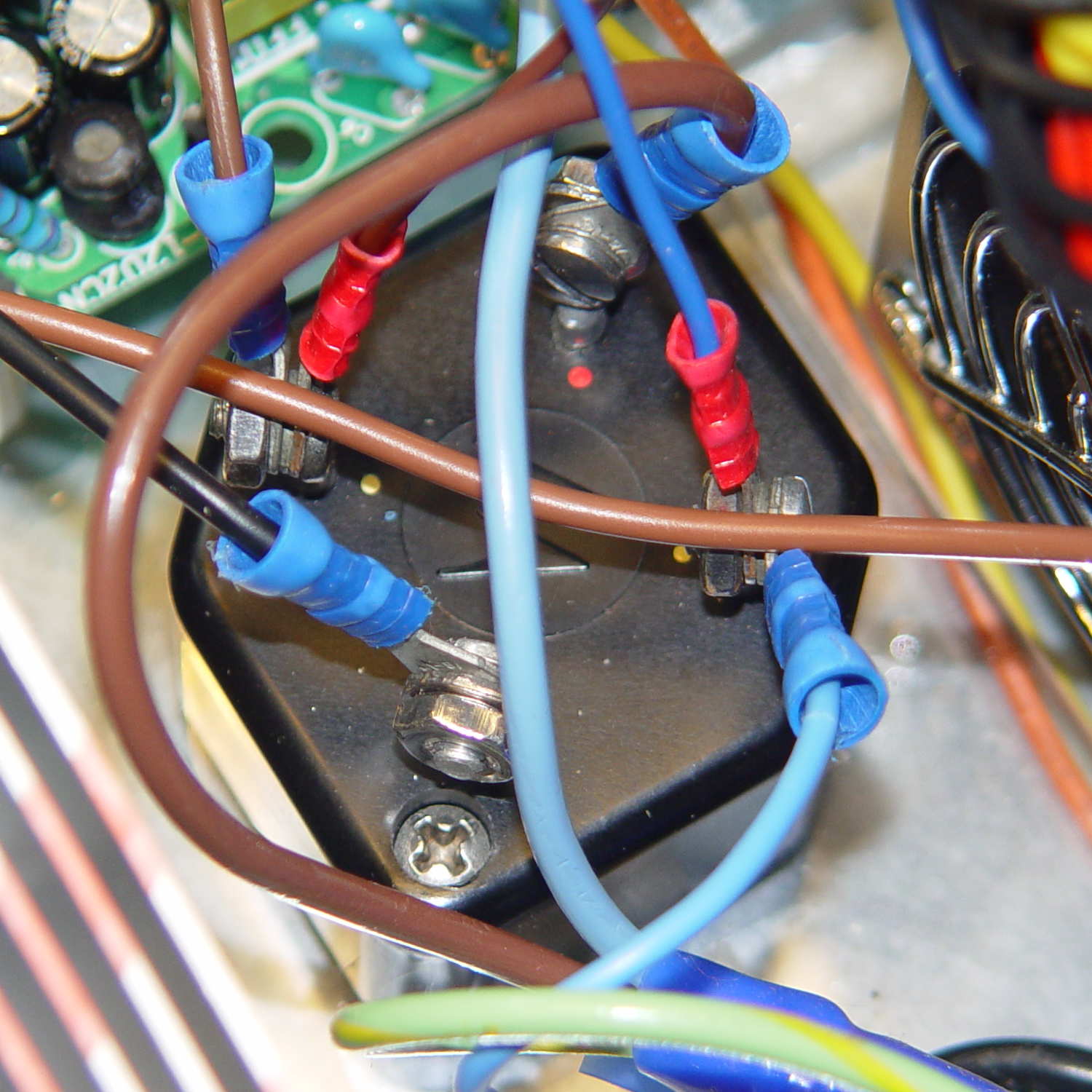
    Rather than add another plug, I soldered a nice two-wire line cord to the IEC socket terminals inside the GX270’s power supply:

    Modified Dell power supply - interior
    Modified Dell power supply – interior

    The cord follows the IEC/EU standard color code:

    • Blue – neutral
    • Brown – hot

    The power supply follows the US standard color code:

    • White – neutral
    • Black – hot

    The nice thing about standard color codes: everybody can have one!

    The yellow cable tie anchors the cord to a metal tab that, when bent at right angles, provides a convenient exit from the power supply at exactly the right location:

    Modified Dell power supply - AC cord exit
    Modified Dell power supply – AC cord exit

    The power supply mounts with the label facing inward, directly adjacent to the PCI slot covers. The new cord emerges near the bottom, inside the recess that formerly accommodated the board.

    Definitely not UL approved, but we’re well beyond that stage anyway…

  • Tour Easy: Push-to-Talk Switch Rework

    The handlebar-mounted PTT button for the amateur radio on my bike once again went toes-up, most like due to the accumlation of road dust and rainwater over the years. Rather than replace the switch, which would require peeling off a massive glob of hot melt glue and resoldering the wires, I just carved the tops off the rivets holding the cover in place, pried off the cover, and removed the button to reveal the top of the switch dome:

    Handlebar PTT switch - corroded dome
    Handlebar PTT switch – corroded dome

    Blech!

    The dome flexes outward to contact the (rather crusty) terminals on either side, so all the action happens under the dome.

    A lineup of the plastic button, the inverted dome, and the cover plate:

    Handlebar PTT switch - components
    Handlebar PTT switch – components

    The top and bottom of the dome show some grit: that’s where it contacted the switch terminals.

    Wiping the crud out of the switch body, scrubulating everything with contact cleaner, and putting it all back together restored the switch to working order. There’s (once again) a snippet of Kapton tape over the cover holding it in place, but I don’t expect this to last very long:

    Handlebar PTT switch - kapton cover
    Handlebar PTT switch – kapton cover

    But it works well enough for now …

  • ET227 Transistor DC Current Gain Variation

    A Squidwrench Weekly Doings being useful for short-attention-span projects, I measured the DC current gain for all five ET227 transistors. The test conditions fall far below the ET227’s 1 kV / 100 A ratings, but they’re roughly what the sewing machine motor controller calls for.

    The transistors don’t even begin to turn on until IB gets over about 50 mA, because there’s a 13 Ω shunt resistor (as measured, for either polarity) between the base and emitter terminal:

    Fuji ET227 - equivalent circuit
    Fuji ET227 – equivalent circuit

    In the ET227’s normal use, that resistor dumps the Miller effect charge injected from the collector (with the intent of improving the switching time), but you must ram nearly 70 mA into the resistor to get 900 mV at the base, so the actual transistor base current isn’t all that high for low collector currents. But you measure gain by dividing goes-outa by goes-inta, so that’s what I’ll do.

    The ET227 needs something like IB = 30 A to switch 100 A at the collector, so a few dozen mA into that resistor rounds off to zilch for its usual driver circuit. FWIW, with IB = 30 A, VBE tops out at 2 V: the resistor carries 150 mA and dissipates 300 mW.

    Anyhow, randomly labeling the transistors from A (on the heatsink) through E, then hitching them up to a 1.8 A bench supply with a 33 Ω resistor to the base terminal provided some readings at single-digit collector voltages.

    For IB = 72 mA:

    IB IC hFE
    A 72 490 6.8
    B 73 540 7.4
    C 74 480 6.5
    D 75 440 5.9
    E 76 520 6.8

    For IB = 108 mA, with one bumped-knob outlier:

    IB IC hFE
    A 108 1220 11.3
    B 101 1190 11.8
    C 108 1280 11.9
    D 108 1170 10.8
    E 108 1320 12.2

    Although the gain around 1 A comes out slightly higher than while running the motor, it’s in the same ballpark. This is not a high-gain device: it’ll need a driver after the optoisolator to squeeze enough current through the collector.

    Eks tried to unload a huge old Tek transistor curve tracer on me that would be ideal for this sort of thing. I’m still not tempted…

  • FT82-43 Slit Toroid: Calibration

    I’d have trouble faking this with a straight face:

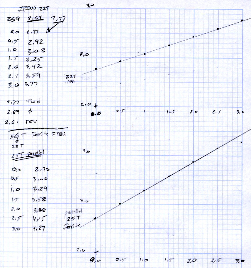
    FT82-43 - 56 turns - 24 AWG
    FT82-43 – 56 turns – 24 AWG

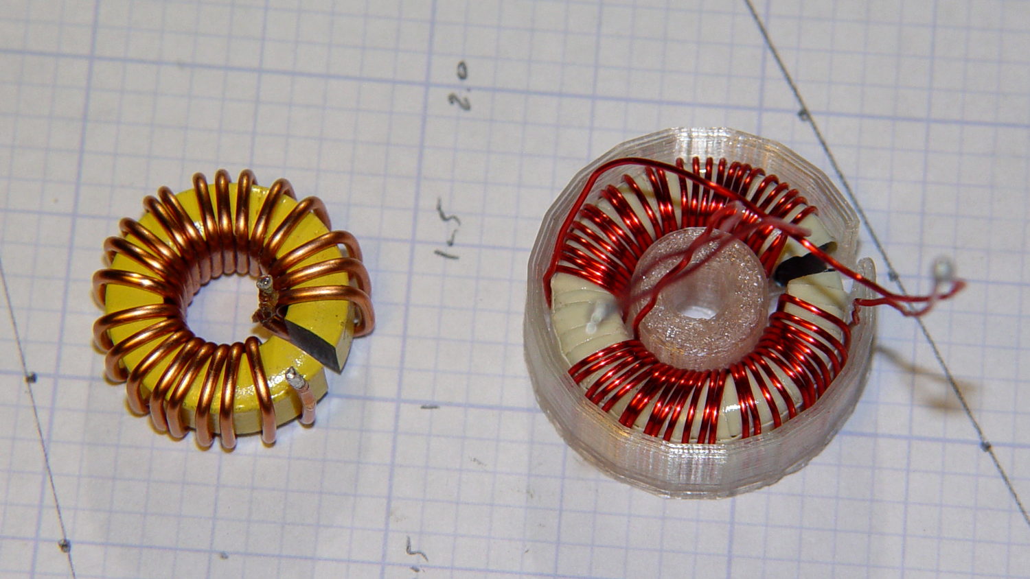
    That’s measured with the 56 turn winding connected directly to a bench power supply, cranking up the current, taking the reading, and turning the current back down again, so as to avoid cooking the poor thing inside its PLA armor:

    FT82-43 toroid - mounted
    FT82-43 toroid – mounted

    The “49E” sensor came from one of the bags of eBay fallout. They saturate around 4.25 V; the outputs above 4 V lose their linearity due to the sensor, not ferrite saturation.

    The original calculations guesstimates suggested 25 turns would produce full scale at 5 A, so 56 turns should top out at 2.2 A. Frankly, given all the imponderables in this lashup, a factor of two seems pretty close.

    Offsetting the output by -1 A would yield a 2 A range that’s just about exactly right. Unfortunately, some fiddling about with neodymium magnets suggests that you (well, I) can’t stuff enough opposing field into the slit without saturating (some part of) the ferrite core, reducing the permeability, and blowing all the assumptions.

    So that suggests a buck winding, obviously with more turns to allow less current for the same magnetizing force. Wrapping 110 turns reduces the buck current to 500 mA and assuming a bit over an inch/turn requires 10 feet, which is nearly 1 Ω of 30 AWG wire: the buck current dumps another 250 mW into (a somewhat larger version of) that PLA armor.

    Or just throw away half of the Hall effect sensor range and use an op amp along the lines of the LED current sensor.

  • NP-BX1 Lithium Batteries: 6 Month Status

    The battery capacities after six months are, of course, lower:

    Sony NP-BX1 - OEM Wasabi - 2014-08-17
    Sony NP-BX1 – OEM Wasabi – 2014-08-17

    I didn’t bring the HDR-AS30V camera along on the Hudson River ride, simply because each battery lasts about 1.5 hr in 1920×1080 @ 60 fps mode and I wasn’t up to replacing batteries during the ride, then charging all three every evening. Obviously, the camera wasn’t intended for that use case.

    Somewhat surprisingly, the Wasabi batteries deliver the same continuous run time as the Sony battery: 1:30 vs 1:33. I used 250 mA for those discharge curves, but I think something around 500 mA would better match the camera load.

    I’m sorely tempted to drill a hole in the camera’s case and wire in a honkin’ big prismatic lithium cell.