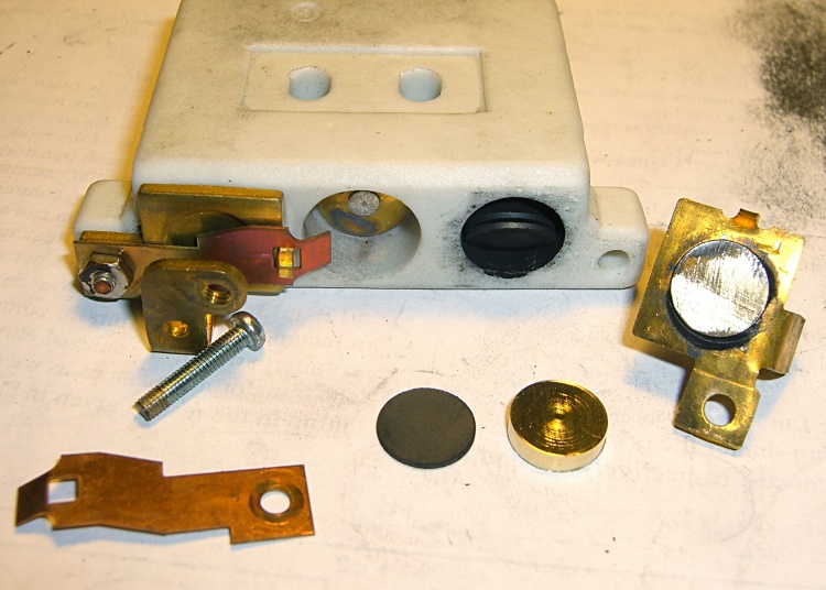
Ed Nisley's Blog: Shop notes, electronics, firmware, machinery, 3D printing, laser cuttery, and curiosities. Contents: 100% human thinking, 0% AI slop.
A four-click rotary pushbutton switch actuates the three functions (plus “off”) in sequence:
Flashlight switch – internal wiring
All three lights became intermittent, which suggested a poor return connection at the far end of the battery. The case is, of course, aluminum, with coarse-cut threads that grate as you tighten the parts. I cleaned the crud out of the threads, anointed them with Ox-Gard compound, and discovered that the laser and UV LEDs were still flaky.
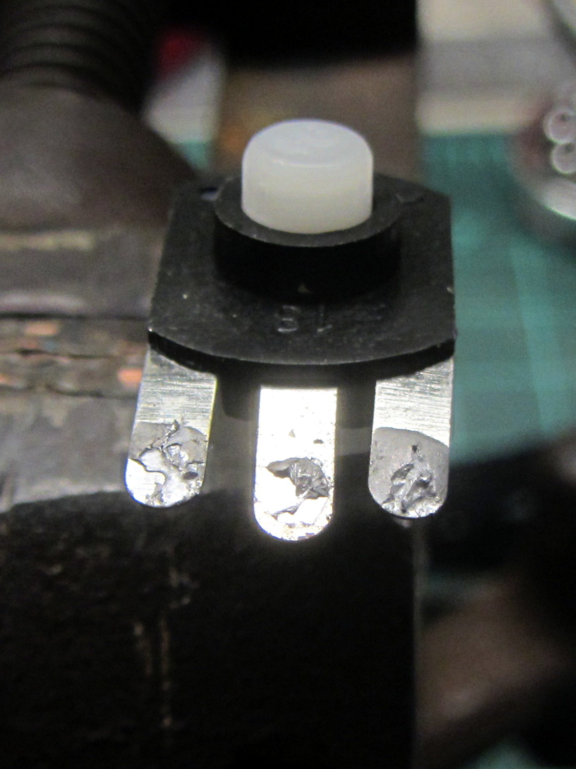
Taking the thing apart and unsoldering the switch connections revealed the problem:
Flashlight switch – bad solder joints
Yup, two lousy solder joints. They’re not exactly cold solder joints, because there’s not really a joint there to begin with; the switch tabs never got hot enough to bond with the molten solder before it cooled.
A dab of flux and touch from a hot soldering iron solved that problem.
Assemble in reverse order and it works better than it ever did before!
The Adafruit 2.8 inch TFT Touch Shield for Arduino v2 seems just about ideal for a small control panel, such as one might use with a modified sewing machine. All you need is a few on-screen buttons, a few status display, and a bit of Arduino love: what more could one ask?
So I gimmicked up some small buttons with GIMP, made two large buttons with ImageMagick, and lashed together some Arduino code based on the Adafruit demo:
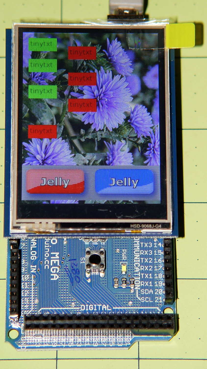
Adafruit TFT display – timing demo
The picture doesn’t do justice to the display: it’s a nice piece of hardware that produces a crisp image. The moire patterns come from the interaction of TFT display pixels / camera pixels / image resizing.
It’s not obvious from the Adafruit description, but the display is inherently portrait-mode as shown. The (0,0) origin lies in the upper left corner, just over the DC power jack, and screen buffer updates proceed left-to-right, top-to-bottom from there.
The gotcha: even with the Arduino Mega’s hardware SPI, writing the full display requires nearly 4 seconds. Yeah, slow-scan TV in action. Writing the screen with a solid color requires several seconds.
After commenting out the serial tracing instructions from the Adafruit demo and tweaking a few other things, these timings apply:
-------------
Writing background
Elapsed: 3687
Writing six buttons
Elapsed: 529
Overwriting six buttons
Elapsed: 531
Rewriting buttons 10 times
Elapsed: 1767
Overwriting 2 large buttons
Elapsed: 1718
The button images come from BMP files on a MicroSD card and 8 KB of RAM won’t suffice for even a small button. Instead, the transfer loop buffers 20 pixels = 60 bytes from the card, writes them to the display, and iterates until it’s done.
Trust me on this: watching the buttons gradually change is depressing.
Yes, it could work as a control panel for the sewing machine, but it doesn’t have nearly the pep we’ve come to expect from touch-screen gadgetry. On the other paw, Arduinos are 8-bit microcontrollers teleported from the mid-90s, when crappy 20×4 LCD panels were pretty much as good as it got.
The SPI hardware clock runs at half the oscillator frequency = 16 MHz/2 = 8 MHz = 125 ns/bit. Clocking a single byte thus requires 1 µs; even allowing that each pixel = 3 bytes = 6 SPI operations, there’s a lot of software overhead ripe for the chopping block. I’d be sorely tempted to write a pair of unrolled loops that read 20 pixels and write 20 pixels with little more than a pointer increment & status spin between successive SPI transfers.
It’ll make hotshot C++ programmers flinch, but splicing all that into a single routine, throwing out all the clipping and error checking, and just getting it done might push the times down around 20 µs/pixel. Admittedly, that’s barely twice as fast, but should be less depressing.
However, even with all that effort, the time required to update the screen will clobber the motor control. You can’t devote a big fraction of a second to rewriting a button at the same time you’re monitoring the pedal position, measuring the motor speed, and updating the control voltage. That’s the same problem that makes Arduino microcontrollers inadequate for contemporary 3D printers: beyond a certain point, the hardware is fighting your efforts, not helping you get things done.
A reasonable workaround: no screen updates while the motor turns, because you shouldn’t have any hands free while you’re sewing.
The Arduino source code, hacked from the Adafruit demo:
// 2.8 inch TFT display exercise
// Crudely hacked from Adafruit demo code: spitftbitmap.ino
// 2014-07-03 Ed Nisley KE4ZNU

/***************************************************
  This is our Bitmap drawing example for the Adafruit ILI9341 Breakout and Shield
  ----> http://www.adafruit.com/products/1651

  Check out the links above for our tutorials and wiring diagrams
  These displays use SPI to communicate, 4 or 5 pins are required to
  interface (RST is optional)
  Adafruit invests time and resources providing this open source code,
  please support Adafruit and open-source hardware by purchasing
  products from Adafruit!

  Written by Limor Fried/Ladyada for Adafruit Industries.
  MIT license, all text above must be included in any redistribution
 ****************************************************/

#include <Adafruit_GFX.h>    // Core graphics library
#include "Adafruit_ILI9341.h" // Hardware-specific library
#include <SPI.h>
#include <SD.h>

#define TFT_DC 9
#define TFT_CS 10
Adafruit_ILI9341 tft = Adafruit_ILI9341(TFT_CS, TFT_DC);

#define SD_CS 4

unsigned long MillisNow, MillisThen;

void setup(void) {
  Serial.begin(115200);

  tft.begin();
  tft.fillScreen(ILI9341_BLACK);

  Serial.print(F("Initializing SD card..."));
  if (!SD.begin(SD_CS)) {
    Serial.println(F("failed!"));
  }
  Serial.println(F("OK!"));

}

void loop() {
  Serial.println(F("--------------"));
  Serial.println(F("Writing background"));
  MillisThen = millis();

  bmpDraw("Test1.bmp", 0, 0);

  MillisNow = millis();
  Serial.print(F("" Elapsed: ""));
  Serial.println(MillisNow - MillisThen);

  Serial.println(F("Writing 6 small buttons"));
  MillisThen = millis();

  bmpDraw("Red50x25.bmp",10,10);
  bmpDraw("Red50x25.bmp",10,50);
  bmpDraw("Red50x25.bmp",10,100);

  bmpDraw("Grn50x25.bmp",80,25);
  bmpDraw("Grn50x25.bmp",80,75);
  bmpDraw("Grn50x25.bmp",80,125);

  MillisNow = millis();
  Serial.print(F("" Elapsed: ""));
  Serial.println(MillisNow - MillisThen);

  Serial.println(F("Overwriting 6 small buttons"));
  MillisThen = millis();

  bmpDraw("Grn50x25.bmp",10,10);
  bmpDraw("Grn50x25.bmp",10,50);
  bmpDraw("Grn50x25.bmp",10,100);

  bmpDraw("Red50x25.bmp",80,25);
  bmpDraw("Red50x25.bmp",80,75);
  bmpDraw("Red50x25.bmp",80,125);

  MillisNow = millis();
  Serial.print(F("" Elapsed: ""));
  Serial.println(MillisNow - MillisThen);

  Serial.println(F("Writing small button 10x2 times"));
  MillisThen = millis();

  for (byte i=0; i<10; i++) {
    bmpDraw("Grn50x25.bmp",10,175);
    bmpDraw("Red50x25.bmp",10,175);
  }

  MillisNow = millis();
  Serial.print(F("" Elapsed: ""));
  Serial.println(MillisNow - MillisThen);

  Serial.println(F("Overwriting 2 large buttons"));
  MillisThen = millis();

  bmpDraw("GelDn.bmp",0,250);
  bmpDraw("GelUp.bmp",0,250);

  bmpDraw("GelUp.bmp",120,250);
  bmpDraw("GelDn.bmp",120,250);

  MillisNow = millis();
  Serial.print(F("" Elapsed: ""));
  Serial.println(MillisNow - MillisThen);

}

// This function opens a Windows Bitmap (BMP) file and
// displays it at the given coordinates.  It's sped up
// by reading many pixels worth of data at a time
// (rather than pixel by pixel).  Increasing the buffer
// size takes more of the Arduino's precious RAM but
// makes loading a little faster.  20 pixels seems a
// good balance.

#define BUFFPIXEL 20

void bmpDraw(char *filename, uint8_t x, uint16_t y) {

  File     bmpFile;
  int      bmpWidth, bmpHeight;   // W+H in pixels
  uint8_t  bmpDepth;              // Bit depth (currently must be 24)
  uint32_t bmpImageoffset;        // Start of image data in file
  uint32_t rowSize;               // Not always = bmpWidth; may have padding
  uint8_t  sdbuffer[3*BUFFPIXEL]; // pixel buffer (R+G+B per pixel)
  uint8_t  buffidx = sizeof(sdbuffer); // Current position in sdbuffer
  boolean  goodBmp = false;       // Set to true on valid header parse
  boolean  flip    = true;        // BMP is stored bottom-to-top
  int      w, h, row, col;
  uint8_t  r, g, b;
  uint32_t pos = 0, startTime = millis();

  if((x >= tft.width()) || (y >= tft.height())) return;

//  Serial.println();
//  Serial.print(F("Loading image '"));
//  Serial.print(filename);
//  Serial.println('\'');

  // Open requested file on SD card
  if ((bmpFile = SD.open(filename)) == NULL) {
//    Serial.print(F("File not found"));
    return;
  }

  // Parse BMP header
  if(read16(bmpFile) == 0x4D42) { // BMP signature
//    Serial.print(F("File size: "));
//	Serial.println(read32(bmpFile));
	read32(bmpFile);
    (void)read32(bmpFile); // Read & ignore creator bytes
    bmpImageoffset = read32(bmpFile); // Start of image data
//    Serial.print(F("Image Offset: ")); Serial.println(bmpImageoffset, DEC);
    // Read DIB header
//    Serial.print(F("Header size: "));
//	Serial.println(read32(bmpFile));
	read32(bmpFile);
    bmpWidth  = read32(bmpFile);
    bmpHeight = read32(bmpFile);
    if(read16(bmpFile) == 1) { // # planes -- must be '1'
      bmpDepth = read16(bmpFile); // bits per pixel
//      Serial.print(F("Bit Depth: ")); Serial.println(bmpDepth);
      if((bmpDepth == 24) && (read32(bmpFile) == 0)) { // 0 = uncompressed

        goodBmp = true; // Supported BMP format -- proceed!
//        Serial.print(F("Image size: "));
//        Serial.print(bmpWidth);
//        Serial.print('x');
//        Serial.println(bmpHeight);

        // BMP rows are padded (if needed) to 4-byte boundary
        rowSize = (bmpWidth * 3 + 3) & ~3;

        // If bmpHeight is negative, image is in top-down order.
        // This is not canon but has been observed in the wild.
        if(bmpHeight < 0) {
          bmpHeight = -bmpHeight;
          flip      = false;
        }

        // Crop area to be loaded
        w = bmpWidth;
        h = bmpHeight;
        if((x+w-1) >= tft.width())  w = tft.width()  - x;
        if((y+h-1) >= tft.height()) h = tft.height() - y;

        // Set TFT address window to clipped image bounds
        tft.setAddrWindow(x, y, x+w-1, y+h-1);

        for (row=0; row<h; row++) { // For each scanline...

          // Seek to start of scan line.  It might seem labor-
          // intensive to be doing this on every line, but this
          // method covers a lot of gritty details like cropping
          // and scanline padding.  Also, the seek only takes
          // place if the file position actually needs to change
          // (avoids a lot of cluster math in SD library).
          if(flip) // Bitmap is stored bottom-to-top order (normal BMP)
            pos = bmpImageoffset + (bmpHeight - 1 - row) * rowSize;
          else     // Bitmap is stored top-to-bottom
            pos = bmpImageoffset + row * rowSize;
          if(bmpFile.position() != pos) { // Need seek?
            bmpFile.seek(pos);
            buffidx = sizeof(sdbuffer); // Force buffer reload
          }

          for (col=0; col<w; col++) { // For each pixel...
            // Time to read more pixel data?
            if (buffidx >= sizeof(sdbuffer)) { // Indeed
              bmpFile.read(sdbuffer, sizeof(sdbuffer));
              buffidx = 0; // Set index to beginning
            }

            // Convert pixel from BMP to TFT format, push to display
            b = sdbuffer[buffidx++];
            g = sdbuffer[buffidx++];
            r = sdbuffer[buffidx++];
            tft.pushColor(tft.color565(r,g,b));
          } // end pixel
        } // end scanline
//        Serial.print(F("Loaded in "));
//        Serial.print(millis() - startTime);
//        Serial.println("" ms"");
      } // end goodBmp
    }
  }

  bmpFile.close();
  if(!goodBmp) Serial.println(F("BMP format not recognized."));
}

// These read 16- and 32-bit types from the SD card file.
// BMP data is stored little-endian, Arduino is little-endian too.
// May need to reverse subscript order if porting elsewhere.

uint16_t read16(File &f) {
  uint16_t result;
  ((uint8_t *)&result)[0] = f.read(); // LSB
  ((uint8_t *)&result)[1] = f.read(); // MSB
  return result;
}

uint32_t read32(File &f) {
  uint32_t result;
  ((uint8_t *)&result)[0] = f.read(); // LSB
  ((uint8_t *)&result)[1] = f.read();
  ((uint8_t *)&result)[2] = f.read();
  ((uint8_t *)&result)[3] = f.read(); // MSB
  return result;
}
Eks found some heavy-duty ET227 NPN transistors in his heap and put them on the basement steps for me … months ago, because he knew I’d be needing them.
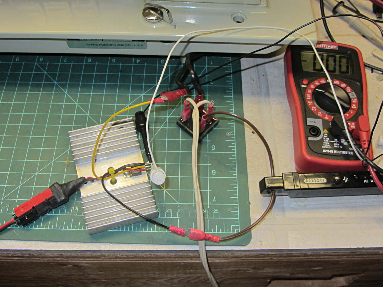
Mounting an ET227 on a massive CPU heatsink with thermal compound and wiring it in place of the failed MOSFET produces this lashup:
Kenmore 158 – ET227 FW drive
The base drive comes directly from a bench supply and the collector sees full-wave rectified 120 VAC from the isolated Variac. The maximum base current rating of 40 A at DC suggests it’ll be difficult to screw this one up. The rectifier bridge doesn’t dissipate enough power to warm up, even without a heatsink.
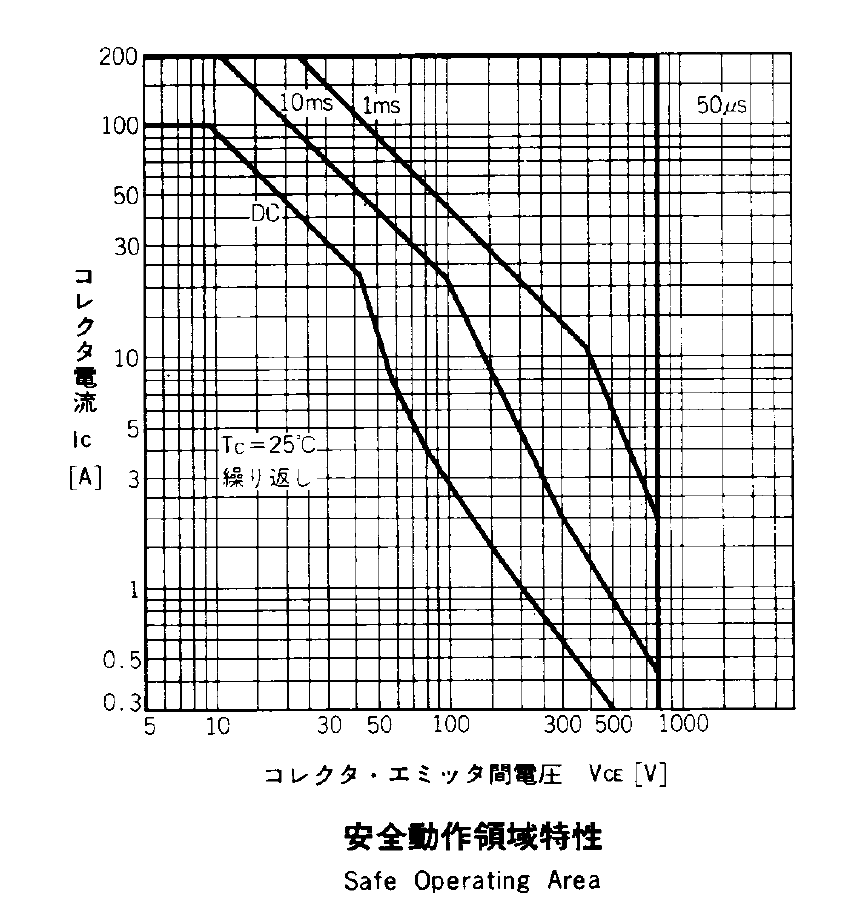
The SOA plot from the ET227 datasheet has the expected 1 kV and 100 A limits that you can’t actually reach under most conditions:
ET227 – Safe Operating Area
The Kenmore 158 motor has a DC resistance of about 50 Ω, so the locked-rotor current won’t be more than about 3 A. The motor current runs around 700 mA with a voltage drop across the transistor ranging from 20 V to 50 V at normal operating conditions, so it’s just barely within the DC SOA. So far, my efforts to kill it by stalling the motor have been unavailing; I have four spares and Eks has at least five more in his heap.
The ET227 has a 960 W (!) maximum dissipation on an ideal heatsink, so the piddly 35 W it might see here doesn’t amount to much. The heatsink should have a quiet demand-driven fan.
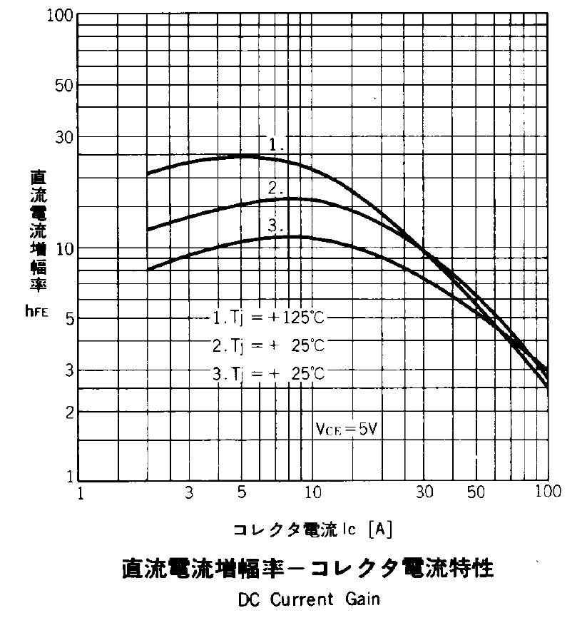
The operating current is offscale low along the left edge of the DC Current Gain plot, which suggests a DC gain under 10:
ET227 – DC Current Gain
As it turned out, the gain was around 7, with 100 mA base drive producing 700 mA of collector current at VBE = 0.9 V, although that comes from the bench supply’s low-res meters. There being an exponential relation between the bench supply’s voltage output and the transistor’s base current, along with the motor’s square-law positive feedback, speed control was mmmm touchy.
So the challenge will be stuffing 100 mA into a 1 V base voltage, with much better resolution and much less ripple than the usual Arduino PWM output, from an isolated supply. Given the amount of power I’m willing to burn in the ET227, a few more watts of base drive won’t make a bit of difference.
Perhaps the best way to handle all the nonlinearities in the current control path will be an isolated current feedback monitor. Hello, Hall effect sensors … [sigh]
At least until I blew out the MOSFET, which is about what I expected. It’s screwed to that randomly selected heatsink, with a dab of thermal compound underneath.
Incoming AC from an isolated variable transformer (basically, an isolated Variac) goes to a bridge rectifier. Rectified output: positive to the motor, motor to MOSFET drain, MOSFET source to negative.
MOSFET gate from bench supply positive and supply negative to source.
Hall effect current probe clamped around the motor current path.
The MOSFET was an IRF610: 200 V / 3.3 A. That’s under-rated for what I was doing, but I had a bunch of ’em.
I actually worked up to that mess, starting with the bare motor on the bench running from the 50 VDC supply. That sufficed to show that you can, in fact, control the motor speed by twiddling the gate voltage to regulate the current going into the motor. It also showed that a universal-wound motor’s square-law positive feedback loop will definitely require careful tuning; think of an unstable fly-by-wire airplane and you’ve got the general idea.
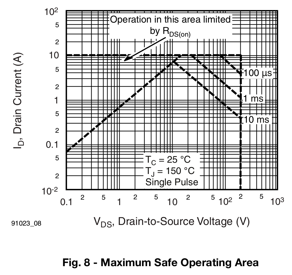
In any event, flushed with success, I ignored the safe operating area graph (from the Vishay datasheet):
IRF610 – Safe Operating Area
Drain current over half an amp at 160-ish peak volts (from rectified 120 VAC) will kill the MOSFET unless you apply it as short single pulses, not repetitive 120 Hz hammerblows.
I also ignored the transfer characteristics graph:
IRF610 – Typical Transfer Characteristics
The curve starting at the lower left should be labeled 25 °C and the other should be 150 °C. The key point is that they cross around VGS = 6.5 V, where IDS = 2 A. Below that point, the MOSFET conducts more current as it heats up… which means that if a small part of the die heats up, it will conduct more current, heat up even more, and eventually burn through.
Yes, MOSFETs can suffer thermal runaway, too.
The motor draws about half an amp while driving the sewing machine, which suggests the gate voltage will be around 5 V. In round numbers, it was 5.5 to 6 V as I twiddled the knob to maintain a constant speed.
At half an amp, the MOSFET dissipated anywhere from a bit under 1 W (from RDS(on) = 1.5 Ω to well over 25 W (while trying to maintain headway with friction on the handwheel). I ran out of fingers to record the numbers, but dropping 10 to 20 V across the MOSFET seemed typical and that turns into 5 to 10 W.
It eventually failed shorted and the sewing machine revved up to full speed. Sic transit gloria mundi.
In any event, I think the only way to have a transistor survive that sort of abuse is to start with one so grossly over-rated that it can handle a few amps at 200 V without sweating. It might actually be easier to get an ordinary NPN transistor with such ratings; using a hockey puck IGBT or some such seems like overkill.
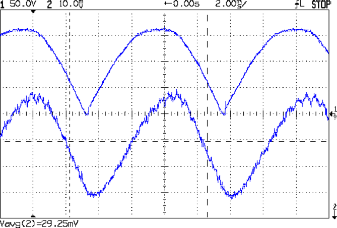
Because the universal-wound AC motorruns on DC, it will also run on full-wave rectified AC (top trace). The current waveform (bottom, 200 mA/div) never hits zero:
Rectified AC – 200 mA div – 875 RPM
Note that the current lags the voltage, as you’d expect from an inductive load.
The average current at 120 VAC rectified is about 600 mA, a bit over the current at 50 V that I measured from the DC supply while driving the sewing machine. The locked-rotor torque averages 1 A, although it’s pretty hard to hold the handwheel at full voltage.
The key advantage of rectified AC: an ordinary MOSFET can control the motor current.
Given the motor’s sensitivity to current limiting, there’s not much point in measuring the current; unlike LED brightness, the speed isn’t proportional to the current. The MOSFET must act more like the carbon pile rheostat, burning whatever voltage the motor doesn’t need to run at the selected speed, with the RPM setpoint determining the gate voltage in a closed loop.
You can detect a stall by watching the motor RPM: when that drops too far below the setpoint, it’s stalled.
The gotcha will be keeping the MOSFET within its the safe operating area at both ends of the voltage range, due to the nearly constant current at any applied voltage:
High voltage + high current hits the maximum pulsed power limit of IDSVDS
Low voltage + high current hits the minimum possible voltage of IDSRDS
I think the relatively low current and power levels will simplify that mess; offering up a sacrificial MOSFET for measurement may be in order.
On the whole, it’s looking more do-able than I thought.
For lack of anything smarter, I marked the Kenmore 158 pedal’s range of motion in 2 mm increments, starting at the top:
Kenmore 158 foot pedal – motion calibration
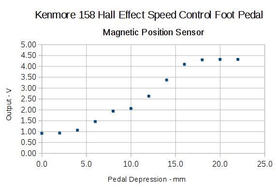
With the Hall effect sensor connected to a +5 V supply, the output looks like this:
Hall sensor output vs pedal depression
The point at 10 mm looks a bit out of place; other than that, the curve is about what you’d expect. The sensor saturates at about 0.84 V and 4.4 V, more or less, so you’re seeing the bias magnet on the low end and the main magnet on the high end.
Obviously, you shouldn’t take these measurements too seriously, but they’re in the right ballpark.
The pivot pin is 75 mm from the base of that line, so the subtended angle is more-or-less 16° = arctan(22/75), which is small enough that plotting the results as a function of the pedal angle doesn’t look any different.
Although you could linearize that, I think the curve has the right shape for a foot pedal speed control: it starts slowly and tapers off smoothly at the high end.
I think I could add a few more millimeters of magnet travel, but this will certainly suffice to get the crash test dummy running.
Given the troubles we’ve had with that thing, using it as an input device isn’t going to happen.
More modern “digital” sewing machines seem to use linear potentiometers or analog optical sensors; retrofitting that old housing seems difficult, at best, because the actuator has barely 15 mm of travel. I’m sure somebody could conjure up a bell crank to amplify the mechanical motion, but that ain’t me.
This doodle shows the rudiments of an alternative:
Hall effect distance sensor – original doodle
The general idea is to have the existing cross bar / roller move a magnet relative to an analog Hall effect sensor: closer to sensor = higher magnetic field = higher sensor output voltage. Ideally, the magnet provides enough field to max out the sensor just before the pedal reaches the limit of its travel, so the magnet never quite touches the sensor.
An optical wedge would serve a similar function, but this pretty much eliminates all the critical alignment & focusing & friction issues. Plus, I have a bunch of analog Hall effect sensors…
I have a stock of telescoping brass tubing, so the inner tube slides over the 4 mm screw that threads into the existing hardware, replacing the old shaft. That tube slides inside an outer tube that’s aligned in a block attached to the pedal frame; an epoxy blob holds it in position. The inner tube should have a nut on the left end to allow adjusting the rest position.
The Hall effect sensors have a zero-field bias at about VCC/2, so a smaller opposing (and fixed) bias magnet on the far side of the sensor pushes the output voltage to the lower limit. The adjusting screw on that side sets the bias level, if that’s needed.
A spring that’s not shown pushes the cross bar away from the block holding the outer tube and sensor; that’s what restores the magnet to its rest position when the pedal is up.
This being the age of rapid prototyping:
Foot Control Sensor Mount – solid model – top
The bottom view shows an opening for the epoxy blob halfway between the rear wall and the opening for the magnet and Hall effect sensor:
Foot Control Sensor Mount – solid model – bottom
Two bosses inside the pedal base fit into those rectangular cutouts, with the centerline of the tubing at the top of the bosses.
The inner brass tube holds the outer tube in the proper alignment while the epoxy slab cures:
Kenmore 158 – Hall speed control – tubing fit
Fortunately, two of the neodymium magnets in my collection worked out perfectly as the main and bias magnets. The smaller bias magnet just barely saturates the output when epoxied to the back of the sensor and the larger magnet has about 15 mm of active range.
The assembly sequence required half a dozen separate epoxy applications; I used quick-curing clear epoxy, rather than my usual JB Weld, because this isn’t the place for a steel filled epoxy. The final step put a washer on the back of the inner tube to hold the spring in place, with the Hall effect sensor invisible under the wad of closed-cell foam at the bottom:
Kenmore 158 – Hall speed control – epoxy curing
The spring comes from the Big Box o’ Medium Springs, which contains a few more just like it.
That solid model and the OpenSCAD code below include several refinements that don’t appear in the photos. In particular, the graceful slope on the top front will look a whole lot better than the abrasive adjustment required to fit the chunky first version into the pedal case:
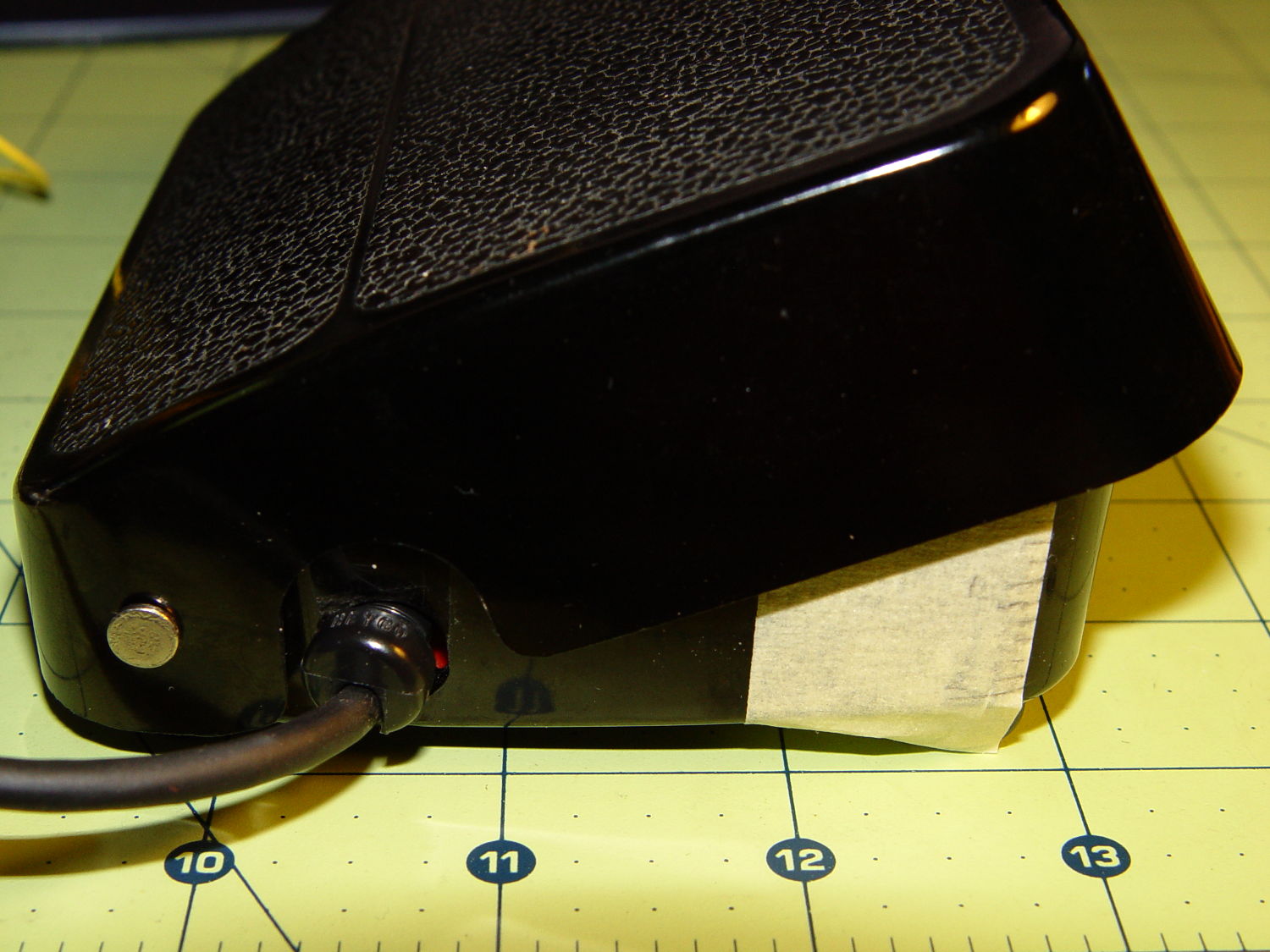
Kenmore 158 – Hall speed control – prototype interior
On the other paw, that’s what rapid prototyping is all about. I had no way to measure that dimension, but building one to figure it worked pretty well.
Things that may / will need tweaking:
The centerline of the tubing lies on the same plane as the tops of the bosses under those three screws, but the bosses are not particularly flat. Perhaps some setscrews to fine-tune the height and front-to-back tilt angle?
The sketch had adjustable magnet positions; the as-built hardware doesn’t. It’s not clear they’re needed, although that depends on having exactly the right magnets.
The screws are #4 sheet metal and fit nicely into the metric holes; the original screws held a thin aluminum bracket in place, not that chunky block. I could recess the heads, but …
A 3D printed clamp holding the cable and strain relief bushing in place would be cuter than the sheet metal strap I bashed from scrap.
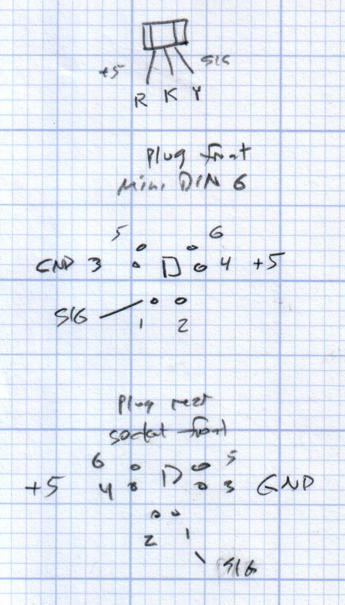
The far end of the cable terminates in a 6-pin mini-DIN connector, left over from the days when PCs (remember PCs?) had PS/2 mice & keyboards:
Kenmore 158 Improved Speed Control Pedal – cable wiring diagram
I’ll eventually put the emitter resistor into the circuit; these sensors work fine without it. The cable provides electrostatic shielding and I’m hoping the impedance is low enough that the motor won’t induce any noise. In any event, some low-pass filtering won’t slow down the response enough to notice.
Next, some measurements…
The OpenSCAD source code:
// Foot Control Sensor Mount
// Ed Nisley - KE4ZNU - June 2014

Layout = "Show";			// Plate Build Show

//- Extrusion parameters must match reality!
//  Print with 4 shells and 3 solid layers

ThreadThick = 0.20;
ThreadWidth = 0.40;

HoleWindage = 0.2;			// extra clearance

Protrusion = 0.1;			// make holes end cleanly

AlignPinOD = 1.70;			// assembly alignment pins: filament dia

function IntegerMultiple(Size,Unit) = Unit * ceil(Size / Unit);

//----------------------
// Dimensions
// Origin at center front edge of plate
//  Z = bottom surface

PlateSize = [85.0,53.0,15.0];						// overall plate size
MidZ = PlateSize[2]/2;								//  height of spring midline
PlateCornerRadius = 1.5;

FrontBevel = [0.0,15.0,5.5];						// Y from front, Z from centerline

ScrewHolesOC = [[-75.0/2,(37.0 - 14.0/2)],[-75.0/2,(37.0 + 14.0/2)],[75.0/2,37.0]];
ScrewHoleDia = 4.0;									// allow alignment slop around 3 mm / #4 screws

BossSize = [[12.0,28.0],[12.0,27.0]];				// mounting bosses: L R
BossOC = [[-75.0/2,37.0],[75.0/2,37.0]];

Stroke = 15.0;										// foot pedal actuation distance

Bushing = [5.6,23.0];								// outer brass tube
MainMagnet = [10.0,5.0];							// magnet on pushrod
BiasMagnet = [5.0,2.0];								// bias magnet behind Hall effect sensor
Spring = [9.0,8.0];									// recess for pushrod retracting spring
Washer = [10.0,1.0];								// recess for washer atop pushrod

OD = 0;												// subscripts for cylindrical objects
LEN = 1;

SensorThick = 2.0;									// Hall effect sensor on bias magnet
FilletLength = 0.75;								// glue fillet on main magnet

//----------------------
// Useful routines

module PolyCyl(Dia,Height,ForceSides=0) {			// based on nophead's polyholes

  Sides = (ForceSides != 0) ? ForceSides : (ceil(Dia) + 2);

  FixDia = Dia / cos(180/Sides);

  cylinder(r=(FixDia + HoleWindage)/2,
           h=Height,
           $fn=Sides);
}

module ShowPegGrid(Space = 10.0,Size = 1.0) {

  RangeX = floor(100 / Space);
  RangeY = floor(125 / Space);

	for (x=[-RangeX:RangeX])
	  for (y=[-RangeY:RangeY])
		translate([x*Space,y*Space,Size/2])
		  %cube(Size,center=true);

}

//----------------------
// Basic plate shape

module Plate() {

R = PlateCornerRadius;
Px = PlateSize[0]/2 - R;
Py = PlateSize[1] - R;
Sides = 4*4;

BevelAngle = atan2((MidZ - FrontBevel[2]),FrontBevel[1]);

echo("Bevel angle: ",BevelAngle);

	difference() {
		linear_extrude(height = PlateSize[2]) {
			hull() {
				translate([-Px,Py])
					circle(r=R,$fn=Sides);
				translate([Px,Py])
					circle(r=R,$fn=Sides);
				translate([Px,R])
					circle(r=R,$fn=Sides);
				translate([-(20-R),R])			// avoid left front boss
					circle(r=R,$fn=Sides);
				translate([-Px,20+R])			// avoid left front boss
					circle(r=R,$fn=Sides);
			}
		}

		translate([0,0,-Protrusion])						// screw bosses
			linear_extrude(height = (MidZ + Protrusion),convexity=2)
				for (i=[0:1])
					translate(BossOC[i])
						square(BossSize[i],center=true);

		translate([0,0,-Protrusion])						// plate mounting screws
			linear_extrude(height = 2*PlateSize[2] + Protrusion,convexity=3)
				for (i=[0:2])
					translate(ScrewHolesOC[i])
						rotate(180/6)
							circle(d=ScrewHoleDia,$fn=6);

		translate([0,0,MidZ + FrontBevel[2]])		// Front bevel
			rotate([BevelAngle,0,0])
				translate([0,0,PlateSize[2]])
					cube(2*PlateSize,center=true);

	}
}

//----------------------
// Modify plate for position sensor hardware

module Sensor() {

GluePort = [1.5*Bushing[OD],Bushing[OD]/2,PlateSize[2]];	// port for glue anchor around bushing

MagnetPort = [1.5*MainMagnet[OD],
			  (Stroke + MainMagnet[LEN] + FilletLength + SensorThick),
			  (PlateSize[2] + 2*Protrusion)];

	difference() {
		Plate();

		translate([0,(PlateSize[1] - Bushing[LEN] - Protrusion),MidZ])		// bushing
			rotate([-90,0,0])
				cylinder(d=Bushing[OD],h=PlateSize[1],$fn=6);

		translate([-GluePort[0]/2,										// bushing anchor opening
				  (PlateSize[1] - 0.66*Bushing[LEN] - GluePort[1]/2),
				  MidZ - GluePort[2] + Bushing[OD]/2])
			cube(GluePort,center=false);

		translate([0,(PlateSize[1] - Bushing[LEN] - MagnetPort[1]/2),MagnetPort[2]/2 - Protrusion])
			cube(MagnetPort,center=true);

		translate([0,(PlateSize[1] - Bushing[LEN] - MagnetPort[1] + Protrusion),MidZ])
			rotate([90,0,0])
				PolyCyl(BiasMagnet[OD],BiasMagnet[LEN] + Protrusion,6);

		translate([0,(PlateSize[1] + Protrusion),MidZ])
			rotate([90,0,0]) rotate(180/8)
				PolyCyl(Spring[OD],Spring[LEN] + Protrusion,8);

		translate([0,(PlateSize[1] + Protrusion),MidZ])
			rotate([90,0,0]) rotate(180/8)
				PolyCyl(Washer[OD],Washer[LEN] + Protrusion,8);

	}
}

ShowPegGrid();

if (Layout == "Plate") {
	Plate();
}

if (Layout == "Show")
	Sensor();

if (Layout == "Build") {
	translate([0,PlateSize[1]/2,PlateSize[2]])
		rotate([180,0,0])
			Sensor();
}