The Smell of Molten Projects in the Morning

Ed Nisley's Blog: Shop notes, electronics, firmware, machinery, 3D printing, laser cuttery, and curiosities. Contents: 100% human thinking, 0% AI slop.

Category: Electronics Workbench

Electrical & Electronic gadgets

  • Hall Effect LED Current Control: 64 kHz PWM

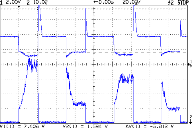
    The original 32 kHz PWM produced plenty of ripple in the LED current:

    VG 1193 mV - ID 50 mA-div - 1 ms PWM filter
    VG 1193 mV – ID 50 mA-div – 1 ms PWM filter

    Using 64 kHz PWM requires putting the timers in Fast PWM Mode:

    • Timer 1: Mode 5 = Fast PWM, 8-bit resolution
    • Timer 2: Mode 3

    The Arduino code that does the deed:

    // Timer 1: PWM 9 PWM 10 - Hall offset
    TCCR1A = B10000001; // Mode 5 = fast 8-bit PWM with TOP=FF
    TCCR1B = B00001001; // ... WGM, 1:1 clock scale -> 64 kHz
    
    // Timer 2: PWM3 PWM11 - MOSFET gate drive A, B
    TCCR2A = B10100011; // Mode 3 = fast PWM with TOP=FF
    TCCR2B = B00000001; // ... 1:1 clock scale -> 64 kHz
    
    analogWrite(PIN_SET_VGATE_A,0); // force gate voltage = 0
    analogWrite(PIN_SET_VGATE_B,0);
    

    With that in hand, things look a lot better:

    PWM Ripple - 64 kHz 200 mA
    PWM Ripple – 64 kHz 200 mA

    The oscilloscope scales aren’t the same and the PWM duty cycle isn’t quite the same, but the LED current ripple drops by a little more than the factor of two you’d expect.

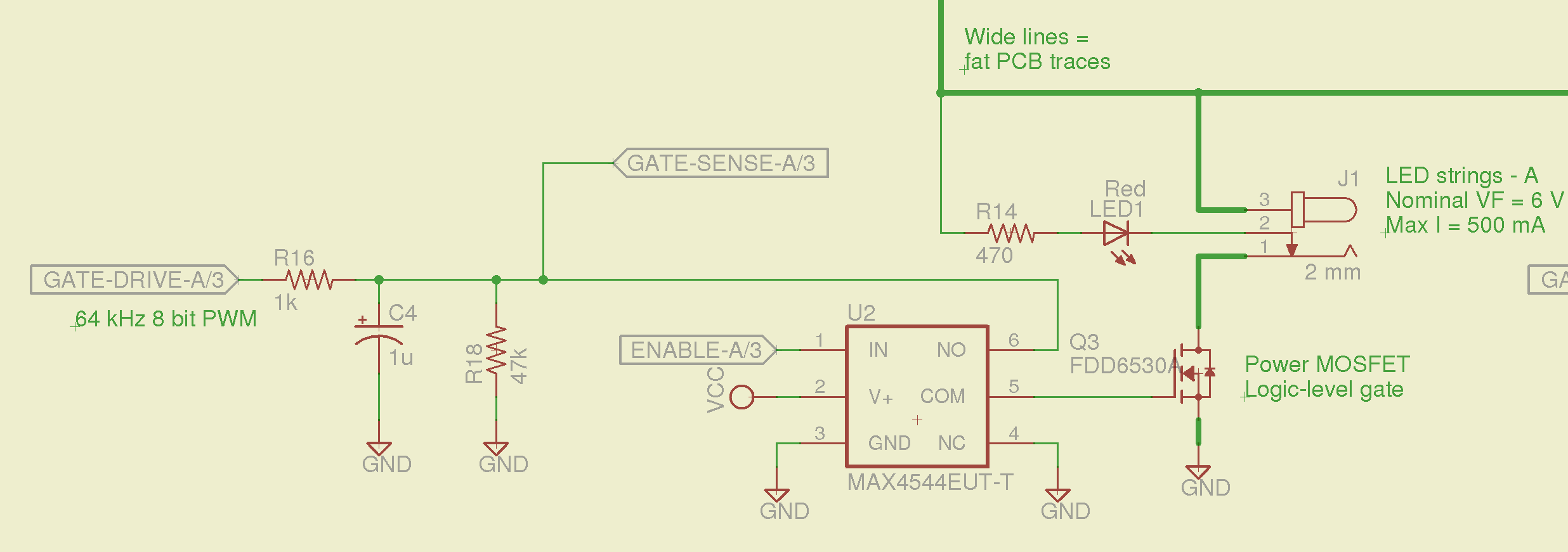
    The crisp rising edge comes from the analog switch between the PWM filter and the MOSFET gate, plus a bit of code trickery that presets the PWM and lets it ramp up before turning on the gate drive.

    I should recompute the voltage-to-current scale factor, but that could rapidly turn into a curve-fitting exercise. It’s pretty close already.

  • Hall Effect LED Current Control: Switched MOSFET Gates

    The rise and fall times for the LEDs on the over-the-top blinky taillight left a bit to be desired, at least if you were interested in short pulses:

    VG 1193 mV - ID 50 mA-div - 1 ms PWM filter - overview
    VG 1193 mV – ID 50 mA-div – 1 ms PWM filter – overview

    So I spliced an analog switch between the PWM filter and the gate, with inputs selecting ground and the PWM drive voltage:

    Switched MOSFET gate - analog switch schematic
    Switched MOSFET gate – analog switch schematic

    This being a prototype, that involved epoxying a SOT23-6 package atop the MOSFET, with flying wires all over the PCB:

    Hall Effect PCB - MOSFET gate switch
    Hall Effect PCB – MOSFET gate switch

    It works pretty well:

    VDS ILED 50 mA div - 200 50 150 25 mA
    VDS ILED 50 mA div – 200 50 150 25 mA

    The top trace is the drain voltage and the bottom trace is the LED current at 50 mA/div.

    The current transitions come out vertical at any sweep speed, even through the Tek Hall effect current probe. The pulses would be rectangular if I weren’t changing the current for each one.

    The current feedback loop closes through the Arduino’s main loop, which includes a 1 ms delay after each PWM output change before measuring the LED current. As a result, each loop takes just under 2 ms, but, fortunately, ramping from 25 mA (in the last pulse) to 200 mA (in the first pulse) requires less than 10 PWM increments; you can see the stairsteps if you squint.

    Next up: bump the PWM to 64 kHz (from 32 kHz) and rip out the pull-down resistor that used to hold the gate near ground when the output floated as an input. That should improve the output ripple caused by the MOSFET’s bias as a perfectly serviceable linear amplifier.

    The control loop now fetches durations & currents from an array-of-structs, so I can customize each pulse. An obvious enhancement: remember the gate drive that produced a given current, then restore the corresponding value as the starting PWM setting for each pulse, so the loop begins closer to reality. The gate drive varies with temperature and suchlike, so it can’t be a compile-time constant, but maybe the startup routine could preload the array / list / cache with values taken from a “lamp test”.

    Four close-together flashes repeating at about 2 Hz, even with two runt pulses, turn the LEDs into a real eye magnet…

  • 3D Printed Things I’ve Designed: Brag Sheets

    The whole reason I got a 3D printer in the first place was to make things that would otherwise be too difficult or tedious by hand or on a CNC mill. Most of the things I make look like brackets and I don’t do sculptures … this stuff solves problems!

    Being able to go from “I need a part shaped like that” to holding the thing in my hand a few hours (or, for complex designs, days) later is empowering. Being able to adjust a dimension by changing the source code and “recompiling” to get a new part is wonderful.

    These five slides from the presentation show my answers to the question “Why would anyone want a 3D printer?” Clicky for more dots.

    Things I Designed - 1
    Things I Designed – 1
    Things I Designed - 2
    Things I Designed – 2
    Things I Designed - 3
    Things I Designed – 3
    Things I Designed - 4
    Things I Designed – 4
    Things I Designed - 5
    Things I Designed – 5

    You can find those and more by searching for OpenSCAD source code.

    They go along with the sheets of solid models.

  • Headband Magnifier: Lamp Switch

    One of my headband magnifiers has a headlight above the brim, an incandescent flashlight bulb powered by a pair of AAA alkaline cells, that hasn’t worked well since the day I bought it. This being a time of finishing small projects, I finally tore it apart and discovered that the cells and contacts were in fine shape (!), the bulb (remember bulbs?) worked, the wiring was OK, but the switch was bad.

    Magnifying headband - lamp switch
    Magnifying headband – lamp switch

    The switch body seems to be firmly anchored in place, so I pried that red base plate off in situ, un-bent the silver-plated (!) spring-contact-actuator, and reassembled it in reverse order. No pictures, as it took less time to do than to tell, but it now works perfectly… most likely, for the first time ever.

    Stop squirming! This can be much more painful…

    Magnifying headband - in action
    Magnifying headband – in action

    I’m mildly tempted to hotwire the guts of a white LED flashlight into the thing, but that would require either another AA cell or a booster circuit and I’m not ready for that just yet.

  • Water Heater Anode Rod Status

    The Whirlpool water heater anode rod is corroding nicely:

    Whirlpool anode rod - 2014-04
    Whirlpool anode rod – 2014-04

    The new GE water heater anode rod seems to be passivating:

    GE anode rod - coated - 2014-04
    GE anode rod – coated – 2014-04

    There’s some corrosion up near the bolt head, so it’s not entirely asleep:

    GE anode rod - bolt - 2014-04
    GE anode rod – bolt – 2014-04

    I hammered the coating off the rod, scuffed the shiny parts with coarse sandpaper, wiped off the dust, and stuck it back in its socket. We’ll see what it looks like next year.

    Both tanks flushed nicely without too much sediment.

    Searching for “water heater” will turn up other posts…

  • Incandescent Bulb Lifetime

    Two 40 W incandescent bulbs in the front bathroom burned out within a few days of each other. Being that type of guy, I know that I installed this bulb nine years ago:

    Bulb base - install date
    Bulb base – install date

    The date is easier to read with the bulb in hand: 13 Feb 05. The (5 yrs) indicates the previous bulb in that socket lasted five years.

    The other bulb date went in during March 09, so it survived only five years; the previous bulb lasted 6 years.

    Even though 40 W incandescent bulbs are history, maybe I have enough spares on the shelf that the next owner can replace ’em with cheap LEDs.

    This may not be science, but it does have numbers…
  • Arduino Knockoff: Cold Solder Joints!

    The knockoff Arduino Pro Mini I used for the strobe photography controller ran the default Blink sketch perfectly, but didn’t respond to its own Reset pushbutton. Probing the Reset line at pin 29 on the microcontroller showed that the pushbutton didn’t pull the +5 V line to ground, so the switch was broken, a trace was broken, or …

    Touching the soldering iron to a switch pin caused the whole thing to pop loose. One glance at the pads tells you something’s badly wrong:

    Arduino Pro Mini Knockoff - cold solder joints
    Arduino Pro Mini Knockoff – cold solder joints

    A closeup, rotated a quarter-turn clockwise:

    Arduino Pro Mini Knockoff - cold solder joint - detail
    Arduino Pro Mini Knockoff – cold solder joint – detail

    That’s the nicest picture of cold solder joints you’ve seen in a while, isn’t it?

    Resoldering the switch solved the problem and, while the iron was hot, I touched all the microcontroller pins, too, just in case