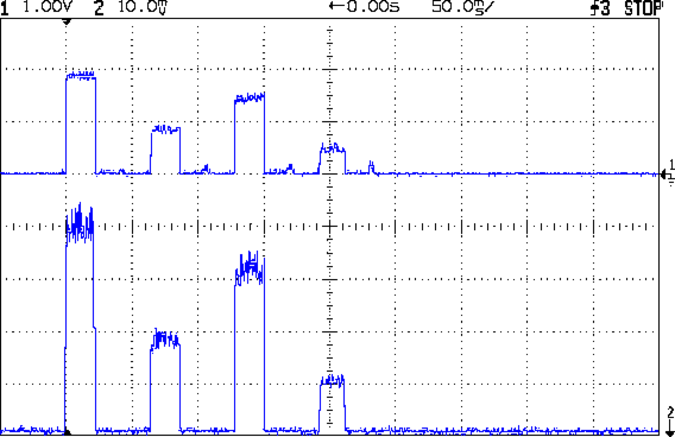
Because the current control loop closes through the Arduino loop(), the code’s path length limits the bandwidth. Worse, the PWM filter imposes a delay while the DC value catches up with the new duty cycle. Here’s what that looks like:

The setpoint current for this pulse is 200 mA, ramping upward from 50 mA. It should have started from 25 mA, but the loop really wasn’t under control here.
The top trace goes low during the drain current measurement, which occurs just before the code nudges the gate drive by 1 PWM count to reduce the error between the setpoint and the measurement. A delay(1) after each PWM change, plus the inherent delay due to all the program statements, produces an update every 1.7 ms, more or less.
Even at that low rate, the current overshoots by 50 mA before the loop can tamp it down again. The current varies by 200 mA for 7 PWM counts, call it 30 mA per count at the high end, so overshooting by 50 mA comes with the territory. There’s just not a lot of resolution available.
The program reads each pulse duration and amplitude from an array-of-structs, so it’s a simple matter of software to save the gate drive voltage at the end of each pulse and restore it when that pulse comes around on the guitar again:
	if (millis() >= (EventStart + (unsigned long)Events[EventIndex].duration)) {
		Events[EventIndex].drive_a = VGateDriveA;						// save drive voltages
		Events[EventIndex].drive_b = VGateDriveB;

        if (++EventIndex > MAX_EVENT_INDEX)								// step to next event
		    EventIndex = 0;

		VGateDriveA = Events[EventIndex].drive_a;						// restore previous drives
		VGateDriveB = Events[EventIndex].drive_b;

		SetPWMVoltage(PIN_SET_VGATE_A,VGateDriveA);
		SetPWMVoltage(PIN_SET_VGATE_B,VGateDriveB);

		delay(PWM_Settle);

		digitalWrite(PIN_ENABLE_A,Events[EventIndex].en_a);				// enable gates for new state
		digitalWrite(PIN_ENABLE_B,Events[EventIndex].en_b);

        NeedHallNull = !(Events[EventIndex].en_a || Events[EventIndex].en_b);	// null sensor if all off

		EventStart = millis();                                          // record start time
	}
… which produces this happy result, with a different time scale to show all four pulses in the array:
The top trace shows the current amp output that goes into the Arduino analog input and the bottom trace shows the MOSFET drain current. Notice those nice, crisp edges with a nearly complete lack of current adjustment.
The small bumps in the amp output just after the LED turns off happen while the the code nulls the Hall effect sensor offset. Whenever the LEDs turn off, the code nulls the sensor, which is probably excessive; it really doesn’t have much else to do, so why not?
This trickery doesn’t improve the loop bandwidth at all, because the code must still drag the current to meet each setpoint, but now that happens only when the pulse first appears. After a few blinks, the current stabilizes at the setpoint and the loop need handle only slight variations due to temperature or battery voltage changes.
Speaking of voltages:

The top trace now shows the MOSFET drain voltage and the bottom still has the LED current. There’s only 650 mV of difference at the drain for currents of 50 mA and 200 mA through the LEDs, with about 1 V of headroom remaining at 200 mA.
The power supply delivers 7.4 V to the anode end of the LEDs, so they drop 6.3 V @ 200 mA and 5.7 V @ 50 mA. Some informal knob twiddling suggests that the MOSFET loses control authority at about 6.5 V, so, given that there’s not much energy in the battery below 7.0 V anyway, the program could limit the maximum current to 50 mA when the battery hits 7 V, regain 650 mV of headroom, and run at reduced brightness (and perhaps a different blink pattern) until the battery drops to 6.5 V, at which point the lights go out.
There’s more improvement to be had in the code, but those pulses look much better.
(If you’re keeping track, as I generally don’t, this is Post Number 2048: love those round numbers!)

Comments
4 responses to “Hall Effect LED Current Control: Crisp Gate Drive Shaping”
Hello, Ed. I haven’t been following your current project too closely, because it is all a little over my head, but I had two questions. What is the advantage of your Hall effect feedback loop over just an open loop PWM version? Given that you have worked out the forward voltage drop on the LEDs, couldn’t you just use a buck/boost regulator and regular PWM? That way you could run the batteries down until the regulator gives out. Secondly, would it be worthwhile to swap the oscillator to run at 20 MHz to get a little bit more resolution?
Please don’t take this as raining on your parade. Your way is certainly more awesome, and I really am curious.
Because LED current depends exponentially on the voltage and inverse-exponentially on the temperature, an open loop voltage source can’t produce a stable current. For example, with the LEDs running at 200 mA, a 20 mV gate voltage change produces a 50 mA current change: 1.6% input variation means 25% output change. That’s the same as having the LED die change by 5 °C, which is much less than when I (inadvertently) measured the die temperature.
Remember that the PWM resolution depends only on the PWM register width, not the counting speed: 8 bits gives you 1/256 resolution. Bumping the CPU clock by 25% is not to be sniffed at, because that reduces the time through the main loop and improves the transient response, but it’s secondary to the crappy eight bits of PWM resolution.
No offense taken!
Straight up: the whole project makes absolutely no sense from a purely economic standpoint, as current-controlled LED drivers are a solved problem that you can buy off the shelf. So are blinky LED bike taillights, for that matter. I’ll even agree it makes little sense from a technical standpoint, but it’s spun off three three years of really interesting & educational sub-projects… and Circuit Cellar columns! [grin]
I gotta do some tech art projects featuring ferrite toroids… they’re not just full-frontal Steampunk, they actually do something.
8 bits? Why not use TIMER1 and get 16 bits?
Every bit of increased resolution means cutting the PWM frequency in half and doubling the ripple current. Reducing the PWM filter bandwidth to compensate means doubling the response time (although, in this case, that’s limited by the main loop iteration time).
It’s all a tradeoff…