Gutting the crystal tester program and grafting a simple joystick interface onto the corpse produces an LF sine wave generator with 0.10 Hz steps:
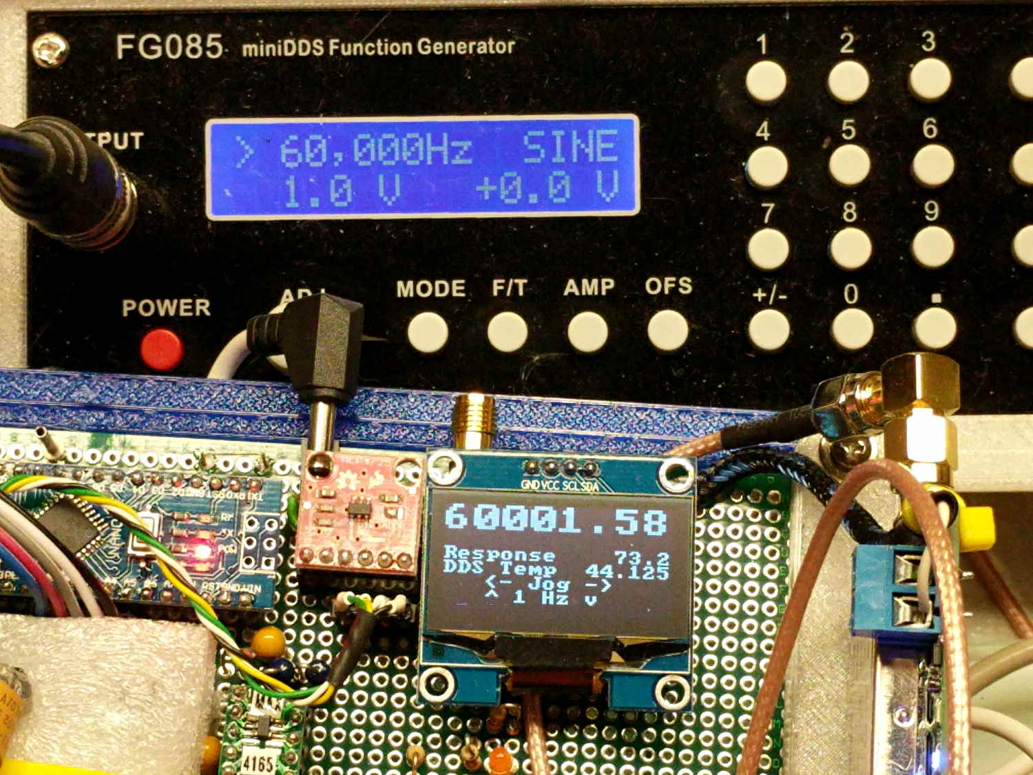
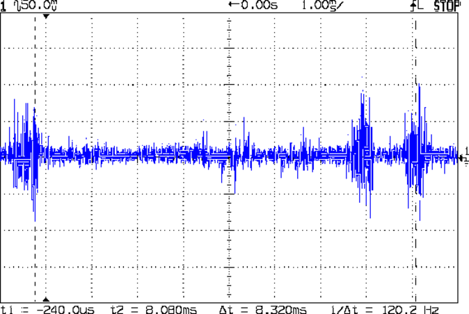
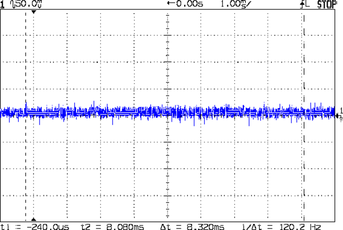
The FG085 function generator shows 60000 Hz and the AD9850 shows 60001.58 Hz, but they’re running at exactly the same frequency:
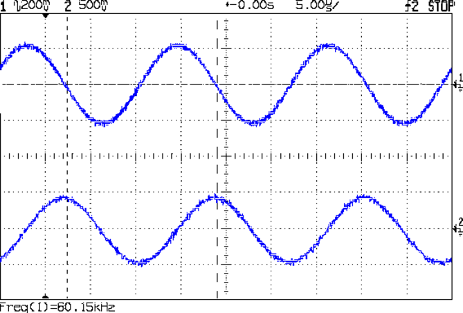
I trust the AD9850 readout, because I just finished zero-beating it against the GPS-locked 10 MHz frequency reference: it’s dead on. The scope’s frequency measurement is clearly out of its depth at this resolution.
The “user interface” doesn’t amount to much. The DDS starts at 60.000 kHz, as defined by a program constant. Push the joystick left-right to step by 0.1 Hz (actually, multiples of 0.0291 Hz, so either 0.087 or 0.116 Hz, whichever makes the answer come out closer to the next multiple of 0.1 Hz). Push it up-down to step by 1.0 Hz (insert similar handwaving here). Push the button inward to reset to 60.000 kHz.
The OLED displays the frequency (in big digits), the output of the log amplifier (which isn’t hooked up here) in dB (over 4 μV), the DDS clock oscillator temperature, and a few lines of static prompting. The camera shutter blanked the last line, which should read “Button = reset”.
There’s no amplitude adjustment, other than the DDS current-control twiddlepot and the buffer amp’s gain-setting jumpers, but I (think I can) gimmick up an adequate inductive kicker for the fake preamp antenna circuit.
Not much to look at, but now I can (manually) probe the frequency response of the 60 kHz preamp with sufficient resolution to figure out if / how the tuning fork resonator filter behaves.
The Arduino source code as a GitHub Gist:
| // Sine wave generator | |
| // Ed Nisley – KE4ZNU | |
| // 2017-09-20 | |
| #include <avr/pgmspace.h> | |
| #include <U8g2lib.h> | |
| #include <U8x8lib.h> | |
| #include <Adafruit_MCP4725.h> | |
| //——————— | |
| // Pin locations | |
| #define PIN_SYNC 5 | |
| #define PIN_CX_SHORT 6 | |
| #define PIN_DDS_RESET 7 | |
| #define PIN_DDS_LATCH 8 | |
| #define PIN_HEARTBEAT 9 | |
| #define PIN_LOG_AMP A0 | |
| #define PIN_JOYBUTTTON A1 | |
| #define PIN_JOY_Y A2 | |
| #define PIN_JOY_X A3 | |
| // SPI & I2C use hardware support: these pins are predetermined | |
| #define PIN_SS 10 | |
| #define PIN_MOSI 11 | |
| #define PIN_MISO 12 | |
| #define PIN_SCK 13 | |
| #define PIN_IIC_SDA A4 | |
| #define PIN_IIC_SCL A5 | |
| // IIC Hardware addresses | |
| // OLED library uses its default address | |
| #define LM75_ADDR 0x48 | |
| #define SH1106_ADDR 0x70 | |
| #define MCP4725_ADDR 0x60 | |
| // Useful constants | |
| #define GIGA 1000000000LL | |
| #define MEGA 1000000LL | |
| #define KILO 1000LL | |
| #define ONE_FX (1LL << 32) | |
| #define CALFREQ (10LL * MEGA * ONE_FX) | |
| // Structures for 64-bit fixed point numbers | |
| // Low word = fractional part | |
| // High word = integer part | |
| struct ll_fx { | |
| uint32_t low; // fractional part | |
| uint32_t high; // integer part | |
| }; | |
| union ll_u { | |
| uint64_t fx_64; | |
| struct ll_fx fx_32; | |
| }; | |
| // Define semi-constant values | |
| union ll_u CenterFreq = {(60000 – 0) * ONE_FX}; // center of scan | |
| //union ll_u CenterFreq = {(32768 – 2) * ONE_FX}; // center of scan | |
| #define NOMINAL_OSC ((125 * MEGA) * ONE_FX) | |
| union ll_u Oscillator = {NOMINAL_OSC}; // oscillator frequency | |
| int16_t OscOffset = 287; // offset from NOMINAL_OSC at room-ish temperature | |
| // Coefficients for oscillator offset as function of temperature | |
| #define TC_SQUARE ((1340 * ONE_FX) / 1000) | |
| #define TC_LINEAR ((-1474 * ONE_FX) / 10) | |
| #define TC_INTERCEPT ((3415 * ONE_FX) ) | |
| // Frequency range & step size | |
| uint16_t TestWidth = 5*2; // width must be an even integer | |
| union ll_u StepSize = {ONE_FX / 10}; // 0.1 Hz is smallest practical decimal step | |
| union ll_u NomFreq, ActualFreq; // displayed vs actual DDS frequency | |
| union ll_u TestFreq; | |
| // Global variables of interest to everyone | |
| union ll_u CtPerHz; // will be 2^32 / oscillator | |
| union ll_u HzPerCt; // will be oscillator / 2^32 | |
| char Buffer[10+1+10+1]; // string buffer for fixed point number conversions | |
| union ll_u Temperature; // read from LM75A | |
| // Hardware library variables | |
| U8X8_SH1106_128X64_NONAME_HW_I2C u8x8(U8X8_PIN_NONE); | |
| //U8X8_SH1106_128X64_NONAME_4W_HW_SPI u8x8(PIN_DISP_SEL, PIN_DISP_DC , PIN_DISP_RST); | |
| //U8X8_SH1106_128X64_NONAME_4W_SW_SPI u8x8(PIN_SCK, PIN_MOSI, PIN_DISP_SEL, PIN_DISP_DC , PIN_DISP_RST); | |
| #define DAC_WR false | |
| #define DAC_WR_EEP true | |
| #define DAC_BITS 12 | |
| #define DAC_MAX 0x0fff | |
| Adafruit_MCP4725 XAxisDAC; // I²C DAC for X axis output | |
| uint32_t XAxisValue; // DAC parameter uses 32 bits | |
| union ll_u LogAmpdB; // computed dB value | |
| // Timekeeping | |
| #define HEARTBEAT_MS 3000 | |
| unsigned long MillisNow,MillisThen; | |
| //———– | |
| // Useful functions | |
| // Pin twiddling | |
| void TogglePin(char bitpin) { | |
| digitalWrite(bitpin,!digitalRead(bitpin)); // toggle the bit based on previous output | |
| } | |
| void PulsePin(char bitpin) { | |
| TogglePin(bitpin); | |
| TogglePin(bitpin); | |
| } | |
| // These may need debouncing in some circuits | |
| void WaitButtonDown() { | |
| word ai; | |
| do { | |
| ai = analogRead(PIN_JOYBUTTTON); | |
| } while (ai > 600); | |
| } | |
| void WaitButtonUp() { | |
| word ai; | |
| do { | |
| ai = analogRead(PIN_JOYBUTTTON); | |
| } while (ai < 400); | |
| } | |
| void WaitButton() { | |
| Serial.print(F("Waiting for button:")); | |
| WaitButtonDown(); | |
| delay(10); | |
| WaitButtonUp(); | |
| delay(100); | |
| Serial.println(F(" done")); | |
| } | |
| // Hardware-assisted SPI I/O | |
| void EnableSPI(void) { | |
| digitalWrite(PIN_SS,HIGH); // set SPI into Master mode | |
| SPCR |= 1 << SPE; | |
| } | |
| void DisableSPI(void) { | |
| SPCR &= ~(1 << SPE); | |
| } | |
| void WaitSPIF(void) { | |
| while (! (SPSR & (1 << SPIF))) { | |
| // TogglePin(PIN_HEARTBEAT); | |
| // TogglePin(PIN_HEARTBEAT); | |
| continue; | |
| } | |
| } | |
| byte SendRecSPI(byte Dbyte) { // send one byte, get another in exchange | |
| SPDR = Dbyte; | |
| WaitSPIF(); | |
| return SPDR; // SPIF will be cleared | |
| } | |
| //————– | |
| // DDS module | |
| void EnableDDS(void) { | |
| digitalWrite(PIN_DDS_LATCH,LOW); // ensure proper startup | |
| digitalWrite(PIN_DDS_RESET,HIGH); // minimum reset pulse 40 ns, not a problem | |
| digitalWrite(PIN_DDS_RESET,LOW); | |
| delayMicroseconds(1); // max latency 100 ns, not a problem | |
| DisableSPI(); // allow manual control of outputs | |
| digitalWrite(PIN_SCK,LOW); // ensure clean SCK pulse | |
| PulsePin(PIN_SCK); // … to latch hardwired config bits | |
| PulsePin(PIN_DDS_LATCH); // load hardwired config bits = begin serial mode | |
| EnableSPI(); // turn on hardware SPI controls | |
| SendRecSPI(0x00); // shift in serial config bits | |
| PulsePin(PIN_DDS_LATCH); // load serial config bits | |
| } | |
| // Write delta phase count to DDS | |
| // This comes from the integer part of a 64-bit scaled value | |
| void WriteDDS(uint32_t DeltaPhase) { | |
| SendRecSPI((byte)DeltaPhase); // low-order byte first | |
| SendRecSPI((byte)(DeltaPhase >> 8)); | |
| SendRecSPI((byte)(DeltaPhase >> 16)); | |
| SendRecSPI((byte)(DeltaPhase >> 24)); | |
| SendRecSPI(0x00); // 5 MSBs = phase = 0, 3 LSBs must be zero | |
| PulsePin(PIN_DDS_LATCH); // write data to DDS | |
| } | |
| //————– | |
| // Log amp module | |
| #define LOG_AMP_SAMPLES 10 | |
| #define LOG_AMP_DELAYMS 10 | |
| uint64_t ReadLogAmp() { | |
| union ll_u LogAmpRaw; | |
| LogAmpRaw.fx_64 = 0; | |
| for (byte i=0; i<LOG_AMP_SAMPLES; i++) { | |
| LogAmpRaw.fx_32.high += analogRead(PIN_LOG_AMP); | |
| delay(LOG_AMP_DELAYMS); | |
| } | |
| LogAmpRaw.fx_64 /= LOG_AMP_SAMPLES; // figure average from totally ad-hoc number of samples | |
| LogAmpRaw.fx_64 *= 5; // convert from ADC counts to voltage at 5 V/1024 counts | |
| LogAmpRaw.fx_64 /= 1024; | |
| LogAmpRaw.fx_64 /= 24; // convert from voltage to dBV at 24 mV/dBV | |
| LogAmpRaw.fx_64 *= 1000; | |
| return LogAmpRaw.fx_64; | |
| } | |
| //———– | |
| // Read LM75A and convert to signed fixed point | |
| // Returns signed value in something otherwise used as unsigned | |
| // Blithely ignores most IIC error conditions | |
| int64_t GetTemperature() { | |
| union ll_u Temp; | |
| Wire.requestFrom(LM75_ADDR,2); | |
| if (Wire.available() == 2) { | |
| Temp.fx_32.high = Wire.read(); | |
| Temp.fx_32.low = (uint32_t)Wire.read() << 24; | |
| if (Temp.fx_32.high & 0x00000080L) { // propagate – sign | |
| Temp.fx_32.high |= 0xffffff00L; | |
| } | |
| } | |
| else { | |
| Temp.fx_64 = 256 * ONE_FX; // in-band error flagging: 256 C | |
| } | |
| return Temp.fx_64; | |
| } | |
| //———– | |
| // Compute frequency offset from oscillator temperature | |
| // This is an ordinary signed integer | |
| // Because 1 Hz resolution at 125 MHz is Good Enough | |
| int16_t ComputeOffset() { | |
| union ll_u Temperature; | |
| union ll_u T1; | |
| Temperature.fx_64 = GetTemperature(); | |
| T1.fx_64 = TC_SQUARE; | |
| if (TC_SQUARE) // skip multiply for linear fit | |
| T1.fx_64 = MultiplyFixedPt(T1,Temperature); | |
| T1.fx_64 += TC_LINEAR; | |
| T1.fx_64 = MultiplyFixedPt(T1,Temperature); | |
| T1.fx_64 += TC_INTERCEPT; | |
| PrintFixedPtRounded(Buffer,Temperature,3); | |
| printf("Offset: %d at %s C\n",(int16_t)T1.fx_32.high,Buffer); | |
| return (int16_t)(T1.fx_32.high); // extract integer part | |
| } | |
| //———– | |
| // Zero-beat oscillator to 10 MHz GPS-locked reference | |
| void ZeroBeat() { | |
| union ll_u TempFreq,TempCount; | |
| printf("Zero beat DDS oscillator against GPS\n"); | |
| TempFreq.fx_64 = CALFREQ; | |
| u8x8.clearDisplay(); | |
| byte ln = 0; | |
| u8x8.drawString(0,ln++,"10 MHz Zero Beat"); | |
| u8x8.drawString(0,ln++," <- Jog -> "); | |
| u8x8.drawString(0,ln++," ^ recalc "); | |
| u8x8.drawString(0,ln++," Button = set "); | |
| int32_t OldOffset = -OscOffset; // ensure first update | |
| while (analogRead(PIN_JOYBUTTTON) > 500) { | |
| TogglePin(PIN_HEARTBEAT); // show we got here | |
| int ai = analogRead(PIN_JOY_Y) – 512; // totally ad-hoc axes | |
| if (ai < -100) { | |
| OscOffset += 1; | |
| } | |
| else if (ai > 100) { | |
| OscOffset -= 1; | |
| } | |
| ai = analogRead(PIN_JOY_X) – 512; | |
| if (ai < -100) { | |
| OscOffset = ComputeOffset(); | |
| } | |
| if (OscOffset != OldOffset) { | |
| ln = 5; | |
| sprintf(Buffer,"Offset %9d",OscOffset); | |
| u8x8.drawString(0,ln,Buffer); | |
| CalcOscillator(OscOffset); // recalculate constants | |
| TempCount.fx_64 = MultiplyFixedPt(TempFreq,CtPerHz); // recalculate delta phase count | |
| WriteDDS(TempCount.fx_32.high); // DDS output should be exactly 10 MHz | |
| OldOffset = OscOffset; | |
| } | |
| Temperature.fx_64 = GetTemperature(); | |
| PrintFixedPtRounded(Buffer,Temperature,3); | |
| ln = 7; | |
| u8x8.drawString(0,ln,"DDS Temp"); | |
| u8x8.drawString(16-strlen(Buffer),ln,Buffer); | |
| delay(100); | |
| } | |
| printf("Oscillator offset: %d at %s C\n",OscOffset,Buffer); | |
| WaitButtonUp(); | |
| u8x8.clearDisplay(); | |
| } | |
| //———– | |
| // Round scaled fixed point to specific number of decimal places: 0 through 8 | |
| // You should display the value with only Decimals characters beyond the point | |
| // Must calculate rounding value as separate variable to avoid mystery error | |
| uint64_t RoundFixedPt(union ll_u TheNumber,unsigned Decimals) { | |
| union ll_u Rnd; | |
| Rnd.fx_64 = (ONE_FX >> 1) / (pow(10LL,Decimals)); // that's 0.5 / number of places | |
| TheNumber.fx_64 = TheNumber.fx_64 + Rnd.fx_64; | |
| return TheNumber.fx_64; | |
| } | |
| //———– | |
| // Multiply two unsigned scaled fixed point numbers without overflowing a 64 bit value | |
| // Perforce, the product of the two integer parts mut be < 2^32 | |
| uint64_t MultiplyFixedPt(union ll_u Mcand, union ll_u Mplier) { | |
| union ll_u Result; | |
| Result.fx_64 = ((uint64_t)Mcand.fx_32.high * (uint64_t)Mplier.fx_32.high) << 32; // integer parts (clear fract) | |
| Result.fx_64 += ((uint64_t)Mcand.fx_32.low * (uint64_t)Mplier.fx_32.low) >> 32; // fraction parts (always < 1) | |
| Result.fx_64 += (uint64_t)Mcand.fx_32.high * (uint64_t)Mplier.fx_32.low; // cross products | |
| Result.fx_64 += (uint64_t)Mcand.fx_32.low * (uint64_t)Mplier.fx_32.high; | |
| return Result.fx_64; | |
| } | |
| //———– | |
| // Long long print-to-buffer helpers | |
| // Assumes little-Endian layout | |
| void PrintHexLL(char *pBuffer,union ll_u FixedPt) { | |
| sprintf(pBuffer,"%08lx %08lx",FixedPt.fx_32.high,FixedPt.fx_32.low); | |
| } | |
| // converts all 9 decimal digits of fraction, which should suffice | |
| void PrintFractionLL(char *pBuffer,union ll_u FixedPt) { | |
| union ll_u Fraction; | |
| Fraction.fx_64 = FixedPt.fx_32.low; // copy 32 fraction bits, high order = 0 | |
| Fraction.fx_64 *= GIGA; // times 10^9 for conversion | |
| Fraction.fx_64 >>= 32; // align integer part in low long | |
| sprintf(pBuffer,"%09lu",Fraction.fx_32.low); // convert low long to decimal | |
| } | |
| void PrintIntegerLL(char *pBuffer,union ll_u FixedPt) { | |
| sprintf(pBuffer,"%lu",FixedPt.fx_32.high); | |
| } | |
| void PrintFixedPt(char *pBuffer,union ll_u FixedPt) { | |
| PrintIntegerLL(pBuffer,FixedPt); // do the integer part | |
| pBuffer += strlen(pBuffer); // aim pointer beyond integer | |
| *pBuffer++ = '.'; // drop in the decimal point, tick pointer | |
| PrintFractionLL(pBuffer,FixedPt); | |
| } | |
| void PrintFixedPtRounded(char *pBuffer,union ll_u FixedPt,unsigned Decimals) { | |
| char *pDecPt; | |
| FixedPt.fx_64 = RoundFixedPt(FixedPt,Decimals); | |
| PrintIntegerLL(pBuffer,FixedPt); // do the integer part | |
| pBuffer += strlen(pBuffer); // aim pointer beyond integer | |
| pDecPt = pBuffer; // save the point location | |
| *pBuffer++ = '.'; // drop in the decimal point, tick pointer | |
| PrintFractionLL(pBuffer,FixedPt); // do the fraction | |
| if (Decimals == 0) | |
| *pDecPt = 0; // 0 places means discard the decimal point | |
| else | |
| *(pDecPt + Decimals + 1) = 0; // truncate string to leave . and Decimals chars | |
| } | |
| //———– | |
| // Calculate useful "constants" from oscillator info | |
| void CalcOscillator(int16_t Offset) { | |
| Oscillator.fx_64 = NOMINAL_OSC + (Offset * ONE_FX); // offset may be negative, It Just Works | |
| HzPerCt.fx_32.low = Oscillator.fx_32.high; // divide oscillator by 2^32 with simple shifting | |
| HzPerCt.fx_32.high = 0; | |
| CtPerHz.fx_64 = -1; // Compute (2^32 – 1) / oscillator | |
| CtPerHz.fx_64 /= (uint64_t)Oscillator.fx_32.high; // remove 2^32 scale factor from divisor | |
| } | |
| //———– | |
| //– Helper routine for printf() | |
| int s_putc(char c, FILE *t) { | |
| Serial.write(c); | |
| } | |
| //———– | |
| void setup () { | |
| union ll_u TempFreq,TempCount; | |
| pinMode(PIN_HEARTBEAT,OUTPUT); | |
| digitalWrite(PIN_HEARTBEAT,LOW); // show we got here | |
| pinMode(PIN_SYNC,OUTPUT); | |
| digitalWrite(PIN_SYNC,LOW); | |
| Serial.begin (115200); | |
| fdevopen(&s_putc,0); // set up serial output for printf() | |
| Serial.println (F("60 kHz Sine Generator")); | |
| Serial.println (F("Ed Nisley – KE4ZNU – September 2017\n")); | |
| // DDS module controls | |
| pinMode(PIN_DDS_LATCH,OUTPUT); | |
| digitalWrite(PIN_DDS_LATCH,LOW); | |
| pinMode(PIN_DDS_RESET,OUTPUT); | |
| digitalWrite(PIN_DDS_RESET,HIGH); | |
| // Light up the display | |
| Serial.println("Initialize OLED"); | |
| u8x8.begin(); | |
| u8x8.setFont(u8x8_font_artossans8_r); | |
| // u8x8.setPowerSave(0); | |
| u8x8.setFont(u8x8_font_pxplusibmcga_f); | |
| u8x8.draw2x2String(0,0,"Sine Gen"); | |
| u8x8.drawString(0,3,"Ed Nisley"); | |
| u8x8.drawString(0,4," KE4ZNU"); | |
| u8x8.drawString(0,5,"2017-09-20"); | |
| u8x8.drawString(0,6,"Press Button …"); | |
| // configure SPI hardware | |
| pinMode(PIN_SS,OUTPUT); // set up manual controls | |
| digitalWrite(PIN_SS,HIGH); | |
| pinMode(PIN_SCK,OUTPUT); | |
| digitalWrite(PIN_SCK,LOW); | |
| pinMode(PIN_MOSI,OUTPUT); | |
| digitalWrite(PIN_MOSI,LOW); | |
| pinMode(PIN_MISO,INPUT_PULLUP); | |
| SPCR = B00110000; // Auto SPI: no int, disabled, LSB first, master, + edge, leading, f/4 | |
| SPSR = B00000000; // not double data rate | |
| TogglePin(PIN_HEARTBEAT); // show we got here | |
| // Set up X axis DAC output | |
| XAxisDAC.begin(MCP4725_ADDR); // start up MCP4725 DAC at Sparkfun address | |
| // XAxisDAC.setVoltage(0,DAC_WR_EEP); // do this once per DAC to set power-on at 0 V | |
| XAxisDAC.setVoltage(0,DAC_WR); // force 0 V after a reset without a power cycle | |
| // LM75A temperature sensor requires no setup! | |
| // External capacitor in test fixture | |
| // Turn relay off to keep the heat down | |
| pinMode(PIN_CX_SHORT,OUTPUT); | |
| digitalWrite(PIN_CX_SHORT,LOW); | |
| // Frequencies | |
| PrintFixedPtRounded(Buffer,CenterFreq,1); | |
| printf("Center freq: %s Hz\n",Buffer); | |
| NomFreq = CenterFreq; | |
| // Wake up and load the DDS | |
| OscOffset = ComputeOffset(); | |
| CalcOscillator(OscOffset); | |
| Serial.print("\nStarting DDS: "); | |
| TempFreq.fx_64 = CALFREQ; | |
| TempCount.fx_64 = MultiplyFixedPt(TempFreq,CtPerHz); | |
| EnableDDS(); | |
| WriteDDS(TempCount.fx_32.high); | |
| Serial.println("running\n"); | |
| WaitButton(); // pause until button release | |
| u8x8.setPowerSave(0); | |
| u8x8.clearDisplay(); | |
| Serial.println("\nStartup done\n"); | |
| MillisThen = millis(); | |
| ZeroBeat(); // compensate for oscillator clock offset | |
| TempCount.fx_64 = MultiplyFixedPt(NomFreq,CtPerHz); // set up initial frequency | |
| WriteDDS(TempCount.fx_32.high); | |
| u8x8.drawString(0,5," <- Jog -> "); | |
| u8x8.drawString(0,6," ^ 1 Hz v "); | |
| u8x8.drawString(0,7," Button = reset "); | |
| } | |
| //———– | |
| void loop () { | |
| byte ln; | |
| union ll_u DDSCount; | |
| TestFreq = NomFreq; // assume no change | |
| if (analogRead(PIN_JOYBUTTTON) > 500) { // button unpushed? | |
| int ai = analogRead(PIN_JOY_Y) – 512; // X axis = left-right | |
| if (ai < -100) | |
| TestFreq.fx_64 = NomFreq.fx_64 + StepSize.fx_64; | |
| else if (ai > 100) | |
| TestFreq.fx_64 = NomFreq.fx_64 – StepSize.fx_64; | |
| else { | |
| ai = analogRead(PIN_JOY_X) – 512; // Y axis = up-down | |
| if (ai < -100) | |
| TestFreq.fx_64 = NomFreq.fx_64 + ONE_FX; | |
| else if (ai > 100) | |
| TestFreq.fx_64 = NomFreq.fx_64 – ONE_FX; | |
| } | |
| } | |
| else | |
| TestFreq = CenterFreq; // reset on button push | |
| DDSCount.fx_64 = MultiplyFixedPt(TestFreq,CtPerHz); // compute DDS delta phase | |
| DDSCount.fx_32.low = 0; // truncate count to integer | |
| ActualFreq.fx_64 = MultiplyFixedPt(DDSCount,HzPerCt); | |
| if (TestFreq.fx_64 != NomFreq.fx_64) { // avoid writing same value | |
| WriteDDS(DDSCount.fx_32.high); | |
| NomFreq = TestFreq; // set up new value | |
| } | |
| ln = 0; | |
| PrintFixedPtRounded(Buffer,ActualFreq,2); // display actual frequency | |
| u8x8.draw2x2String(0,ln,Buffer); | |
| ln = 3; | |
| LogAmpdB.fx_64 = ReadLogAmp(); // show current response | |
| PrintFixedPtRounded(Buffer,LogAmpdB,1); | |
| u8x8.drawString(0,ln,"Response"); | |
| u8x8.drawString(16-strlen(Buffer),ln++,Buffer); | |
| Temperature.fx_64 = GetTemperature(); // and temperature | |
| PrintFixedPtRounded(Buffer,Temperature,3); | |
| u8x8.drawString(0,ln,"DDS Temp"); | |
| u8x8.drawString(16-strlen(Buffer),ln++,Buffer); | |
| delay(100); | |
| } | |