Limiting the resonator drive to about 1 μW in the face of wildly varying RF from the antenna (or the occasional finger fumble) requires brute force. A nose-to-tail pair of Schottky diodes seems to do the trick:
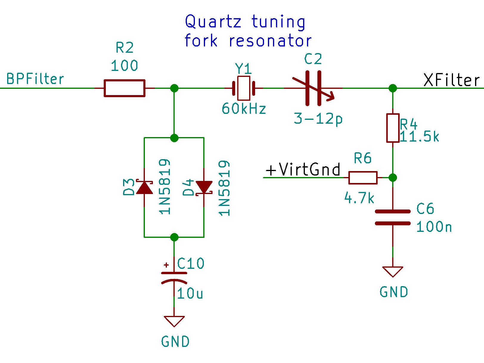
The 100 Ω resistor blunts the drive from the LM353 op amp (implementing a bandpass filter) when the signal peaks exceed 200-ish mV in either direction from the Vcc/2 bias stored in the 10 μF cap.
The 11.5 kΩ resistor downstream of the resonator isolates it from the Vcc/2 bias, with the 100 nF cap sinkholing the signal and the 4.7 kΩ resistor preventing feedback into the bias supply. The cap looks like 26 Ω at 60 kHz, so the feedback runs -52 dB from the output and the bias supply knocks it down a bit more. The preceding amps apply 40-ish dB of gain from the antenna terminals, so the loop gain looks OK.
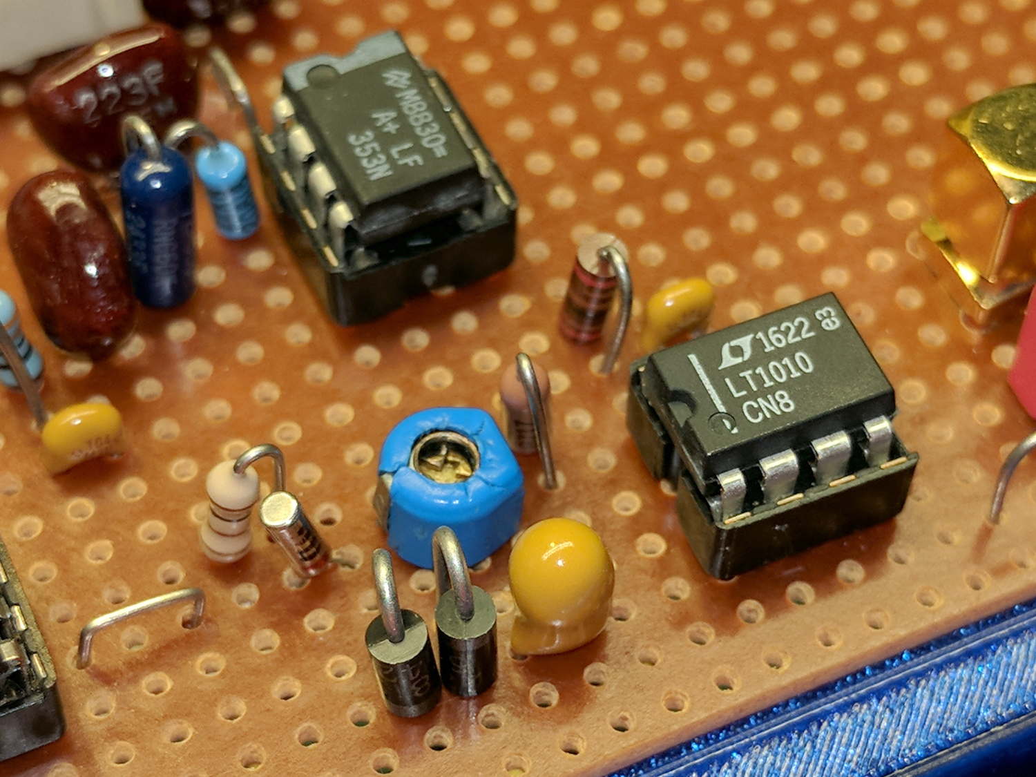
It’s another few components on the board:
The blue twiddlecap should allow pulling the tuning fork’s series resonance upward to exactly 60 kHz.
Applying way too much signal to the antenna terminals in order to get 1 Vpp from the LM353 shows the limiter in action:
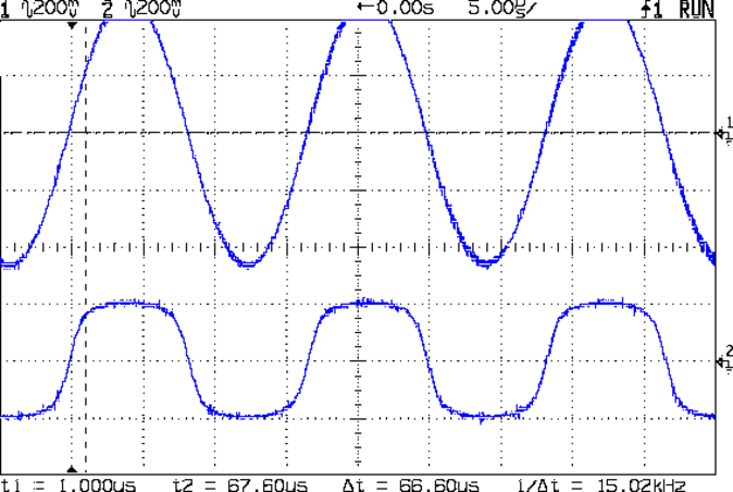
The resonator sees no more than 200 mV in either direction from the bias level, so it’s all good.
On the low end, the diodes have no effect:
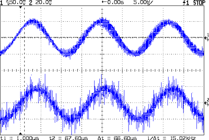
Pay no attention to all that noise.
My first thought was to put the diodes across the resonator, a Bad Idea: straight up, doesn’t work. The 1N5819 datasheet shows they have about 300 pF of junction capacitance at zero bias and a pair of ’em will swamp the resonator’s internal 0.8 pF parallel capacitance and punch it out of the circuit.

Comments
2 responses to “60 kHz Preamp: Tuning Fork Resonator Protection”
[…] the frequency response of the 60 kHz preamp with sufficient resolution to figure out if / how the tuning fork resonator filter […]
[…] similar cap rebiases the protected resonator at the LT1010 buffer […]