We spotted this upgrade on a recent trip to a Powerhouse Theater production:
Compared with the older version, I’d say it’s a great improvement:
Who says things never get better?
The Smell of Molten Projects in the Morning
Ed Nisley's Blog: Shop notes, electronics, firmware, machinery, 3D printing, laser cuttery, and curiosities. Contents: 100% human thinking, 0% AI slop.
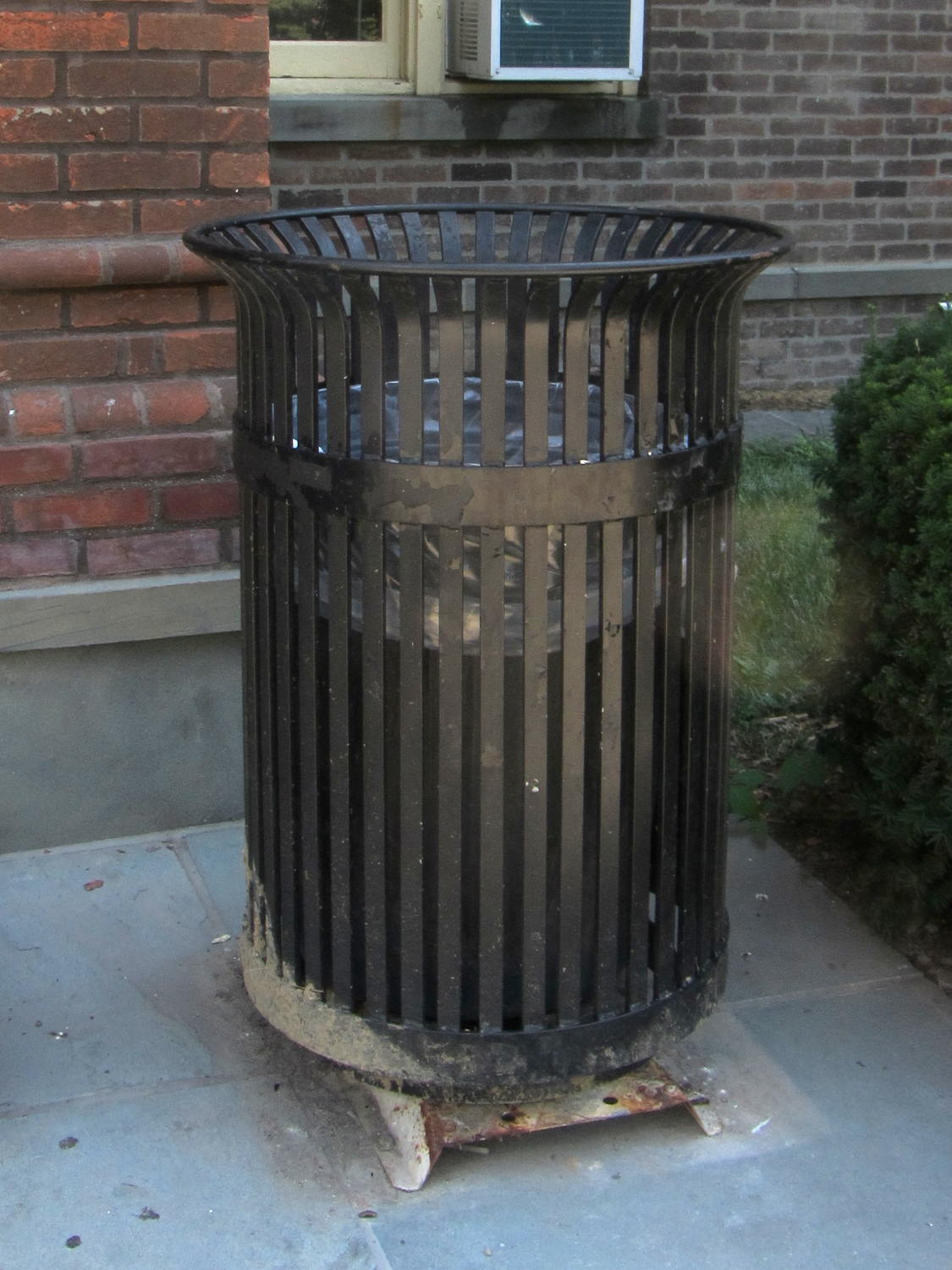
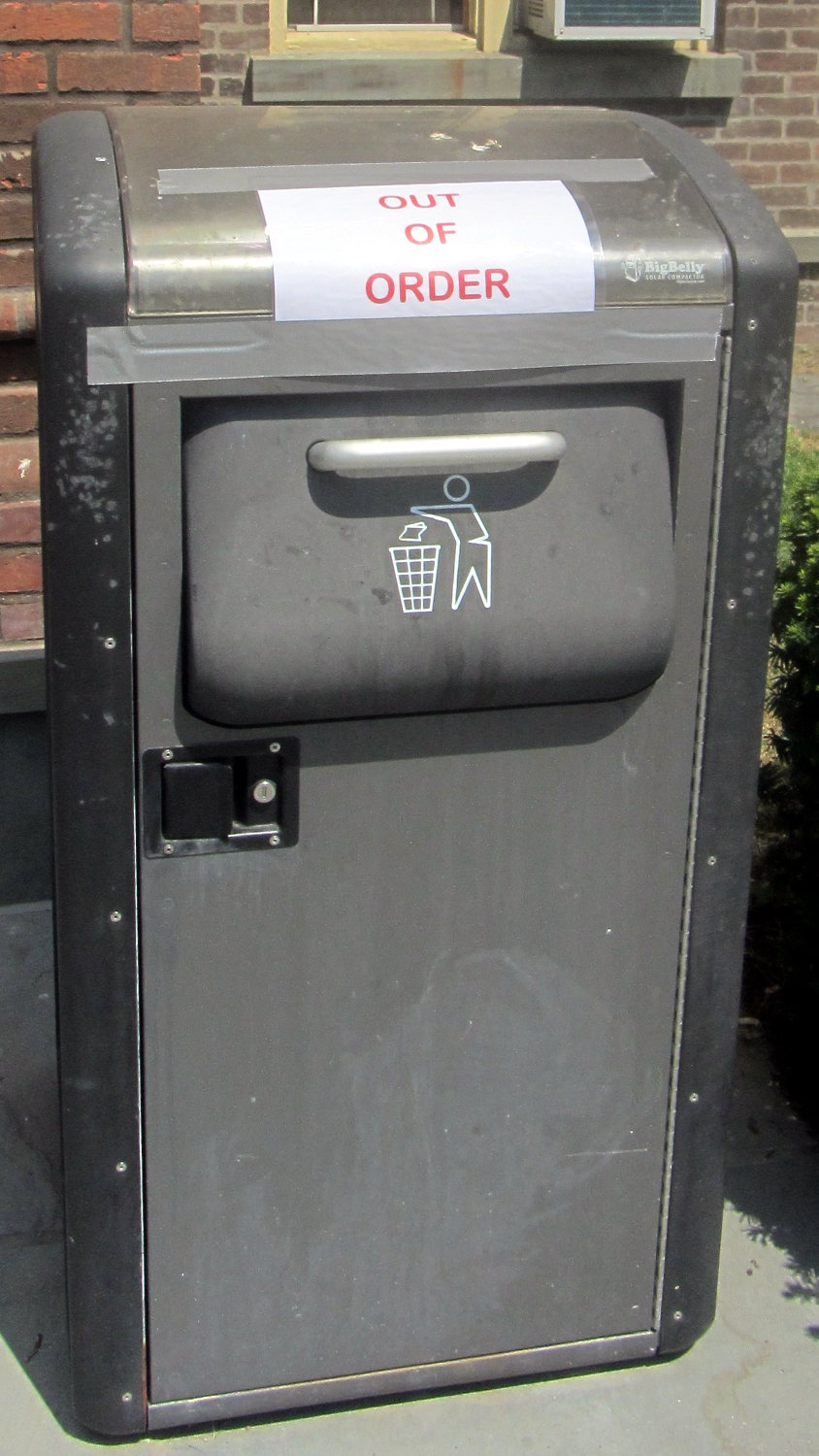
We spotted this upgrade on a recent trip to a Powerhouse Theater production:
Compared with the older version, I’d say it’s a great improvement:
Who says things never get better?
This truck’s home base seems to be south of Maloney on Rt 376 and it occasionally passes me on the road:

My eye-blink reaction that it was a junker turns out to be completely wrong, as it sports a really great paint job (vinyl wrap?):

The junker aspect may not be quite what they expected…
I’m not sure that’s skeuomorphic, but I don’t know the proper term.
I generally ride somewhat further into the travel lane than some folks would prefer, but I have good reason for that. Here’s how bicycling along Raymond Avenue at 14 mph = 20 ft/s on a pleasant summer morning works out…
T = 0.000 — Notice anything out of the ordinary?

T = 1.000 — Me, neither:

T = 1.500 — Ah!

T = 2.000 — I’m flinching into the right turn required for a sharp left turn:

Less than half a second reaction time: pretty good, sez me.
T = 2.833 — End of the flinch:

T = 3.000 — Now I can lean and turn left:

T = 3.267 — This better be far enough left:

T = 3.333 — The door isn’t moving:

T = 3.567 — So I’ll live to ride another day:

I carry a spectacular scar from slashing my arm on a frameless car window, back in my college days: the driver flipped the door open as I passed his gas cap at a good clip. The collision wrecked the window, the door, and my bike, but didn’t break my arm, sever any nerves, or cut any arteries. I did discover human fatty tissue, neatly scooped from under my arm onto the window, is yellowish, which wasn’t something I needed to know.
Searching for Raymond Avenue will bring up other examples of bicycle-hostile features along this stretch of NYSDOT’s trendy, traffic-calmed design…
A discussion over the Squidwrench Operating Table about injecting entropy into VMs before / during their boot sequence reminded me that I wanted to try the Entropy library with my 8×8 RGB LED matrix:

The original version trundled along with random numbers produced by timing Geiger counter ticks. The second version, digitizing the amplified noise from a reverse-biased PN junction, ran much faster.
What’s new & different: the Entropy library measures the jitter between the ATmega328 watchdog timer’s RC oscillator and the ceramic resonator (on Pro Mini boards) driving the CPU. It cranks out four bytes of uncorrelated bits every half-second, which isn’t quite fast enough for a sparkly display, but re-seeding the Arduino PRNG whenever enough entropy arrives works well enough.
One could, of course, re-seed the PRNG with Geiger bits or junction noise to the same effect. The key advantage of the Entropy library: no external hardware required. The downside: no external hardware required, so, minus those techie transistors / resistors / op amps, it will look like Just Another Arduino Project.

Le sigh.
In any event, the Entropy library has excellent documentation and works perfectly.
The Arduino PRNG can produce results fast enough for wonderfully twinkly output that’s visually indistinguishable from the “true” random numbers from the Geiger counter or PN junction. I dialed it back to one update every 5 ms, because letting it free-run turned the display into an unattractive blur.
The top trace shows the update actually happens every 6 ms:

The lower trace shows that each matrix row refresh takes about a millisecond. Refreshes occur on every main loop iteration and interfere with the update, not that that makes any difference. Should it matter, subtract one from the update period and it’ll be all good.
The Arduino source code as a GitHub Gist:
| // Random LED Dots | |
| // Based on Entropy library using watchdog timer jitter | |
| // https://sites.google.com/site/astudyofentropy/project-definition/timer-jitter-entropy-sources/entropy-library | |
| // Ed Nisley – KE4ANU – August 2016 | |
| #include <Entropy.h> | |
| //———- | |
| // Pin assignments | |
| const byte PIN_HEARTBEAT = 8; // DO – heartbeat LED | |
| const byte PIN_SYNC = A3; // DO – scope sync | |
| const byte PIN_LATCH = 4; // DO – shift register latch clock | |
| const byte PIN_DIMMING = 9; // AO – LED dimming control | |
| // These are *hardware* SPI pins | |
| const byte PIN_MOSI = 11; // DO – data to shift reg | |
| const byte PIN_MISO = 12; // DI – data from shift reg (unused) | |
| const byte PIN_SCK = 13; // DO – shift clock to shift reg (also Arduino LED) | |
| const byte PIN_SS = 10; // DO – -slave select (must be positive for SPI output) | |
| //———- | |
| // Constants | |
| #define UPDATE_MS 5 | |
| //———- | |
| // Globals | |
| // LED selects are high-active bits and low-active signals: flipped in UpdateLEDs() | |
| // *exactly* one row select must be active in each element | |
| typedef struct { | |
| const byte Row; | |
| byte ColR; | |
| byte ColG; | |
| byte ColB; | |
| } LED_BYTES; | |
| // altering the number of rows & columns will require substantial code changes… | |
| #define NUMROWS 8 | |
| #define NUMCOLS 8 | |
| LED_BYTES LEDs[NUMROWS] = { | |
| {0x80,0,0,0}, | |
| {0x40,0,0,0}, | |
| {0x20,0,0,0}, | |
| {0x10,0,0,0}, | |
| {0x08,0,0,0}, | |
| {0x04,0,0,0}, | |
| {0x02,0,0,0}, | |
| {0x01,0,0,0}, | |
| }; | |
| byte RowIndex; | |
| #define LEDS_ON 0 | |
| #define LEDS_OFF 255 | |
| unsigned long MillisNow; | |
| unsigned long MillisThen; | |
| //– Helper routine for printf() | |
| int s_putc(char c, FILE *t) { | |
| Serial.write(c); | |
| } | |
| //– Useful stuff | |
| // Free RAM space monitor | |
| // From http://playground.arduino.cc/Code/AvailableMemory | |
| uint8_t * heapptr, * stackptr; | |
| void check_mem() { | |
| stackptr = (uint8_t *)malloc(4); // use stackptr temporarily | |
| heapptr = stackptr; // save value of heap pointer | |
| free(stackptr); // free up the memory again (sets stackptr to 0) | |
| stackptr = (uint8_t *)(SP); // save value of stack pointer | |
| } | |
| void TogglePin(char bitpin) { | |
| digitalWrite(bitpin,!digitalRead(bitpin)); // toggle the bit based on previous output | |
| } | |
| void PulsePin(char bitpin) { | |
| TogglePin(bitpin); | |
| TogglePin(bitpin); | |
| } | |
| //——— | |
| //– SPI utilities | |
| void EnableSPI(void) { | |
| digitalWrite(PIN_SS,HIGH); // make sure this is high! | |
| SPCR |= 1 << SPE; | |
| } | |
| void DisableSPI(void) { | |
| SPCR &= ~(1 << SPE); | |
| } | |
| void WaitSPIF(void) { | |
| while (! (SPSR & (1 << SPIF))) { | |
| // TogglePin(PIN_HEARTBEAT); | |
| continue; | |
| } | |
| } | |
| byte SendRecSPI(byte Dbyte) { // send one byte, get another in exchange | |
| SPDR = Dbyte; | |
| WaitSPIF(); | |
| return SPDR; // SPIF will be cleared | |
| } | |
| void UpdateLEDs(byte i) { | |
| SendRecSPI(~LEDs[i].ColB); // low-active outputs | |
| SendRecSPI(~LEDs[i].ColG); | |
| SendRecSPI(~LEDs[i].ColR); | |
| SendRecSPI(~LEDs[i].Row); | |
| analogWrite(PIN_DIMMING,LEDS_OFF); // turn off LED to quench current | |
| PulsePin(PIN_LATCH); // make new shift reg contents visible | |
| analogWrite(PIN_DIMMING,LEDS_ON); | |
| } | |
| //————— | |
| // Set LED from integer | |
| // On average, this leaves the LED unchanged for 1/8 of the calls… | |
| void SetLED(unsigned long Value) { | |
| byte Row = Value & 0x07; | |
| byte Col = (Value >> 3) & 0x07; | |
| byte Color = (Value >> 6) & 0x07; | |
| byte BitMask = (0x80 >> Col); | |
| // printf("%u %u %u %u\r\n",Row,Col,Color,BitMask); | |
| LEDs[Row].ColR &= ~BitMask; | |
| LEDs[Row].ColR |= (Color & 0x04) ? BitMask : 0; | |
| LEDs[Row].ColG &= ~BitMask; | |
| LEDs[Row].ColG |= (Color & 0x02) ? BitMask : 0; | |
| LEDs[Row].ColB &= ~BitMask; | |
| LEDs[Row].ColB |= (Color & 0x01) ? BitMask : 0; | |
| } | |
| //—————— | |
| // Set things up | |
| void setup() { | |
| pinMode(PIN_HEARTBEAT,OUTPUT); | |
| digitalWrite(PIN_HEARTBEAT,HIGH); // show we arrived | |
| pinMode(PIN_SYNC,OUTPUT); | |
| digitalWrite(PIN_SYNC,LOW); | |
| pinMode(PIN_MOSI,OUTPUT); // SPI-as-output is not strictly necessary | |
| digitalWrite(PIN_MOSI,LOW); | |
| pinMode(PIN_SCK,OUTPUT); | |
| digitalWrite(PIN_SCK,LOW); | |
| pinMode(PIN_SS,OUTPUT); | |
| digitalWrite(PIN_SS,HIGH); // OUTPUT + HIGH is required to make SPI output work | |
| pinMode(PIN_LATCH,OUTPUT); | |
| digitalWrite(PIN_LATCH,LOW); | |
| Serial.begin(57600); | |
| fdevopen(&s_putc,0); // set up serial output for printf() | |
| printf("Random LED Dots – Watchdog Entropy\r\nEd Nisley – KE4ZNU – August 2016\r\n"); | |
| Entropy.initialize(); // start up entropy collector | |
| //– Set up SPI hardware | |
| SPCR = B01110001; // Auto SPI: no int, enable, LSB first, master, + edge, leading, f/16 | |
| SPSR = B00000000; // not double data rate | |
| EnableSPI(); // turn on the SPI hardware | |
| SendRecSPI(0); // set valid data in shift registers: select Row 0, all LEDs off | |
| //– Dimming pin must use fast PWM to avoid beat flicker with LED refresh rate | |
| // Timer 1: PWM 9 PWM 10 | |
| analogWrite(PIN_DIMMING,LEDS_OFF); // disable column drive (hardware pulled it low before startup) | |
| TCCR1A = B10000001; // Mode 5 = fast 8-bit PWM with TOP=FF | |
| TCCR1B = B00001001; // … WGM, 1:1 clock scale -> 64 kHz | |
| //– lamp test: send a white flash through all LEDs | |
| printf("Lamp test begins: white flash each LED…"); | |
| digitalWrite(PIN_HEARTBEAT,LOW); // turn off while panel blinks | |
| analogWrite(PIN_DIMMING,LEDS_ON); // enable column drive | |
| for (byte i=0; i<NUMROWS; i++) { | |
| for (byte j=0; j<NUMCOLS; j++) { | |
| LEDs[i].ColR = LEDs[i].ColG = LEDs[i].ColB = 0x80 >> j; | |
| for (byte k=0; k<NUMROWS; k++) { | |
| UpdateLEDs(k); | |
| delay(25); | |
| } | |
| LEDs[i].ColR = LEDs[i].ColG = LEDs[i].ColB = 0; | |
| } | |
| } | |
| UpdateLEDs(NUMROWS-1); // clear the last LED | |
| printf(" done!\r\n"); | |
| //– Preload LEDs with random values | |
| digitalWrite(PIN_HEARTBEAT,LOW); | |
| uint32_t rn = Entropy.random(); | |
| printf("Preloading LED array with seed: %08lx\r\n",rn); | |
| randomSeed(rn); | |
| for (byte Row=0; Row<NUMROWS; Row++) { | |
| for (byte Col=0; Col<NUMCOLS; Col++) { // Col runs backwards, but we don't care | |
| LEDs[Row].ColR |= random(2) << Col; // random(2) returns 0 or 1 | |
| LEDs[Row].ColG |= random(2) << Col; | |
| LEDs[Row].ColB |= random(2) << Col; | |
| } | |
| UpdateLEDs(Row); | |
| } | |
| check_mem(); | |
| printf("SP: %u HP: %u Free RAM: %u\r\n",stackptr,heapptr,stackptr – heapptr); | |
| printf("Running…\r\n"); | |
| MillisThen = millis(); | |
| } | |
| //—————— | |
| // Run the test loop | |
| void loop() { | |
| unsigned long Hash; | |
| uint32_t rn; | |
| MillisNow = millis(); | |
| // Re-seed the generator whenever we get enough entropy | |
| if (Entropy.available()) { | |
| digitalWrite(PIN_HEARTBEAT,HIGH); | |
| rn = Entropy.random(); | |
| // printf("Random: %08lx ",rn); | |
| randomSeed(rn); | |
| digitalWrite(PIN_HEARTBEAT,LOW); | |
| } | |
| // If it's time for a change, whack a random LED | |
| if ((MillisNow – MillisThen) > UPDATE_MS) { | |
| MillisThen = MillisNow; | |
| SetLED(random()); | |
| } | |
| // Refresh LED array to maintain the illusion of constant light | |
| UpdateLEDs(RowIndex++); | |
| if (RowIndex >= NUMROWS) { | |
| RowIndex = 0; | |
| PulsePin(PIN_SYNC); | |
| } | |
| } | |
I picked up a horsehair dust brush from eBay as a lightweight substitute for the Electrolux aluminum ball, discovered that an adapter I’d already made fit perfectly, did the happy dance, and printed one for the brush. That worked perfectly for half a year, whereupon:

It broke about where I expected, along the layer lines at the cross section where the snout joins the fitting. You can see the three perimeter shells I hoped would strengthen the part:
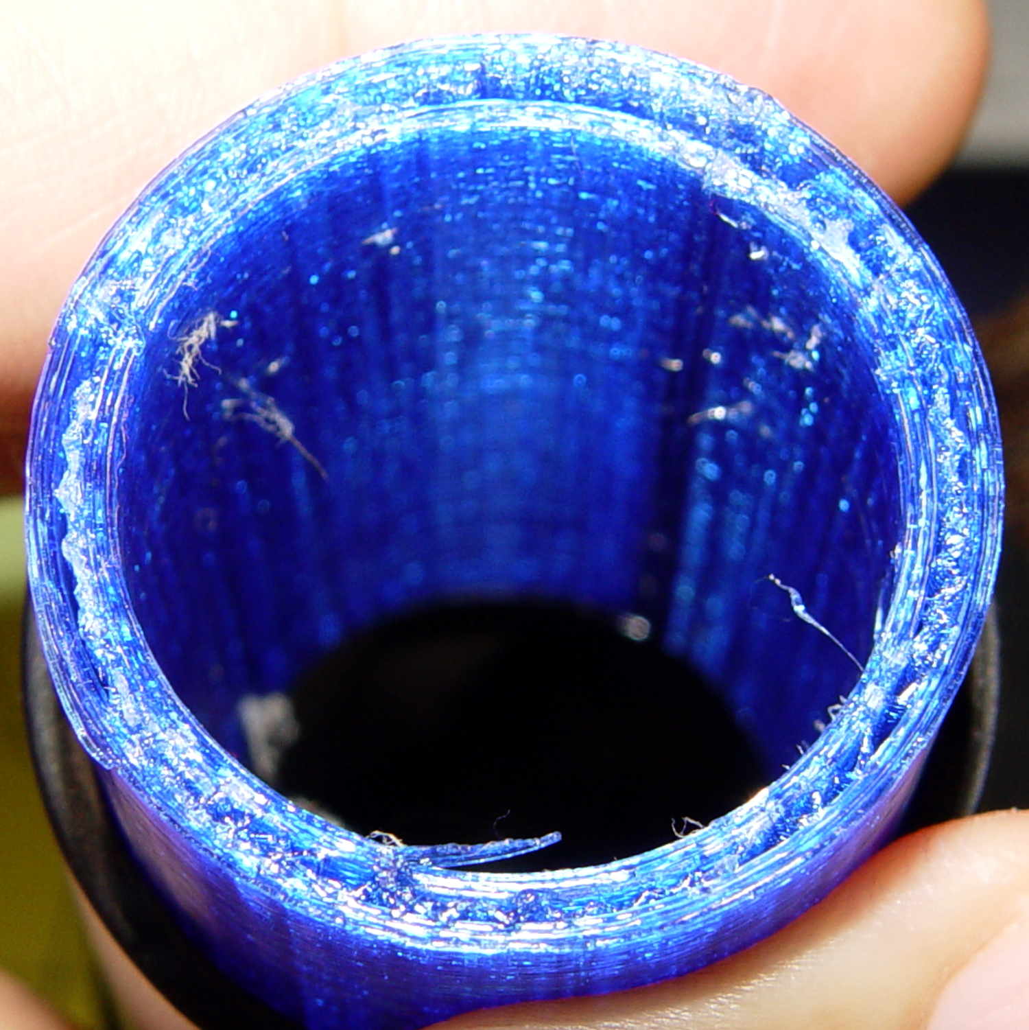
That has the usual 15% 3D Honeycomb infill, although there’s not a lot area for infill.
There’s obviously a stress concentration there and making the wall somewhat thicker (to get more plastic-to-plastic area) might suffice. I’m not convinced the layer bonding would be good enough, even with more wall area, to resist the stress; that’s pretty much a textbook example of how & where 3D printed parts fail.
That cross section should look like this:

Anyhow, I buttered the snout’s broken end with JB Kwik epoxy, aligned the parts, and clamped them overnight:
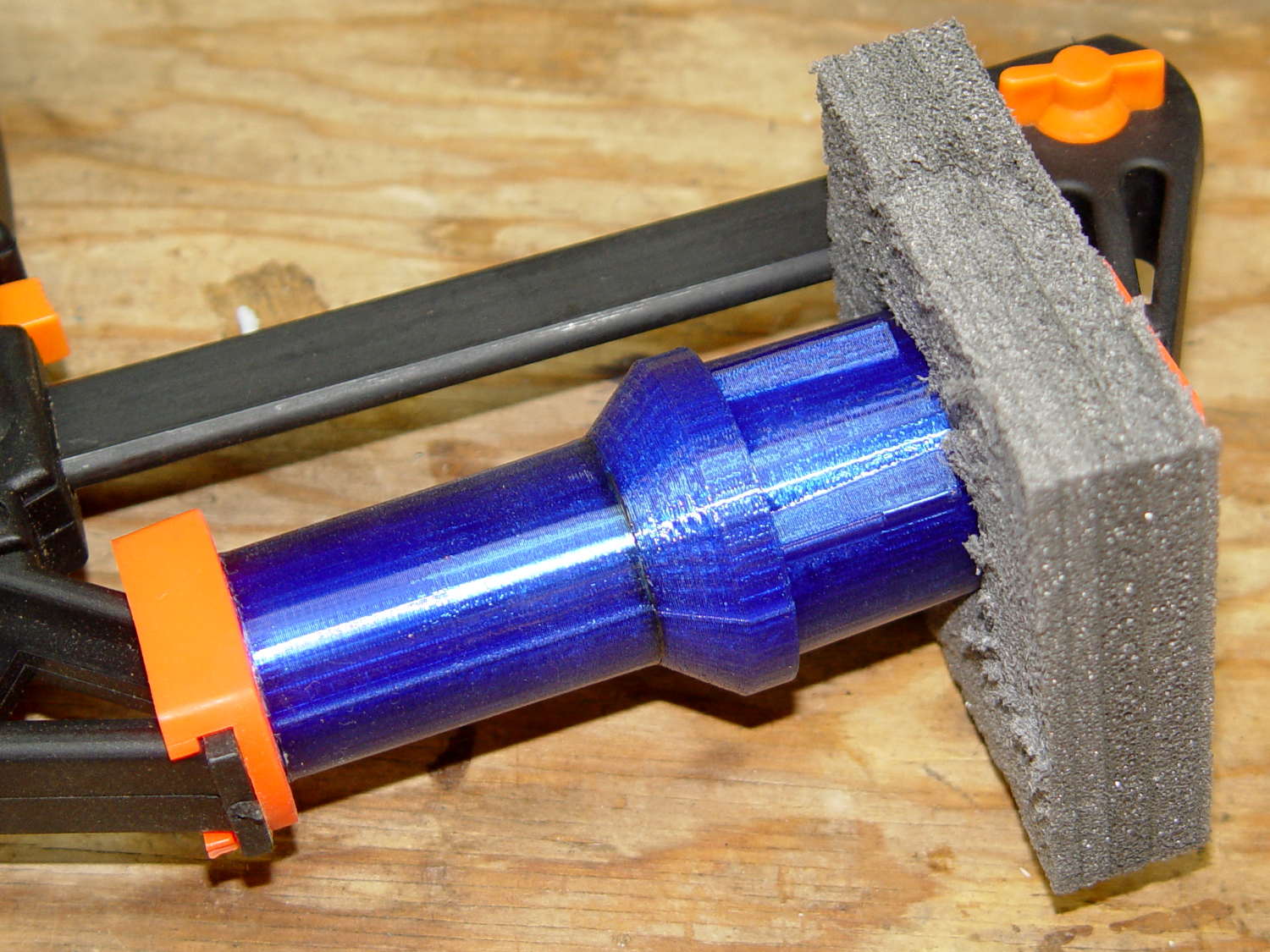
The source code now has a separate solid model for the dust brush featuring a slightly shorter snout; if when the epoxy fails, we’ll see how that changes the results. I could add ribs and suchlike along the outside, none of which seem worth the effort right now. Fairing the joint between those two straight sections would achieve the same end, with even more effort, because OpenSCAD.
The OpenSCAD source code as a GitHub Gist:
| // Kenmore vacuum cleaner nozzle adapters | |
| // Ed Nisley KE4ZNU August 2016 | |
| // Layout options | |
| Layout = "DustBrush"; // MaleFitting CoilWand FloorBrush CreviceTool ScrubbyTool LuxBrush DustBrush | |
| //- Extrusion parameters must match reality! | |
| // Print with +1 shells and 3 solid layers | |
| ThreadThick = 0.25; | |
| ThreadWidth = 0.40; | |
| HoleWindage = 0.2; | |
| function IntegerMultiple(Size,Unit) = Unit * ceil(Size / Unit); | |
| Protrusion = 0.1; // make holes end cleanly | |
| //———————- | |
| // Dimensions | |
| ID1 = 0; // for tapered tubes | |
| ID2 = 1; | |
| OD1 = 2; | |
| OD2 = 3; | |
| LENGTH = 4; | |
| OEMTube = [35.0,35.0,41.7,40.5,30.0]; // main fitting tube | |
| EndStop = [OEMTube[ID1],OEMTube[ID2],47.5,47.5,6.5]; // flange at end of main tube | |
| FittingOAL = OEMTube[LENGTH] + EndStop[LENGTH]; | |
| $fn = 12*4; | |
| //———————- | |
| // Useful routines | |
| module PolyCyl(Dia,Height,ForceSides=0) { // based on nophead's polyholes | |
| Sides = (ForceSides != 0) ? ForceSides : (ceil(Dia) + 2); | |
| FixDia = Dia / cos(180/Sides); | |
| cylinder(r=(FixDia + HoleWindage)/2,h=Height,$fn=Sides); | |
| } | |
| //——————- | |
| // Male fitting on end of Kenmore tools | |
| // This slides into the end of the handle or wand and latches firmly in place | |
| module MaleFitting() { | |
| Latch = [40,11.5,5.0]; // rectangle latch opening | |
| EntryAngle = 45; // latch entry ramp | |
| EntrySides = 16; | |
| EntryHeight = 15.0; // lower edge on *inside* of fitting | |
| KeyRadius = 1.0; | |
| translate([0,0,6.5]) | |
| difference() { | |
| union() { | |
| cylinder(d1=OEMTube[OD1],d2=OEMTube[OD2],h=OEMTube[LENGTH]); // main tube | |
| hull() // insertion guide | |
| for (i=[-(6.0/2 – KeyRadius),(6.0/2 – KeyRadius)], | |
| j=[-(28.0/2 – KeyRadius),(28.0/2 – KeyRadius)], | |
| k=[-(26.0/2 – KeyRadius),(26.0/2 – KeyRadius)]) | |
| translate([(i – (OEMTube[ID1]/2 + OEMTube[OD1]/2)/2 + 6.0/2),j,(k + 26.0/2 – 1.0)]) | |
| sphere(r=KeyRadius,$fn=8); | |
| translate([0,0,-EndStop[LENGTH]]) // wand tube butts against this | |
| cylinder(d=EndStop[OD1],h=EndStop[LENGTH] + Protrusion); | |
| } | |
| translate([0,0,-OEMTube[LENGTH]]) // main bore | |
| cylinder(d=OEMTube[ID1],h=2*OEMTube[LENGTH] + 2*Protrusion); | |
| translate([0,-11.5/2,23.0 – 5.0]) // latch opening | |
| cube(Latch); | |
| translate([OEMTube[ID1]/2 + EntryHeight/tan(90-EntryAngle),0,0]) // latch ramp | |
| translate([(Latch[1]/cos(180/EntrySides))*cos(EntryAngle)/2,0,(Latch[1]/cos(180/EntrySides))*sin(EntryAngle)/2]) | |
| rotate([0,-EntryAngle,0]) | |
| intersection() { | |
| rotate(180/EntrySides) | |
| PolyCyl(Latch[1],Latch[0],EntrySides); | |
| translate([-(2*Latch[0])/2,0,-Protrusion]) | |
| cube(2*Latch[0],center=true); | |
| } | |
| } | |
| } | |
| //——————- | |
| // Refrigerator evaporator coil wand | |
| module CoilWand() { | |
| union() { | |
| translate([0,0,50.0]) | |
| rotate([180,0,0]) | |
| difference() { | |
| cylinder(d1=EndStop[OD1],d2=42.0,h=50.0); | |
| translate([0,0,-Protrusion]) | |
| cylinder(d1=35.0,d2=35.8,h=100); | |
| } | |
| translate([0,0,50.0 – Protrusion]) | |
| MaleFitting(); | |
| } | |
| } | |
| //——————- | |
| // Samsung floor brush | |
| module FloorBrush() { | |
| union() { | |
| translate([0,0,60.0]) | |
| rotate([180,0,0]) | |
| difference() { | |
| union() { | |
| cylinder(d1=EndStop[OD1],d2=32.4,h=10.0); | |
| translate([0,0,10.0 – Protrusion]) | |
| cylinder(d1=32.4,d2=30.7,h=50.0 + Protrusion); | |
| } | |
| translate([0,0,-Protrusion]) | |
| cylinder(d1=28.0,d2=24.0,h=100); | |
| } | |
| translate([0,0,60.0 – Protrusion]) | |
| MaleFitting(); | |
| } | |
| } | |
| //——————- | |
| // Crevice tool | |
| module CreviceTool() { | |
| union() { | |
| translate([0,0,60.0]) | |
| rotate([180,0,0]) | |
| difference() { | |
| union() { | |
| cylinder(d1=EndStop[OD1],d2=32.0,h=10.0); | |
| translate([0,0,10.0 – Protrusion]) | |
| cylinder(d1=32.0,d2=30.4,h=50.0 + Protrusion); | |
| } | |
| translate([0,0,-Protrusion]) | |
| cylinder(d1=28.0,d2=24.0,h=100); | |
| } | |
| translate([0,0,60.0 – Protrusion]) | |
| MaleFitting(); | |
| } | |
| } | |
| //——————- | |
| // Mystery brush | |
| module ScrubbyTool() { | |
| union() { | |
| translate([0,0,60.0]) | |
| rotate([180,0,0]) | |
| difference() { | |
| union() { | |
| cylinder(d1=EndStop[OD1],d2=31.8,h=10.0); | |
| translate([0,0,10.0 – Protrusion]) | |
| cylinder(d1=31.8,d2=31.0,h=50.0 + Protrusion); | |
| } | |
| translate([0,0,-Protrusion]) | |
| cylinder(d1=26.0,d2=24.0,h=100); | |
| } | |
| translate([0,0,60.0 – Protrusion]) | |
| MaleFitting(); | |
| } | |
| } | |
| //——————- | |
| // eBay horsehair dusting brush | |
| module DustBrush() { | |
| union() { | |
| translate([0,0,40.0]) | |
| rotate([180,0,0]) | |
| difference() { | |
| union() { | |
| cylinder(d1=EndStop[OD1],d2=31.8,h=10.0); | |
| translate([0,0,10.0 – Protrusion]) | |
| cylinder(d1=31.6,d2=31.8,h=30.0 + Protrusion); | |
| } | |
| translate([0,0,-Protrusion]) | |
| cylinder(d1=26.0,d2=24.0,h=100); | |
| } | |
| translate([0,0,40.0 – Protrusion]) | |
| MaleFitting(); | |
| } | |
| } | |
| //——————- | |
| // Electrolux brush ball | |
| module LuxBrush() { | |
| union() { | |
| translate([0,0,30.0]) | |
| rotate([180,0,0]) | |
| difference() { | |
| union() { | |
| cylinder(d1=EndStop[OD1],d2=30.8,h=10.0); | |
| translate([0,0,10.0 – Protrusion]) | |
| cylinder(d1=30.8,d2=30.0,h=20.0 + Protrusion); | |
| } | |
| translate([0,0,-Protrusion]) | |
| cylinder(d1=25.0,d2=23.0,h=30 + 2*Protrusion); | |
| } | |
| translate([0,0,30.0 – Protrusion]) | |
| MaleFitting(); | |
| } | |
| } | |
| //———————- | |
| // Build it! | |
| if (Layout == "MaleFitting") | |
| MaleFitting(); | |
| if (Layout == "CoilWand") | |
| CoilWand(); | |
| if (Layout == "FloorBrush") | |
| FloorBrush(); | |
| if (Layout == "CreviceTool") | |
| CreviceTool(); | |
| if (Layout == "DustBrush") | |
| DustBrush(); | |
| if (Layout == "ScrubbyTool") | |
| ScrubbyTool(); | |
| if (Layout == "LuxBrush") | |
| LuxBrush(); |
The first pass at retrofitting SMD LEDs to light the needle area in Mary’s Model 158 sewing machine worked well enough:
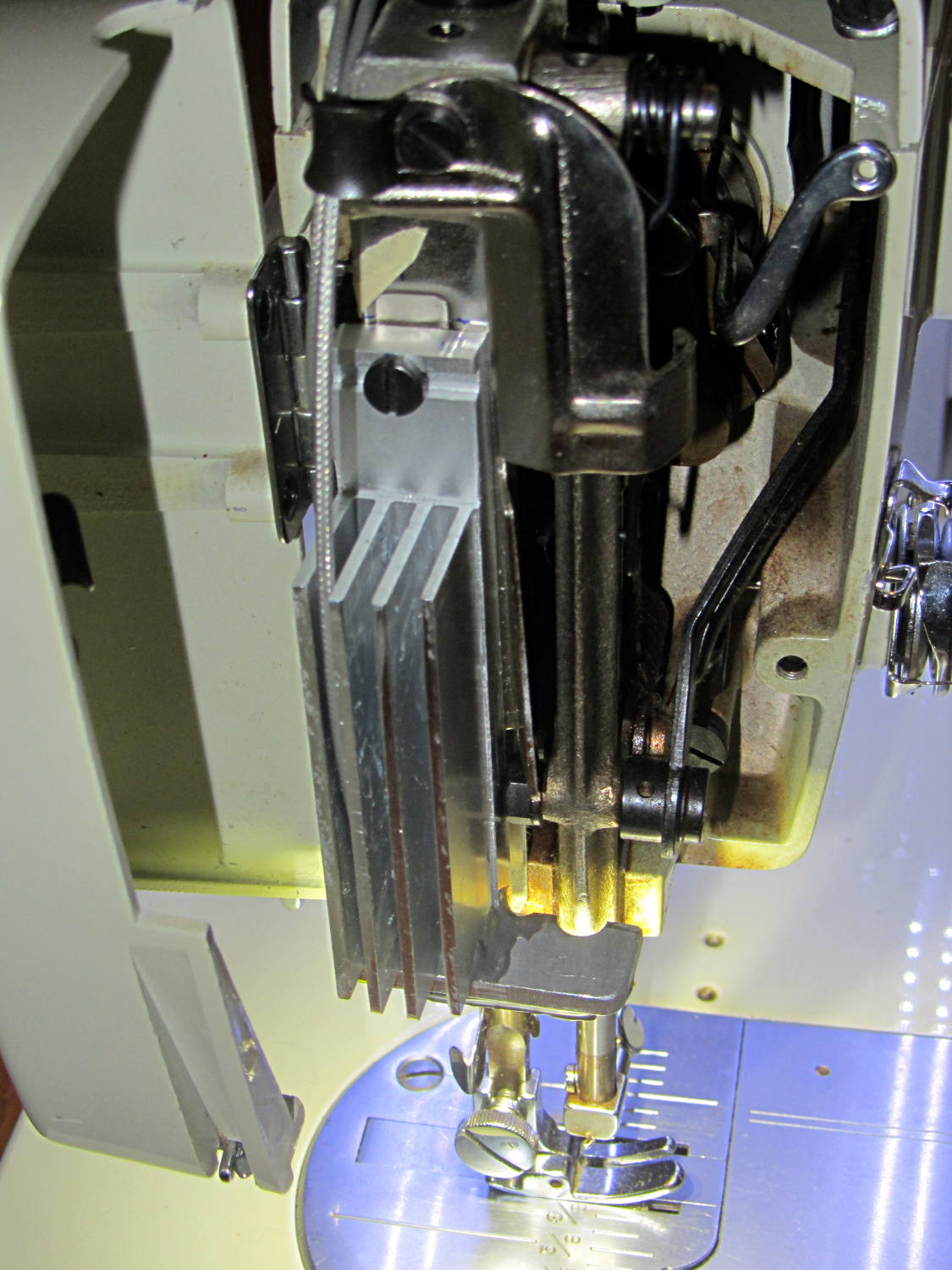
However, she wanted more light on the right side of the needle, so now she has it:
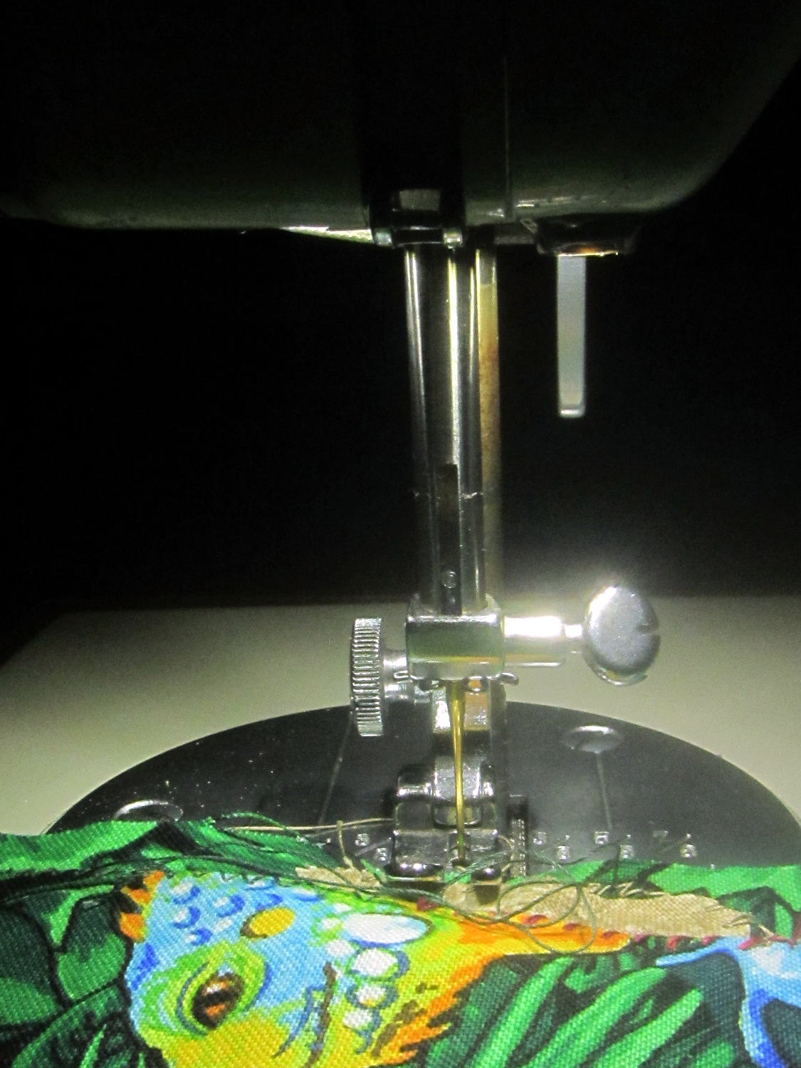
That’s without any LEDs along the front and back of the arm, hence the dark pool beyond the sewing machine’s base.
Those are the same 5050 warm white LEDs I used on the other side:
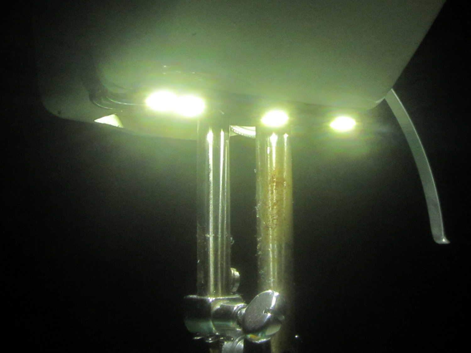
Seen without the glare:
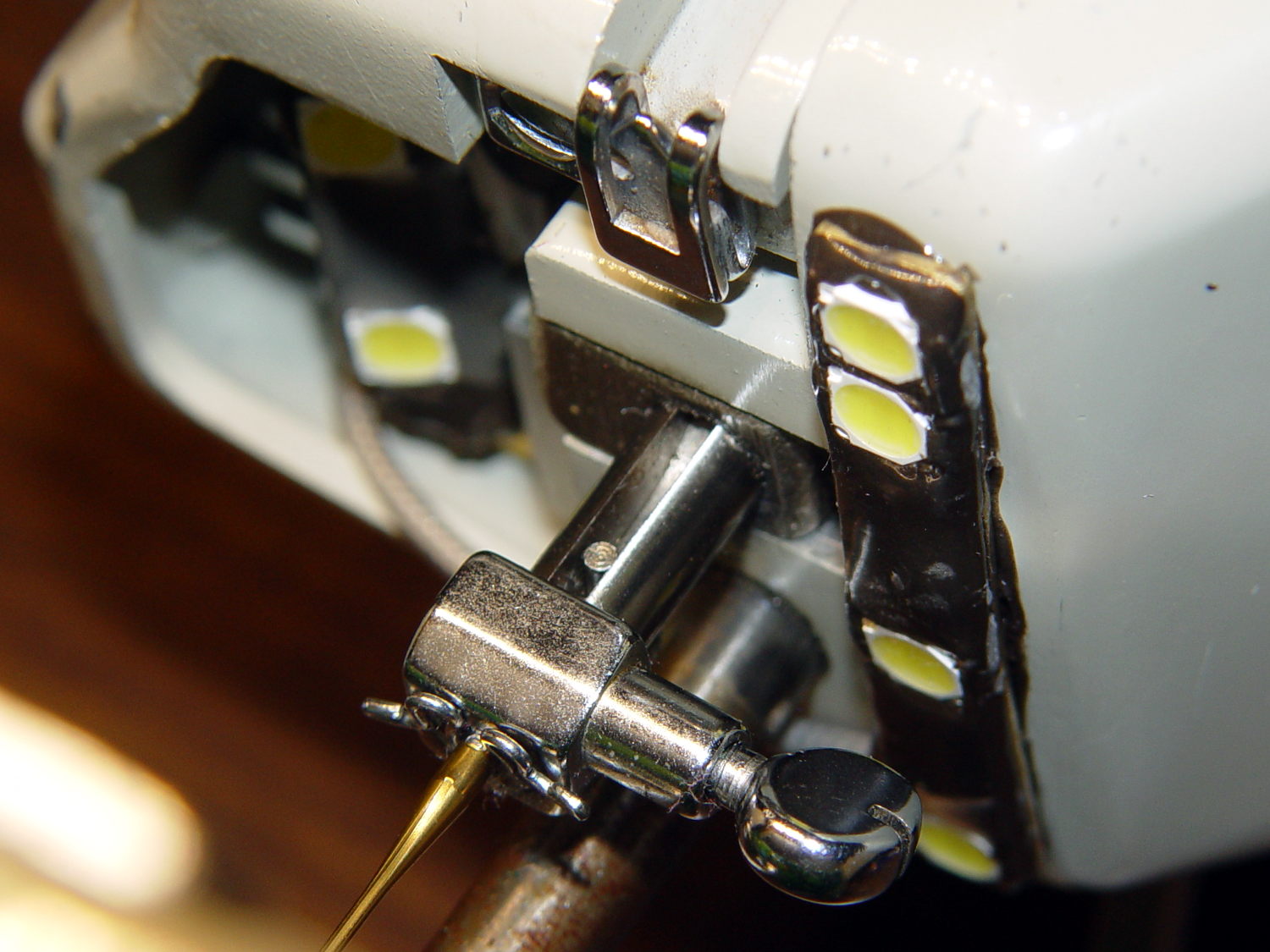
They’re mounted on a 32 mil brass strip from the shimstock stash, carefully hand-bent and twisted to match the curvature of the arm, and held in place with JB Kwik steel-filled epoxy for good heat conduction to the aluminum arm. One can argue with the epoxy oozing out from under the brass, but it’s invisible from above.
No construction photos, alas, because I made this in a white-hot frenzy one afternoon and managed to not take any pix during the entire session. Call it working in the flow, OK?
All four SMD LEDs sit in epoxy blobs that isolate them from the brass strip, with 26 AWG solid wire “bus bars” soldered to the top of their terminals and a length of that lovely PTFE-insulated miniature coax leading off into the endcap. More epoxy encloses all the wiring & connections to provide a surprisingly smooth surface that shouldn’t snag the fabric.
The power supply uses an 18 W 120 VAC to 12 VDC brick intended for small LED installations:
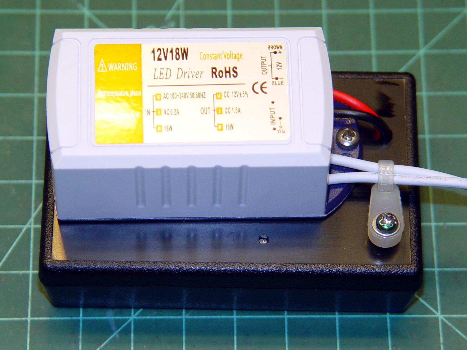
The AC comes from the same zip cord that formerly supplied the original 15 W incandescent bulb in the endcap, so the new lights behave the same way: push the power button to turn on the machine and the LEDs pop on just like they should. I put quick-disconnect terminals in the AC line to make it removable, although those need some sort of insulated plug to cover the exposed blades inside their housing.
Inside the black box, a small boost supply steps the voltage up to just under the nominal operating level of 21 VDC:
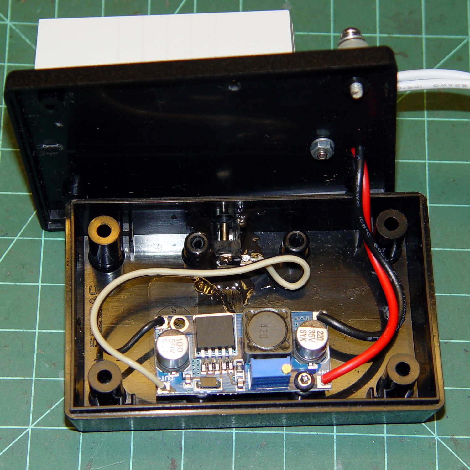
You can just see the adjusting screw hole in front of the AC brick in the overall view.
The DC output exits in the middle of the far side, through a coax jack epoxied to the base.
As before, all six LEDs run in parallel at (for now) 18.5 VDC and maybe 50 mA each, for a total of 300 mA, and seem fearsomely bright even at that. We can now tune for best light as needed.
This is a major major major improvement over the previous tangle of wires stuck on the outside of the machine, with all the wiring internal to the arm and the power supply out of sight under the sewing table.
After an hour, the arm above the four LEDs runs 13 °C above ambient and the endcap over the two LED heatsink is 6 °C over ambient. The AC supply runs at 104 °C and its plastic case offers no provision for heatsinking. All in all, things are warm and not hazardous.
I haven’t retrofit this machine with LED strips along the front & back of the arm, as those may not be needed with the intense needle lighting; the NisLite desk lamp may suffice for area illumination.
This turned out surprisingly well:

In the harsh light of the Electronics Workbench, you can see there’s less than meets the eye: a single knockoff Neopixel taped to the back side of the bulb just below the equator and a knockoff Arduino Pro Mini taped to the Mogul lamp socket:

The electrical box serves as a base and the cord doesn’t do anything in this incarnation.
The 5050 SMD LED package (inside an ugly 3D printed plate cap) looks enough like a point source to shadow the filament & support structure against the frosted bulb. The blurry upper part of the filament is closer to the LED, which isn’t really a point source and must fight its way through the frosting.
The Pro Mini runs the same firmware as the Bowl o’ Fire floodlamp, of course, dialed back for slow fades.
It lights up the room something wonderful …
