The Smell of Molten Projects in the Morning

Ed Nisley's Blog: Shop notes, electronics, firmware, machinery, 3D printing, laser cuttery, and curiosities. Contents: 100% human thinking, 0% AI slop.

Author: Ed

  • Smithsonian’s Apollo 11 Command Module

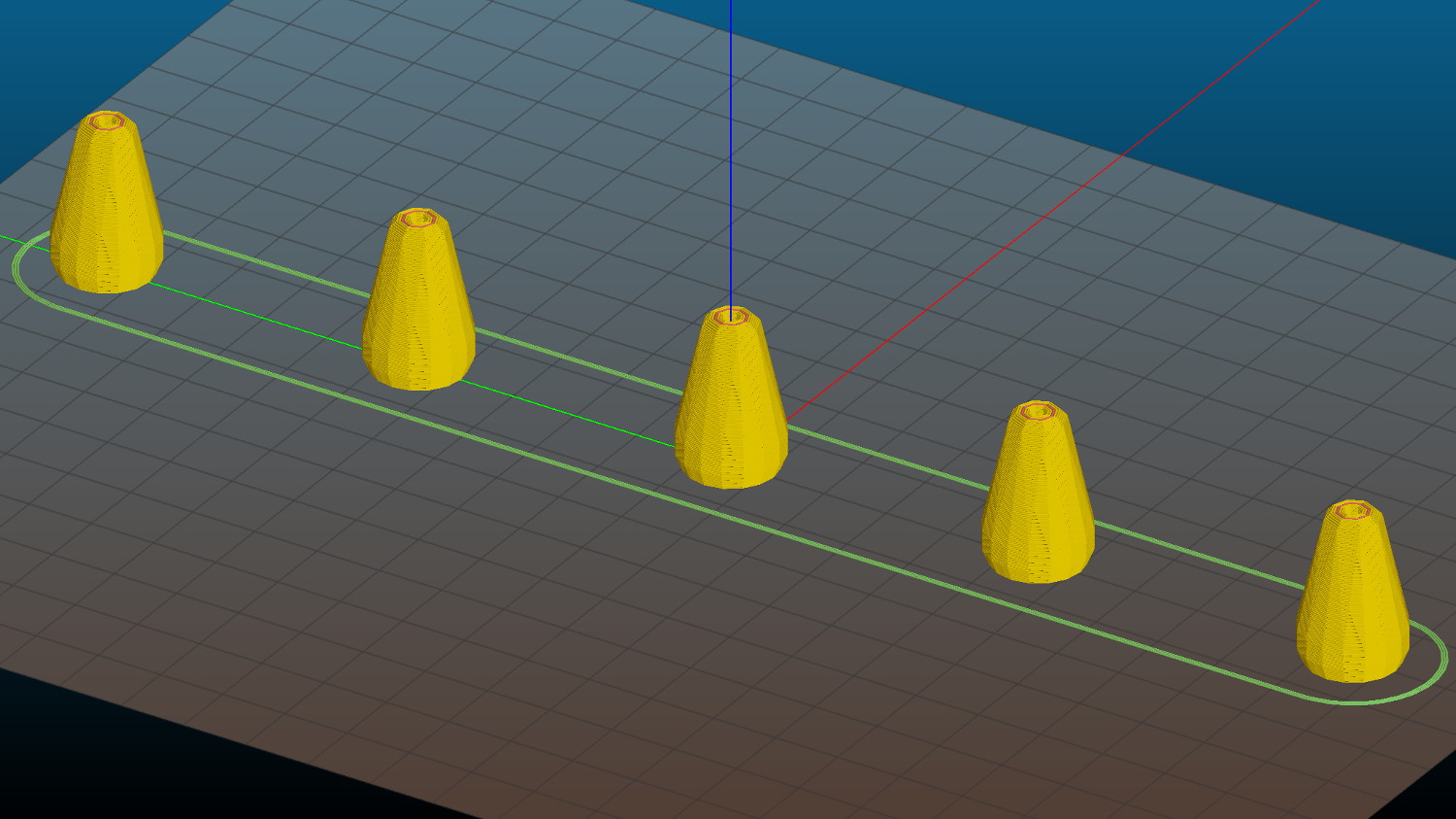
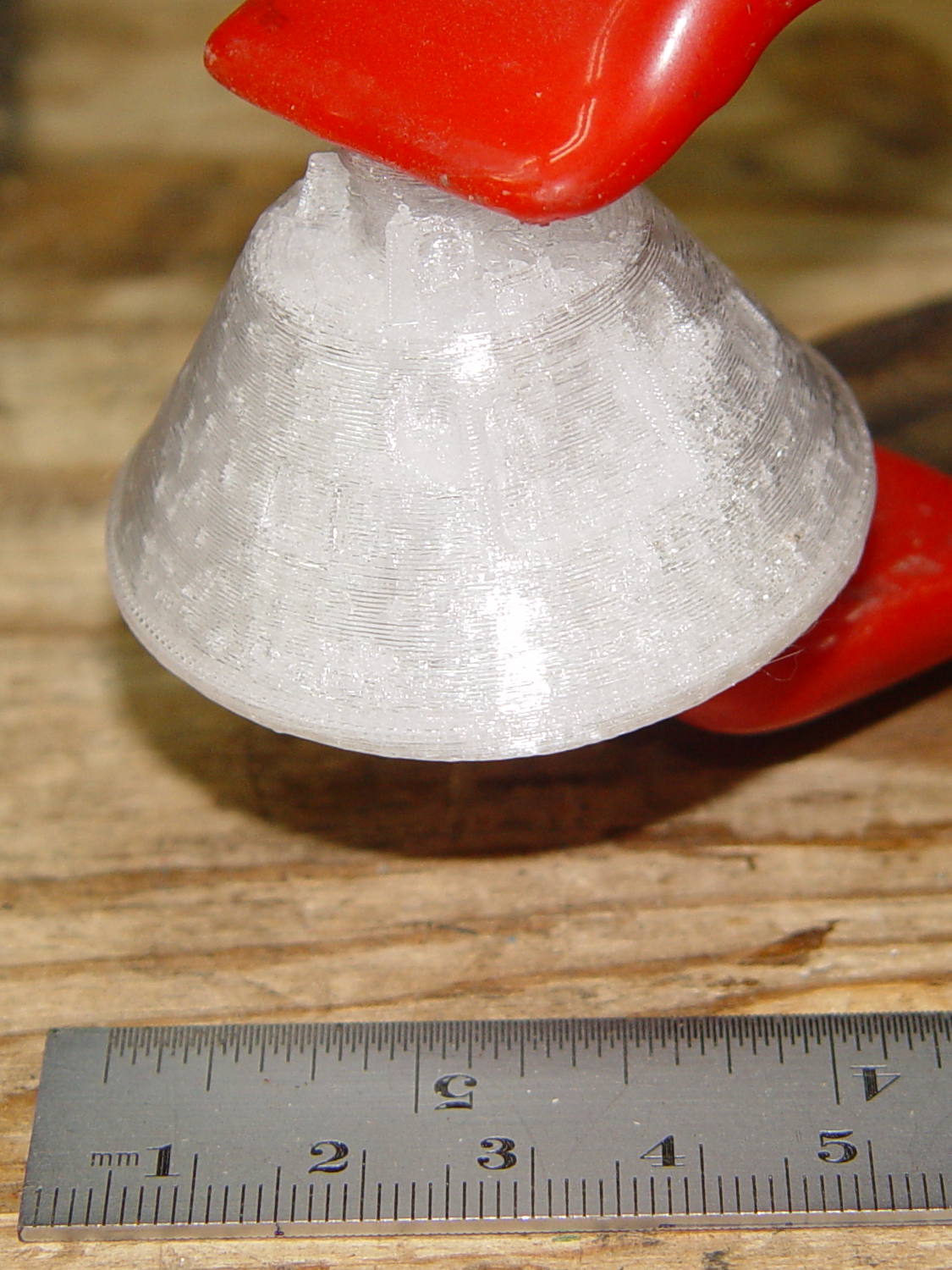
    An old friend asked for a copy of the Smithsonian’s Apollo 11 Command Module. I started with a tiny 1:80 version to check feasibility:

    Apollo 11 CM - 1-80 scale
    Apollo 11 CM – 1-80 scale

    It’s obviously not printable in one piece without a ton of support, so I chopped off the heatsink and printed the parts separately in the obvious orientation:

    Apollo 11 CM - 1-80 scale - split - Slic3r preview
    Apollo 11 CM – 1-80 scale – split – Slic3r preview

    And glued them back together:

    Apollo 11 CM - clamping
    Apollo 11 CM – clamping

    That worked well enough, even without locating pins, to give me confidence that it’d come out all right.

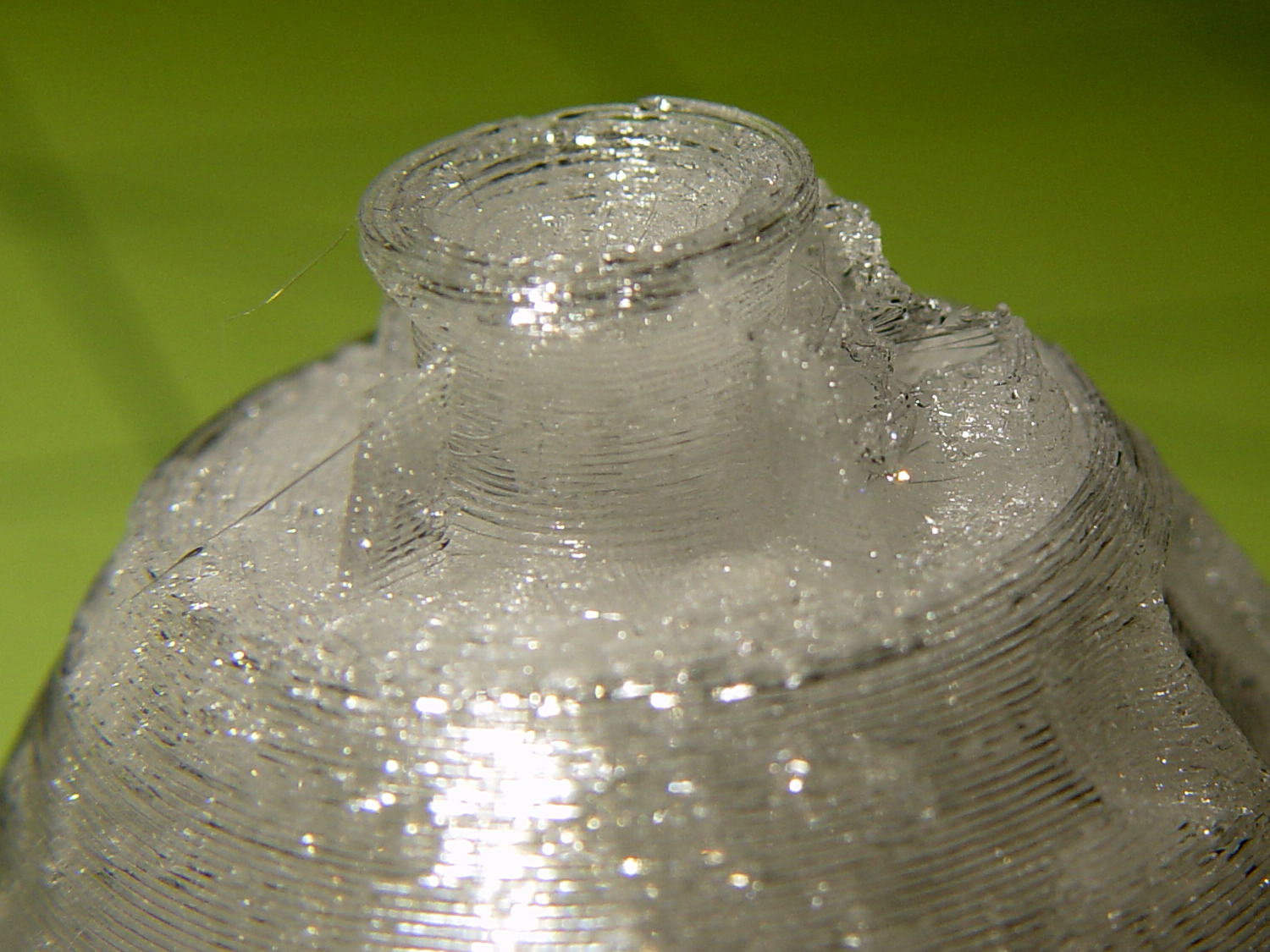
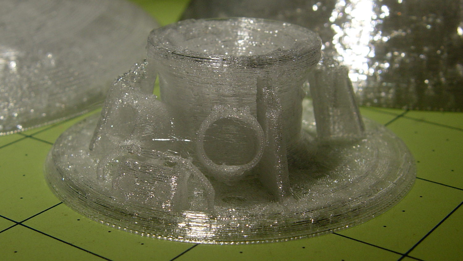
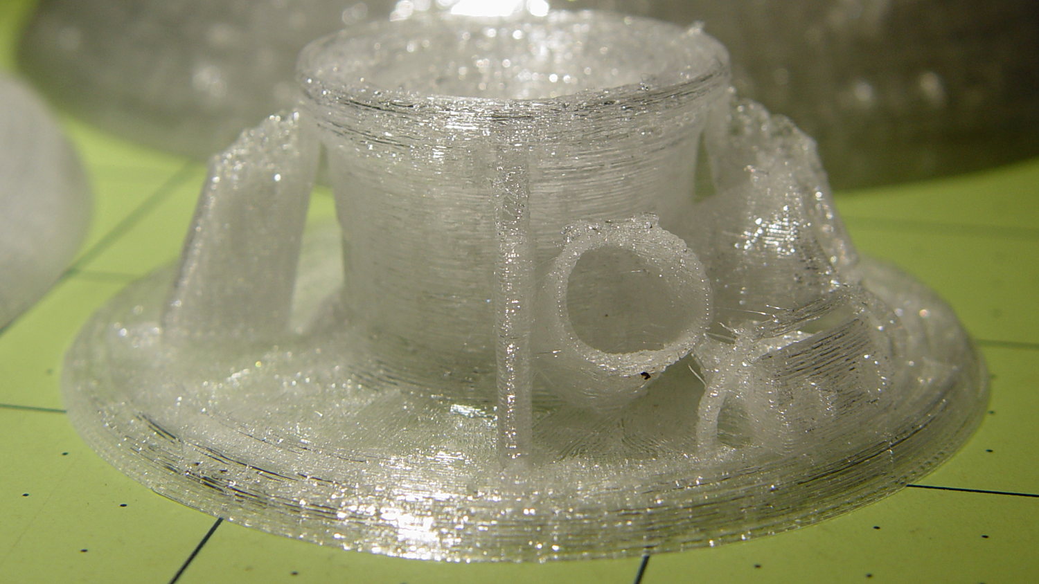
    There’s plenty of gimcrackery surrounding the upper airlock:

    Apollo 11 CM - 1-40 scale - top - Slic3r preview
    Apollo 11 CM – 1-40 scale – top – Slic3r preview

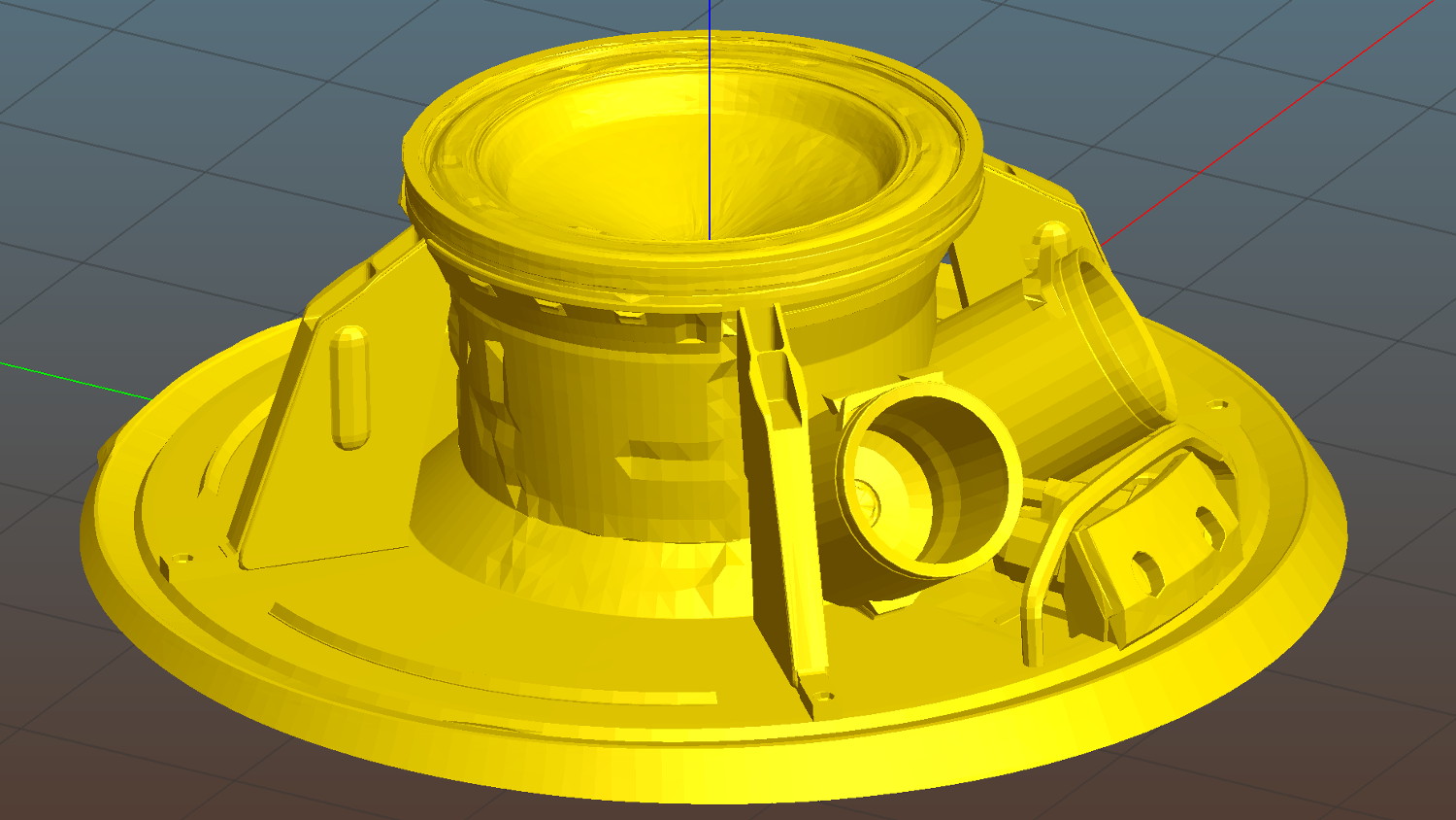
    Most of which simply vanished at 1:80 scale:

    Apollo 11 CM - 1-80 scale - top detail
    Apollo 11 CM – 1-80 scale – top detail

    I made another cut just below the top of the capsule and ran off a 1:40 scale version that came out somewhat better, but it was still ugly:

    Apollo 11 CM - 1-40 scale - mortar detail
    Apollo 11 CM – 1-40 scale – mortar detail

    Much to my astonishment, the grab rail over the side hatch, between the two parachute motars, came out well every time.

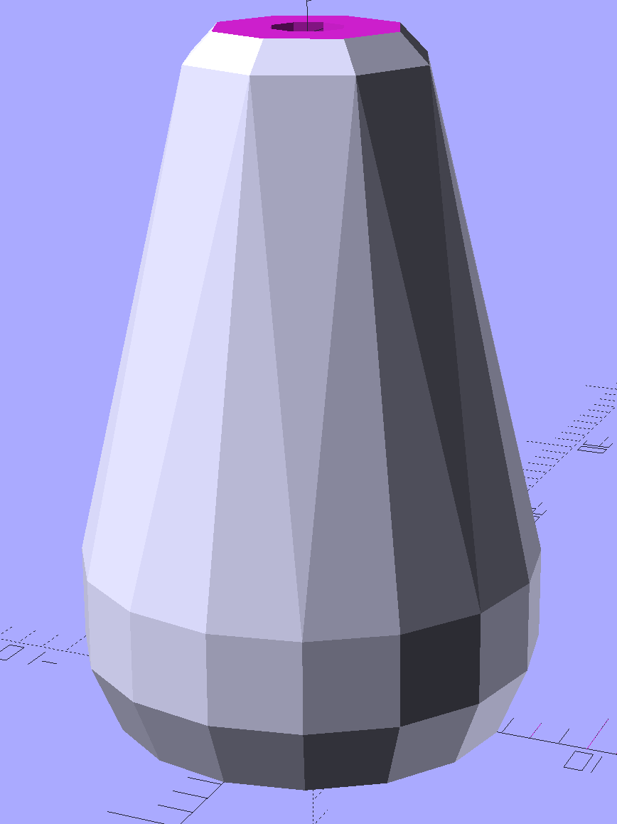
    The giant 1:20 scale version would require something over 24 hours of printing, so I went with 1:30 in three pieces:

    Apollo 11 CM - 1-30 scale - sections
    Apollo 11 CM – 1-30 scale – sections

    The top had pretty good detail:
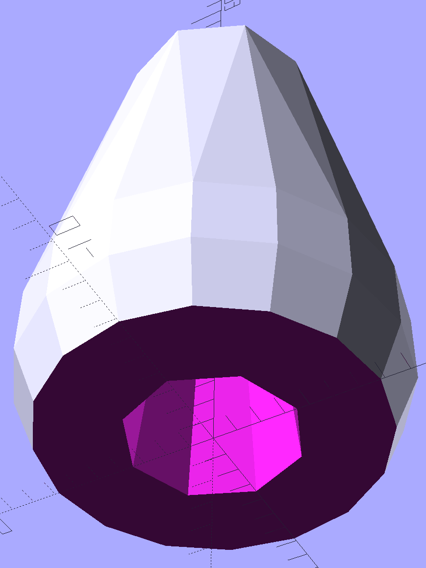
    Apollo 11 CM - 1-30 scale - top section - 1
    Apollo 11 CM – 1-30 scale – top section – 1

    Another view:

    Apollo 11 CM - 1-30 scale - top section - 2
    Apollo 11 CM – 1-30 scale – top section – 2

    Gluing the parts together made it ready for cleanup / finishing / painting:

    Apollo 11 CM - 1-30 scale - assembled
    Apollo 11 CM – 1-30 scale – assembled

    Which he’s better at than I ever will be…

    Natural PETG probably isn’t the right plastic for that kind of model, but it’s what I had on hand.

    Enjoy!

  • JYE Tech DSO138 Oscilloscope

    DSO138 oscilloscope, along with the FG085 function generator, could form the basis of an entry-level electronics bench:

    JYE Tech - FG085 Fn Gen - DS138 Oscilloscope
    JYE Tech – FG085 Fn Gen – DS138 Oscilloscope

    Neither of the kits require advanced assembly skills, but neophytes would definitely benefit from somebody who could guide them through the rough spots. In fact, JYE Tech comped me the acrylic scope case in return for the defects on the function generator PCB: thanks!

    Just to rub it in, I suppose, one of the 2 mm nuts required to assemble the case missed the threading operation:

    Unthreaded 2 mm nut
    Unthreaded 2 mm nut

    Took me a while to figure out why I couldn’t make the screw work. No big deal if you’ve got stuff, but it’d be a showstopper for a newbie.

    Anyhow, the kit went together smoothly and powered right up:

    JYE Tech DSO138 oscilloscope - 1 kHz sine
    JYE Tech DSO138 oscilloscope – 1 kHz sine

    The trace arithmetic functions work well enough:

    DSO138 oscilloscope screen - trace data
    DSO138 oscilloscope screen – trace data

    The triggering seems finicky and setting the level sometimes moves the trace baseline, although that may be due to my fat-fingering the controls.

    The front end is noisy, the bandwidth limited, the screen is small, and you can’t capture / export traces to your PC / cloud / whatever.

    It’s an OK starter scope and you’ll shortly realize why you need a dual-trace scope…

  • Cast Iron Pan Electrolysis Stripping

    Our cast iron pans need seasoning, so I decided to start with full-metal-jacket electrolysis stripping, rather than soaking them in oven cleaner / smogging the kitchen with the self-cleaning oven / actually doing any work. The electrolysis setup involves the big battery charger and a bucket of sodium carbonate solution:

    Cast iron pan electrolysis - setup
    Cast iron pan electrolysis – setup

    Although the charger has a 40 A capacity, the small pan bubbles along merrily at a self-limited 7 A:

    Cast iron pan electrolysis - bucket
    Cast iron pan electrolysis – bucket

    The anode is a big sheet of steel that was once an EMI shield in a big PC case. The side facing the pan corroded very quickly, but the outside remains in good shape and I think it’ll suffice for the medium and large pans.

    After two hours, only the crustiest bits of the crust remained:

    Cast iron pan electrolysis - 2 hours
    Cast iron pan electrolysis – 2 hours

    Those flakes fell right off after a few pokes from my demolition scraper; definite anticlimax, that.

    Another hour in the tank cleaned the handle and removed a few other spots; it now sports a layer of flash rust that’ll require another pass after I strip the other two pans…

  • Wasp Flyby

    I didn’t notice this at the time:

    This slideshow requires JavaScript.

    The camera runs at 60 frame/s, so the entire show spans a bit more than half a second: zzzzzip!

    I think it’s a member of the Yellow Jacket wasp family, noted for their in-your-face attitude and repeat-fire stinger. They’re highly capable flying machines, that’s for sure…

    We were pulling out of the local “health food” store with fresh-ground nut butters in the packs, nearing the end of a 17 mile loop on a fine Sunday morning.


  • Miniblind Cord Caps

    After smashing one of the cord pulls between the sash and the frame:

    Miniblind cord caps - installed
    Miniblind cord caps – installed

    The glittery PETG looks surprisingly good in the sunlight that will eventually change it into dullness. The black flecks come from optical effects in the plastic, not the usual burned PETG snot.

    The solid model is basically a hull around two “spheres”, truncated on top & bottom:

    Miniblind cord cap - solid model
    Miniblind cord cap – solid model

    The interior has a taper to accommodate the knot, but they’re chunky little gadgets:

    Miniblind cord cap - solid model - bottom
    Miniblind cord cap – solid model – bottom

    I thought the facets came out nicely, even if they’re mostly invisible in the picture.

    Each pull should build separately to improve the surface finish, so I arranged five copies in sequence from front to back:

    Miniblind cord cap - 5 sequential - Slic3r preview
    Miniblind cord cap – 5 sequential – Slic3r preview

    If you’re using an M2, the fans hanging off the front of the filament drive housing might come a bit too close for comfort, so rotate ’em upward and out of the way.

    If you remove the interior features and flip ’em upside down, they’d work well in Spiral Vase mode. You’d have to manually drill the top hole, though, because a hole through the model produces two shells.

    The OpenSCAD source code as a GitHub Gist:

    // Cap for miniblind cord
    // Ed Nisley KE4ZNU – August 2016
    //- Extrusion parameters – must match reality!
    ThreadThick = 0.25;
    ThreadWidth = 0.40;
    Protrusion = 0.1;
    HoleWindage = 0.2;
    //——
    // Dimensions
    OD1 = 0;
    OD2 = 1;
    LENGTH = 2;
    Cap = [9.0,16.0,25.0];
    Cord = [2.5,7.0,Cap[LENGTH] – 5];
    NumSides = 8;
    //———————-
    //- Build it
    difference() {
    hull() { // overall shape
    translate([0,0,Cap[LENGTH] – Cap[OD1]/2])
    sphere(d=Cap[OD1],$fn=NumSides);
    translate([0,0,0.5*Cap[OD2]/2])
    sphere(d=Cap[OD2],$fn=2*NumSides); // round the bottom just a bit
    }
    translate([0,0,-Cap[LENGTH]/2]) // trim bottom
    cube([2*Cap[OD2],2*Cap[OD2],Cap[LENGTH]],center=true);
    translate([0,0,Cap[LENGTH] + 0.8*Cap[OD1]]) // trim top (arbitrarily)
    cube([2*Cap[OD1],2*Cap[OD1],2*Cap[OD1]],center=true);
    translate([0,0,-Protrusion])
    cylinder(d=Cord[OD1],h=(Cap[LENGTH] + 2*Protrusion),$fn=NumSides);
    translate([0,0,-Protrusion])
    cylinder(d1=Cord[OD2],d2=Cord[OD1],h=(Cord[LENGTH] + Protrusion),$fn=NumSides);
    }
  • Counterfeit FTDI USB-Serial Adapter Roundup

    As part of the vacuum tube lighting project, I picked up a bunch of USB-Serial adapters, with the intent of simply building them into the lamp base along with a knockoff Arduino Pro Mini, then plugging in a cheap USB wall wart for power. An Arduino Nano might make more sense, but this lets me use the Pro Minis for other projects where power comes from elsewhere.

    Anyhow, I deliberately paid a few bucks extra for “genuine” FTDI chips, knowing full well what was about to happen:

    Assorted FT232 Converters
    Assorted FT232 Converters

    The two boards on the bottom have been in my collection forever and seem to be genuine FTDI; the one on the left came from Sparkfun:

    FT232RL - genuine
    FT232RL – genuine

    The top six have counterfeit chips, although you’d be hard-pressed to tell from the laser etching:

    FT232RL - fake
    FT232RL – fake

    In addition to the boards, I picked up the blue square-ish cable adapters for the HP 7475A plotter project and, again, paid extra for “genuine” FTDI chips. The other adapters, based on Prolific PL2303 chips, I’ve had basically forever:

    Assorted FT232 Converters - Cabled
    Assorted FT232 Converters – Cabled

    Those two have chips with different serial numbers: genuine FTDI chips get different serial numbers programmed during production. The counterfeits, well, they’re all pretty much the same.

    Display the serial numbers thusly:

    lsusb
    Bus 002 Device 024: ID 0403:6001 Future Technology Devices International, Ltd FT232 Serial (UART) IC
    ... snippage ...
    udevadm info --query=all --attribute-walk  --name=/dev/bus/usb/002/024 | grep ser
        ATTR{serial}=="A6005qSB"
    

    All the counterfeit FTDI chips report the same serial number: A50285BI. The PL2303 chips don’t report serial numbers.

    For my simple needs, they all work fine, but apparently fancier new microcontrollers expect more from their adapters and the counterfeits just can’t live up to their promises.

    For a while, FTDI released Windows drivers that bricked counterfeit chips; the Linux drivers were unaffected.

  • Monthly Science: Sony NP-BX1 Battery Status

    Having had the weaker of the two surviving STK batteries die 36 minutes into a ride, I tested them all:

    Sony NP-BX1 - 1 A test - 2016-08-17
    Sony NP-BX1 – 1 A test – 2016-08-17

    The X axis shows W·h, rather than the usual A·h, because that seems more useful in a world of constant-power supplies.

    The test current is now 1 A, rather than the previous 500 mA, to more closely match the camera’s actual load. The CBA tester doesn’t have a constant-power mode; I think that doesn’t make much practical difference.

    The orange curve (STK D) is the failed battery, ending after 1.4 W·h. At an average 3.2-ish V, that’s 26 minutes, which is close enough to the actual run time, given the different current.

    The red curve (STK C) is the sole STK battery of the original four from last November that actually worked.

    The upper two curves come from the mostly unused Wasabi batteries (F and G), also from November. They have lost a bit of their capacity, but show the highest voltage out toward the end, so that’s good.

    The black curve is the lightly used Sony OEM battery that came with the camera. Although it has about the same ultimate capacity as the other three “good” batteries, the voltage depression suggests it’ll trip out early.

    The others are pretty much debris by now. I suppose they might be good for LED blinkies or some other low-voltage and low-current application, but …

    So I’ll start using all four of the better batteries and see how the run times work out in actual use.