Ed Nisley's Blog: Shop notes, electronics, firmware, machinery, 3D printing, laser cuttery, and curiosities. Contents: 100% human thinking, 0% AI slop.
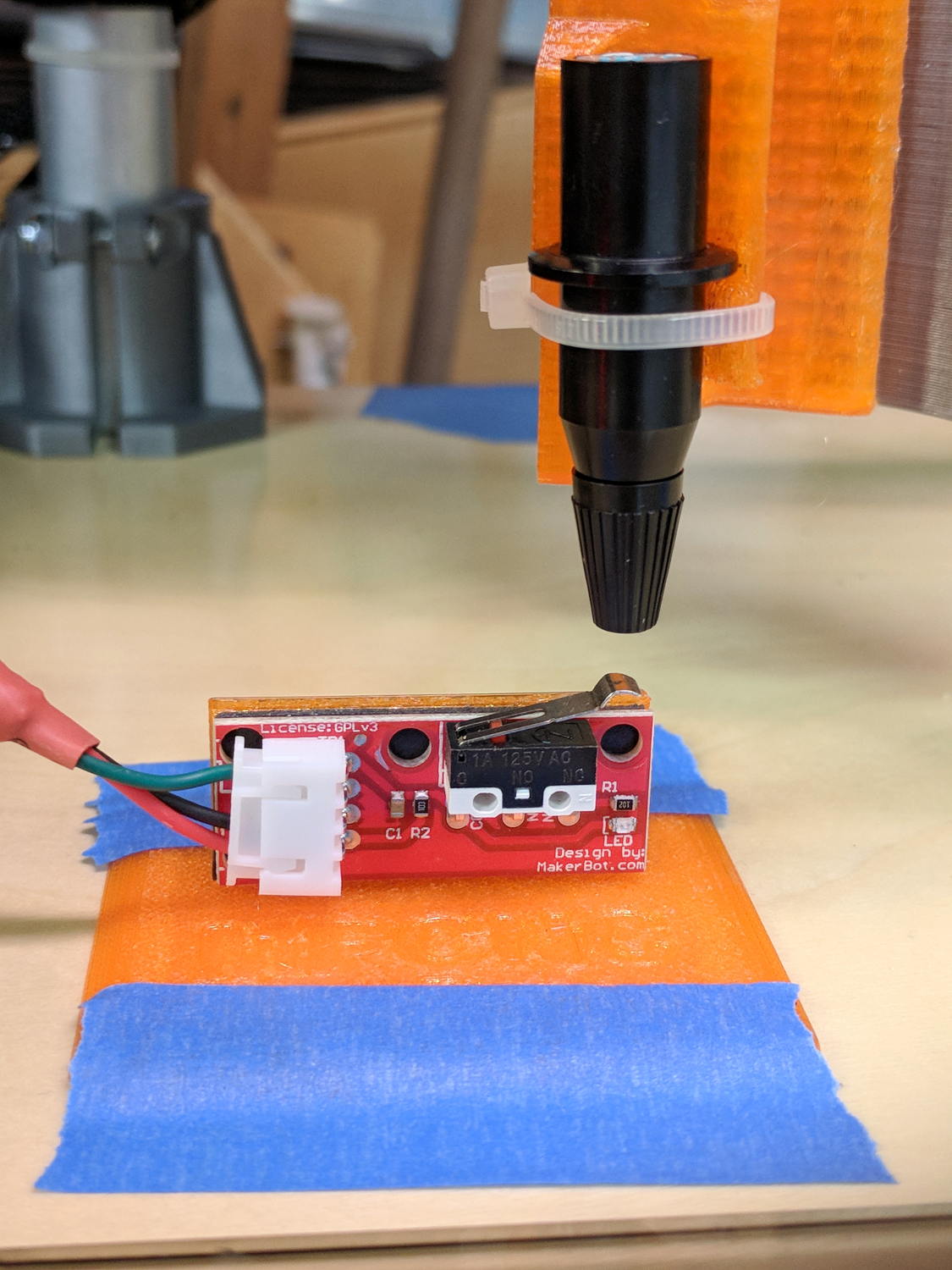
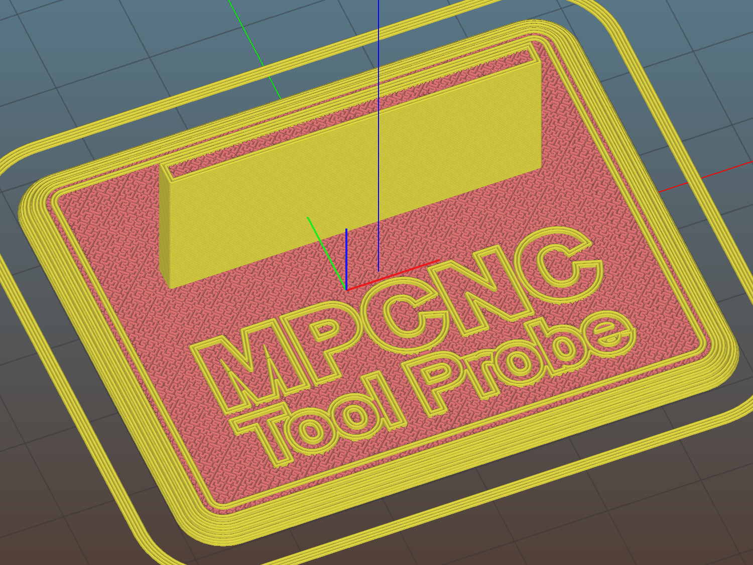
The flange offset puts the switch actuator on the midline of the base, not that that matters, and the base features rounded corners and a suitable legend, because I can.
I clipped the PCB’s through-hold leads nearly flush and stuck it to the flange with 3M permanent foam tape, which seems to work much better than screws & inserts for simple things that need never come apart.
The Protoneer CNC Shield includes a Probe input on the GRBL-compliant A5, although it took me a while to find the legend on the SCL pin in the I2C header. I moved the endstop power jumper to another header, then conjured a quick-and-dirty connector:
Protoneer CNC Shield – Tool Probe Wiring
When I embed the endstop switch PCB in epoxy, I’ll add a drop to the connector while engaging in Magical Thinking. The whole Arduino + CNC Shield must go into an enclosure after I finish measuring the motor currents.
To forestall discussions about switch repeatability and accuracy, suffice it to say the MPCNC doesn’t claim to be much more than a woodworking router, so those switches seem Good Enough.
This file contains hidden or bidirectional Unicode text that may be interpreted or compiled differently than what appears below. To review, open the file in an editor that reveals hidden Unicode characters.
Learn more about bidirectional Unicode characters
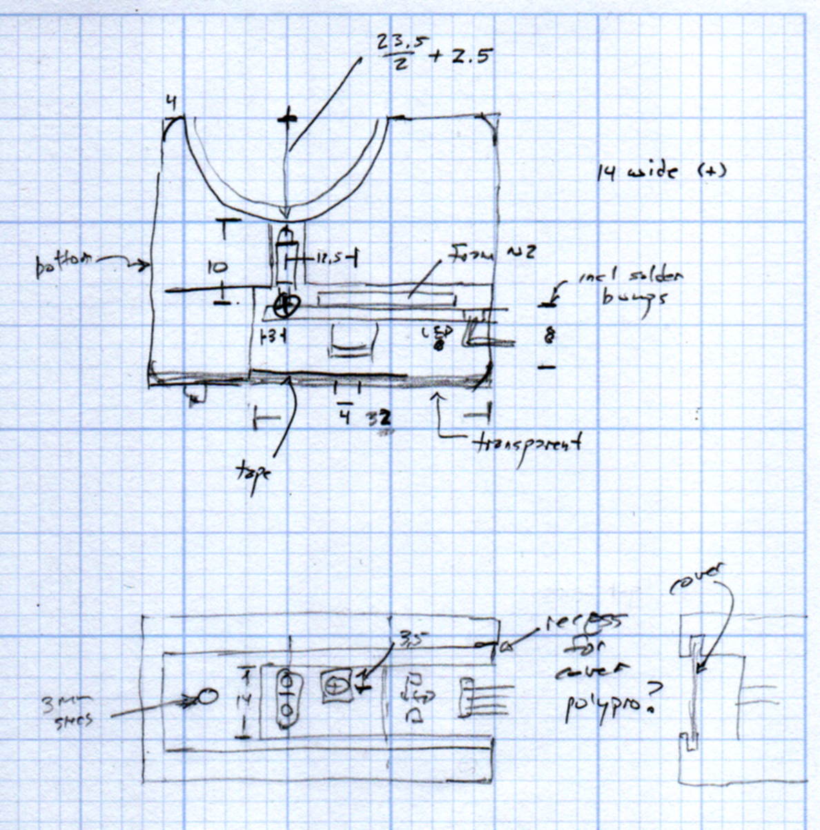
The original doodles show a severely over-complexicated solution desperately searching for an actual problem:
MPCNC Tool Length Probe – doodles
Putting a large flat pan at the end of a relatively long lever arm, with the pivot arranged to put the pan level at the switch actuation point, made sense at the time. Give the relatively small tools I expect to use, directly ramming them into the switch lever should work just as well.
Putting all that complexity in harm’s way seemed like a Bad Idea when I sat down and looked at it in cold blood.
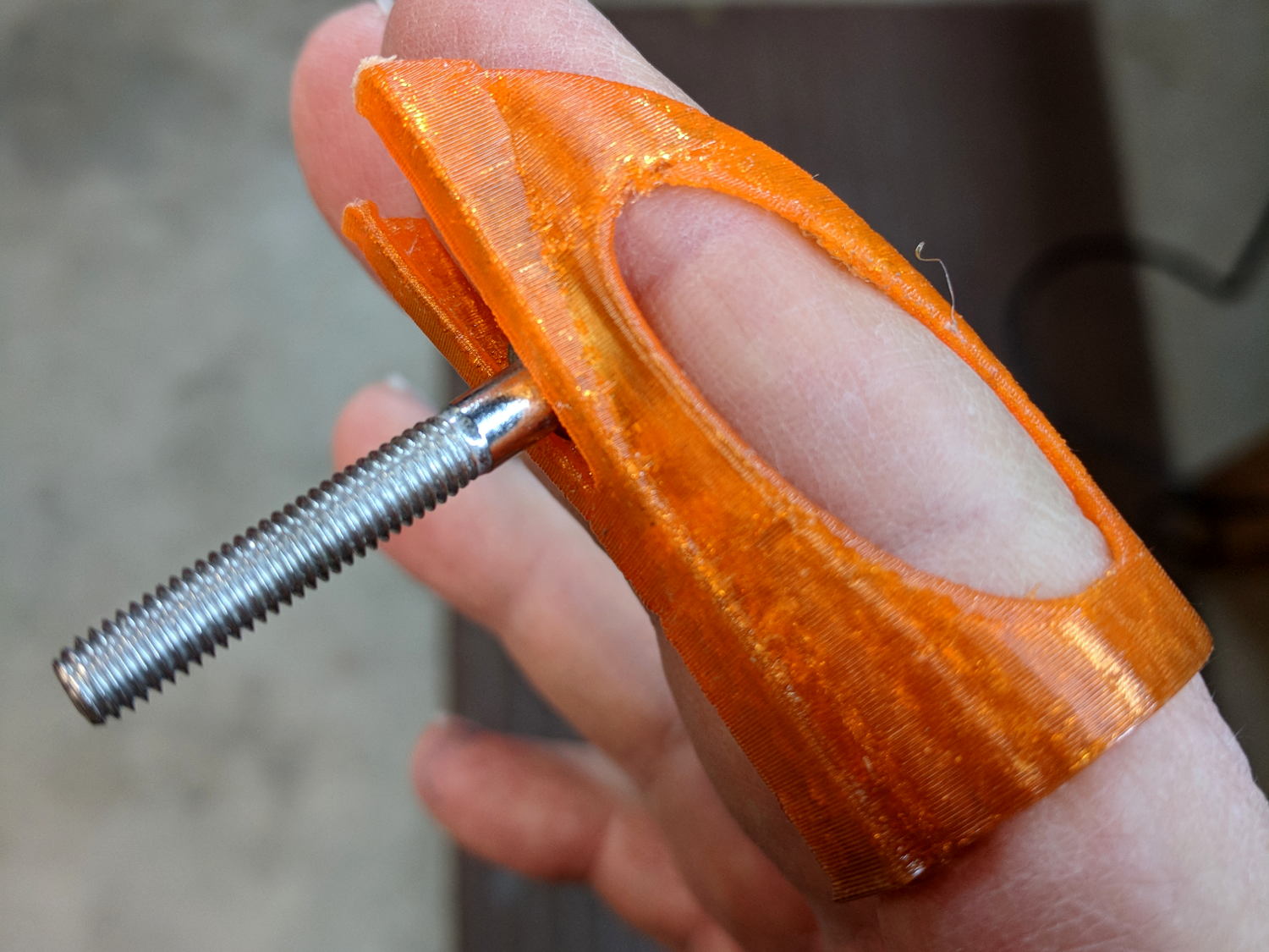
A friend recommended a Finger Wrench and it looks useful, indeed:
Finger Wrench
That’s a 10-32 socket head cap screw, on the large end of the screws I normally use.
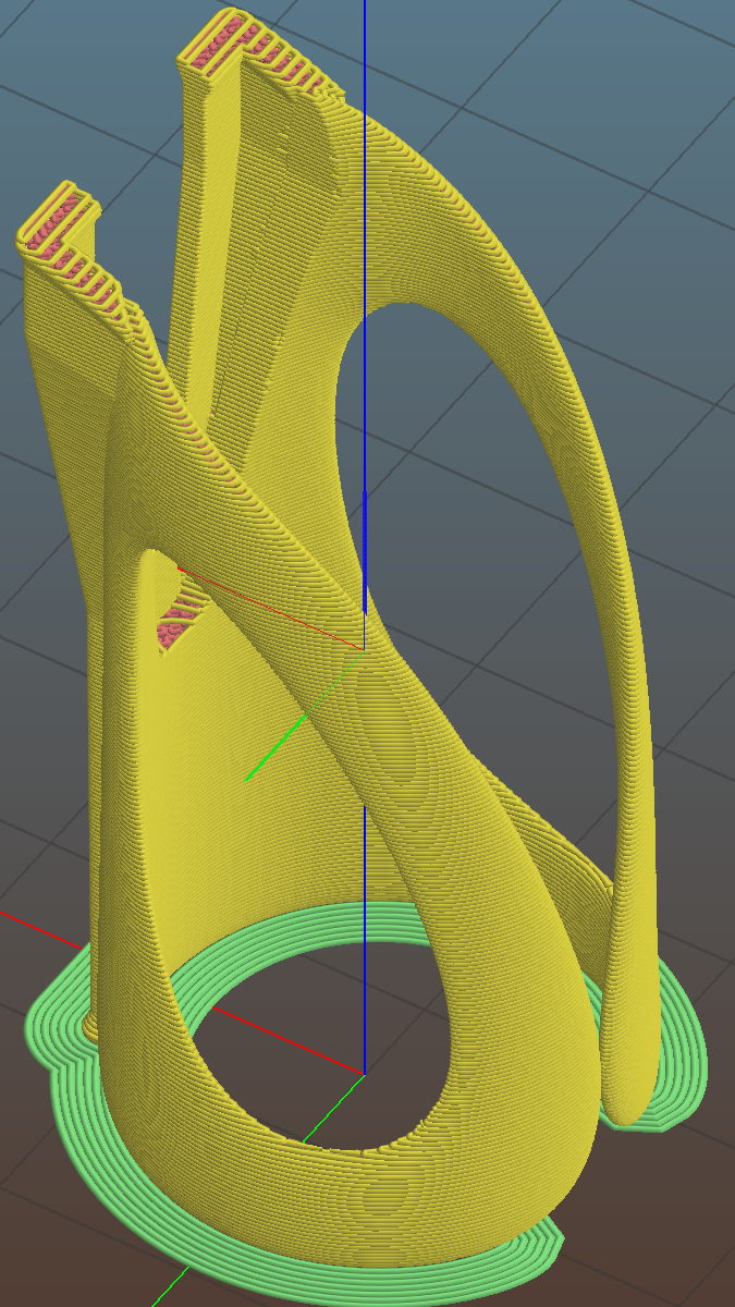
The orange PETG required a bit of smoothing around the overhangs, but should work well enough. The dark tinge near the bottom comes from the black filament I used for the MPCNC’s Z Axis sensor and won’t affect its operation in the least.
Done with one perimeter thread and a 3 mm brim to glue down the bottom:
Following all the steps recommended by Cycliq Tech Support didn’t improve the situation. It’s just under two years old and thus outside the warranty, so they advised me to buy their new, not-quite-released-yet Fly6, now with Bluetooth / ANT+ / phone app / shiny, but still with a non-replaceable battery.
Seeing as how the Fly6 works as well as it ever did, apart from the minor issue of shutting down both dependably and intermittently, the problem is almost certainly a bad battery. Cycliq does not offer a repair service, nor a battery replacement service; being based in Australia probably contributes to not wanting to get into those businesses. You’re supposed to responsibly recycle the Whole Damn Thing when the battery goes bad. Which, inevitably, it does.
Protip: anything with a non-replaceable battery is a toy, not a tool.
The most recent ride gave some evidence supporting a bad battery. The first shutdown happened after about half an hour and it gave off three battery status beeps (four = full charge, as at the start of the ride) when I restarted it a few minutes later. It shut down again a few minutes later while we were stopped at a traffic signal and gave off one lonely charge beep when I reached back to restart it, indicating a very low battery voltage. The battery voltage (and the number of startup beeps) increased with longer delays between shutdown and restart, but after the first shutdown it’s never very enthusiastic.
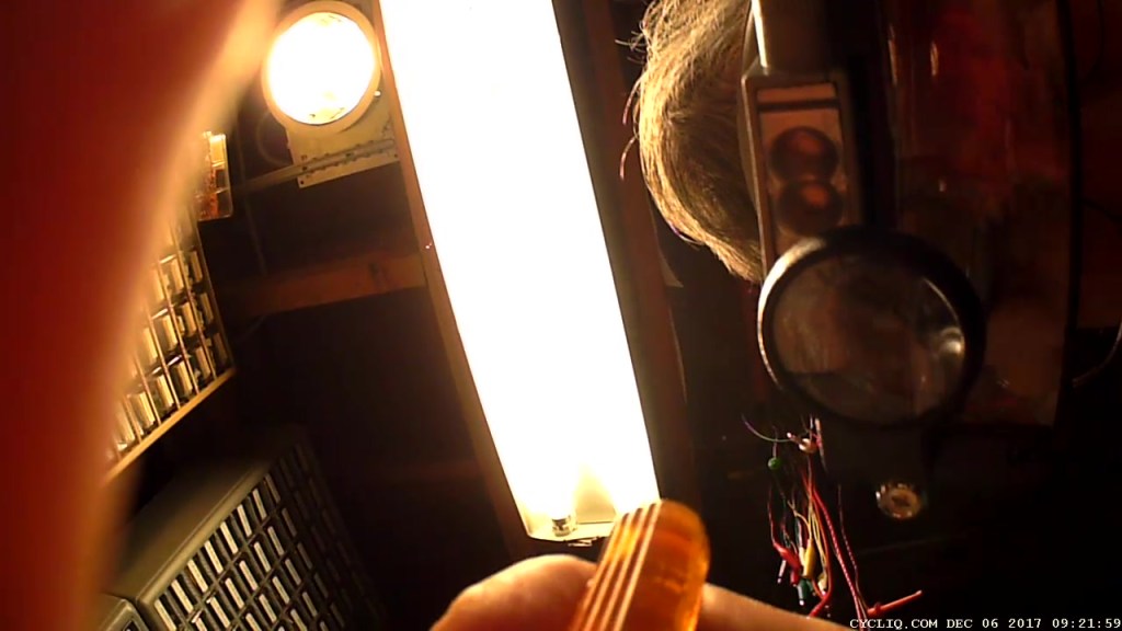
Having nothing to lose, let’s see what’s inside:
Cycliq Fly6 Teardown from inside
Don’t do as I did: you should extract the MicroSD card before you dismantle the camera.
Remove the rubber plugs sealing the four case screws:
Fly6 – Exterior screw plugs out
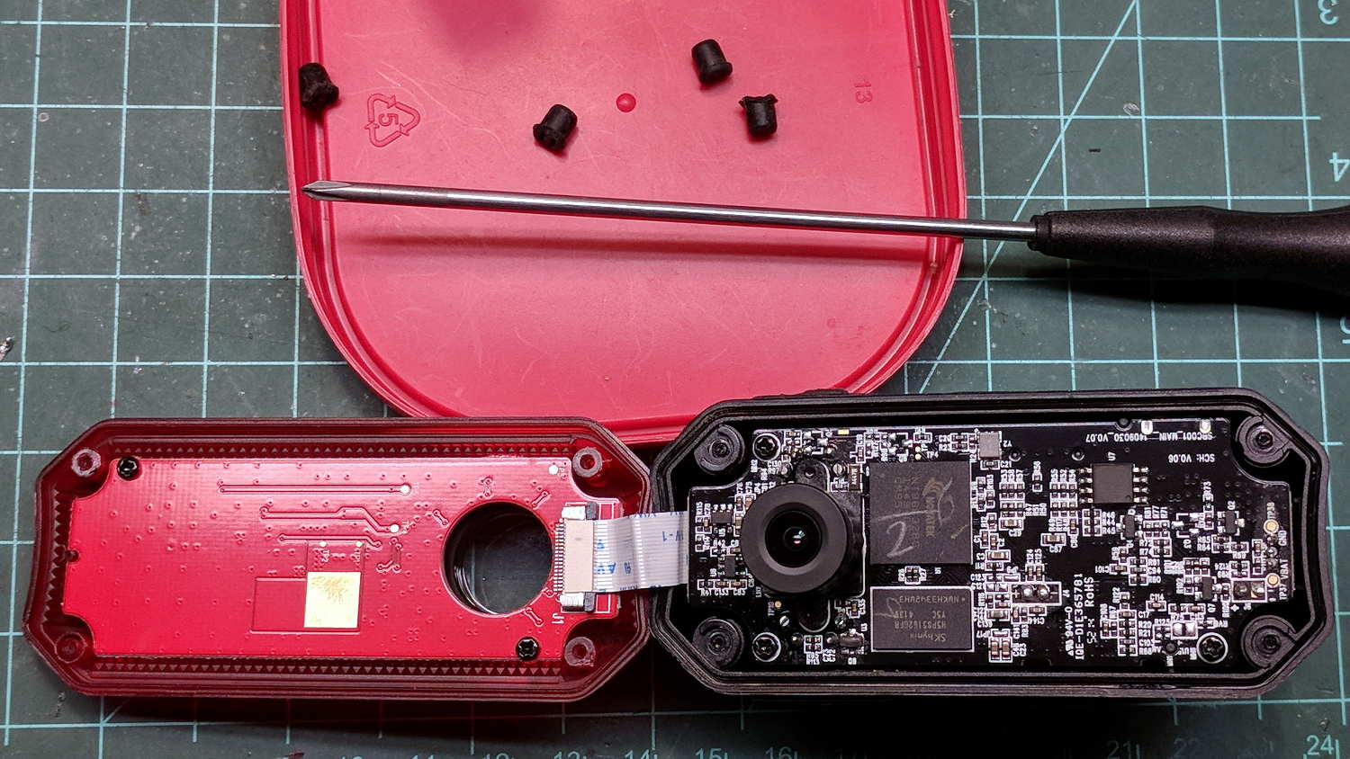
The case pops open, with a ribbon cable between the LEDs and the main circuit board:
Fly6 – Case opened
Pull the ribbon cable latch away from the connector before pulling the cable out.
It’s amazing what you find inside a blinky taillight these days:
Fly6 – PCB Top side
I’m sure there’s a fancy 32 bit RISC computer in the big chip, along with plenty of flash ROM just below it. The clutter over on the right seems to be the power supply. Yeah, it has a camera in addition to blinky LED goodness, plus USB charging, so eight bits of microcontroller aren’t nearly enough.
Note: the case screws are slightly longer than the PCB retaining screws:
Fly6 – Case and PCB Screws
The underside of the PCB has even more teeny parts, along with, mirabile dictu, a battery connector and (most likely) battery charging stuff:
Fly6 – PCB Underside
A plastic piece holds the “Rechargeable Li-Ion Battery Pack” in place:
Fly6 – Battery in place
A strip of gooey adhesive holding the mic and speaker wires in place also glues the battery strap to the case, but it will yield to gentle suasion from a razor knife.
Pause to count ’em up:
Four case screws (longer)
Three PCB screws
Two battery screws
It looked a lot like an ordinary 18650 lithium cell to me and, indeed, it is:
Fly6 – Battery – label
More razor knife work removes the outer shrinkwrap. The cell has a protection PCB under the black cardboard cover:
Fly6 – Battery Protection PCB – on 18650 cell
I don’t know what the yellow wire does:
Fly6 – Battery Protection PCB – wire side
The FS8205A on the left may be an SII S8205 protection IC preset and packaged for a single cell:
Fly6 – Battery Protection PCB – components
After all that, yeah, it’s a dead battery:
Fly6 OEM 18650 – EOL – 2017-12-06
The red curve shows the in-circuit charge state after taking it apart, the green curve comes from charging the bare cell in my NiteCore D4 charger. I have no idea what the nominal current drain might be, but a 0.25 Ah capacity is way under those Tenergy cells.
A new cell-with-tabs should arrive next week, whereupon I’ll solder the protection circuit in place, wrap it up, pop it back in the case, and see how it behaves.
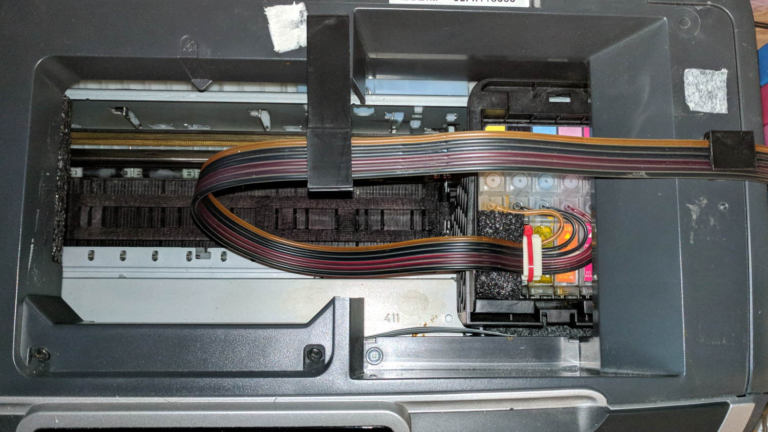
After fixing the yellow ink tube, the Epson R380 printer occasionally gave off a horrible clunk as the tubes slapped around inside the frame. This routing seems much quieter and, as you can see from the marks on the tubes, leaves much less free to flop around:
Epson R380 Printer – CISS tube routing
I cut a small collar (to the left of the white block with the red cable tie) to guide the tubing up over the edge of the ink cartridge holder, with a ramp from the upper edge and raised edges to hold the tubes in place, from a block of black closed-cell foam. It seems perfectly happy to do its job without anything other than the tubes holding it in place atop the cartridges.
There’s also a block of foam filling a gap under the printer’s top frame member (along the far left edge of the picture) to cushion the tubes as they whack against the edge.
So far, so good.
I’ve dumped a few more tanks of waste ink down the drain. When this printer eventually gives up, I’ll get a color laser and move on.
Homing the MPCNC’s Z axis at the bottom end of its travel made no sense, but the Z stage lacks a convenient spot to mount / trigger a switch at the top of its travel, so this sufficed for initial tests & fiddling:
MPCNC – Z min endstop
The EMT rail carrying the switch moves downward, tripping the lever when it hits the MPCNC’s central assembly.
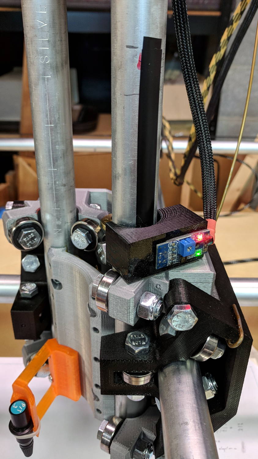
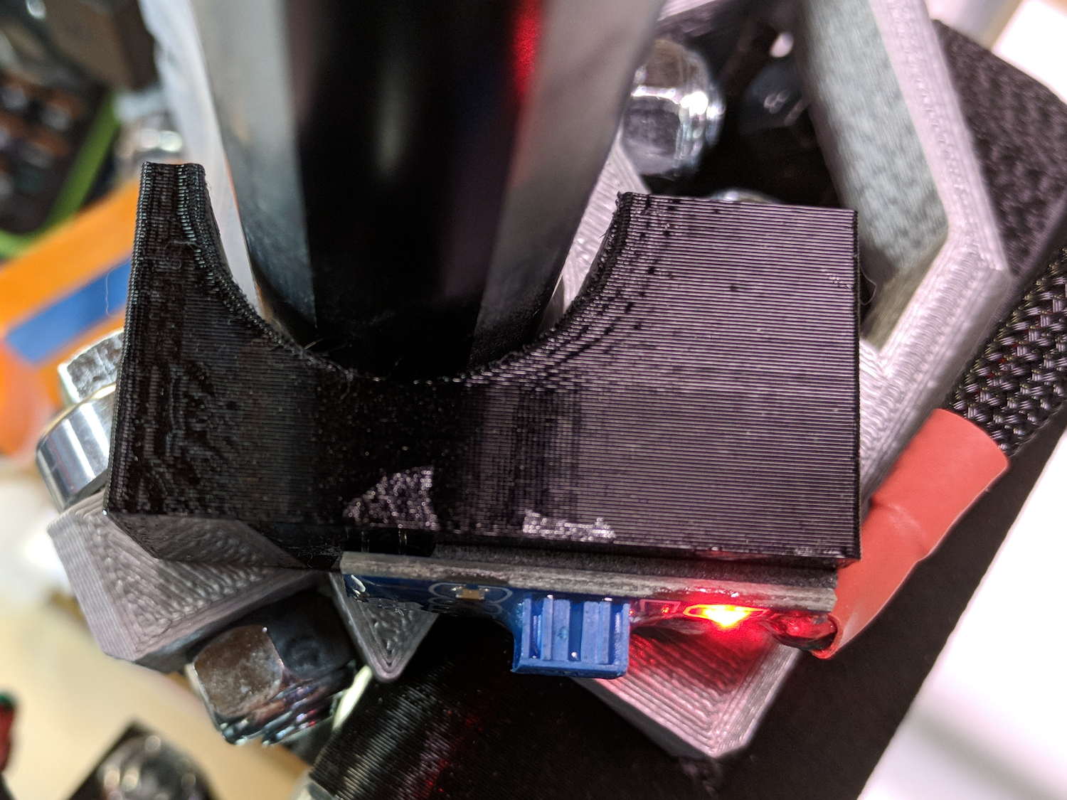
Somewhat to my surprise, a TRCT5000-based optical proximity sensor (harvested from the Kenmore 158 Crash Test Dummy’s corpse) and a strip of black electrical tape work perfectly:
I soldered the wires (harvested from the previous endstop) directly to the PCB, because the pinout isn’t the same and fewer connectors should be better.
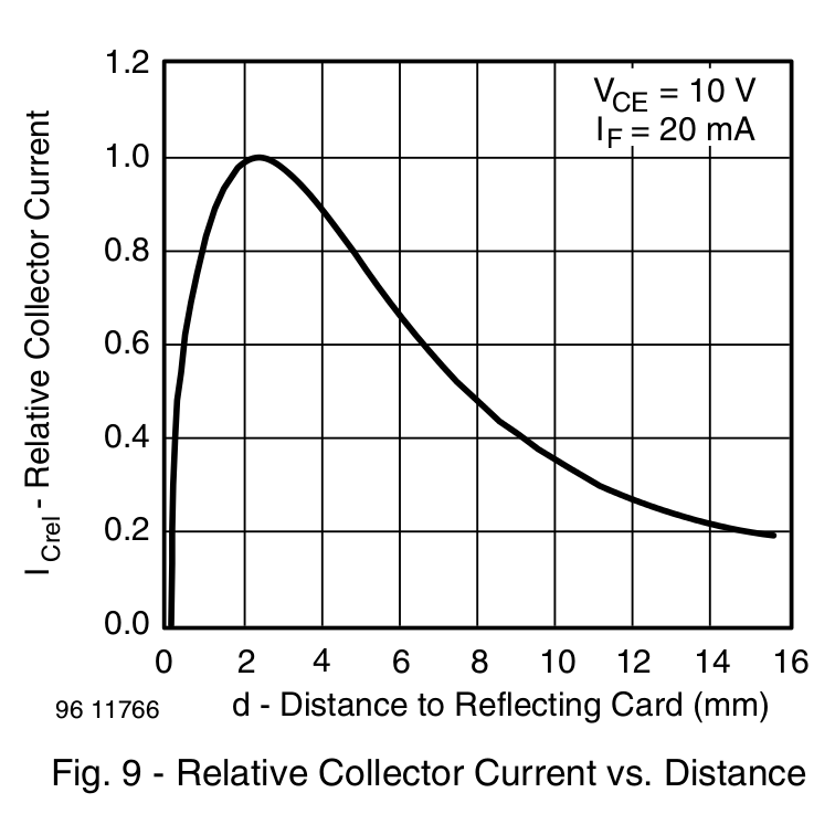
The mount uses black PETG, rather than translucent orange, in hope of IR opacity, and wraps around the EMT rail at (roughly) the 2 mm standoff producing the peak response:
IR Reflective Sensor module – TCRT5000 – response vs distance
In truth, I set the gap by eyeballometric guesstimation to make the entire mount arc sit equidistant from the EMT:
MPCNC – Z Opto Prox Endstop – top view
The mount includes the 2 mm spacing around the EMT OD and puts the sensor tip flush with the arc OD, so it should be pretty close:
TCRT5000 Z Axis Endstop Mount – solid model
A strip of 3M permanent tape, cut to clear the 608 bearings, affixes the mount to the MPCNC’s central assembly. The solid model now includes a midline reference notch, with a height rounded up to the next-highest multiple of 2.0 mm. It needs a loop to anchor the cable.
The blue twiddlepot sets the comparator threshold midway between the response over black tape (incorrectly on = too low) and bare EMT (incorrectly off = too high), in the hope of noise immunity. The range spanned nearly half of the pot rotation, so I think it’s all good.
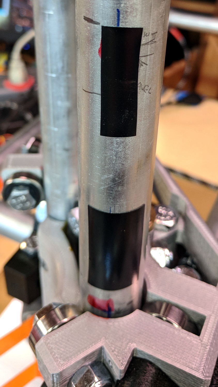
The sensor doesn’t trip when the edge of the tape exactly meets its midline, which meant I had to trim a strip of tape to suit. As part of setting the twiddlepot, I shut off the Z axis motor and laid some test strips on the EMT:
MPCNC – Z Axis Opto Prox Endstop – Test Tape
I spun the leadscrew with one hand, held the sensor with the other, twiddled the trimpot, trimmed the upper and lower ends of the tape, and generally had a fine time. The sensor responds equally well to a half-wide strip of tape (in the upper picture), with the distinct advantage of not encroaching on the 608 bearing tracks.
The GRBL setup now homes Y and Z toward the positive end of their travel, with X still toward the negative end while a set of extension cables remains in transit around the planet.
This file contains hidden or bidirectional Unicode text that may be interpreted or compiled differently than what appears below. To review, open the file in an editor that reveals hidden Unicode characters.
Learn more about bidirectional Unicode characters