Being a big fan of having a CNC machine know where it is, adding endstops (pronounded “home switches” in CNC parlance) to the Mostly Printed CNC axes seemed like a good idea:
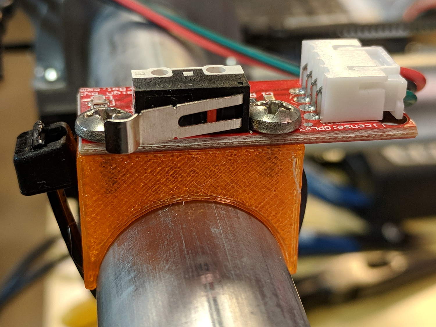
All the mounts I could find fit bare microswitches of various sizes or seemed overly complex & bulky for what they accomplished. Rather than fiddle with screws and nut traps / inserts, a simple cable tie works just fine and makes the whole affair much smaller. Should you think cable ties aren’t secure enough, a strip of double stick tape will assuage your doubts.
A snippet of aluminum sheet moves the switch trip point out beyond the roller’s ball bearing:
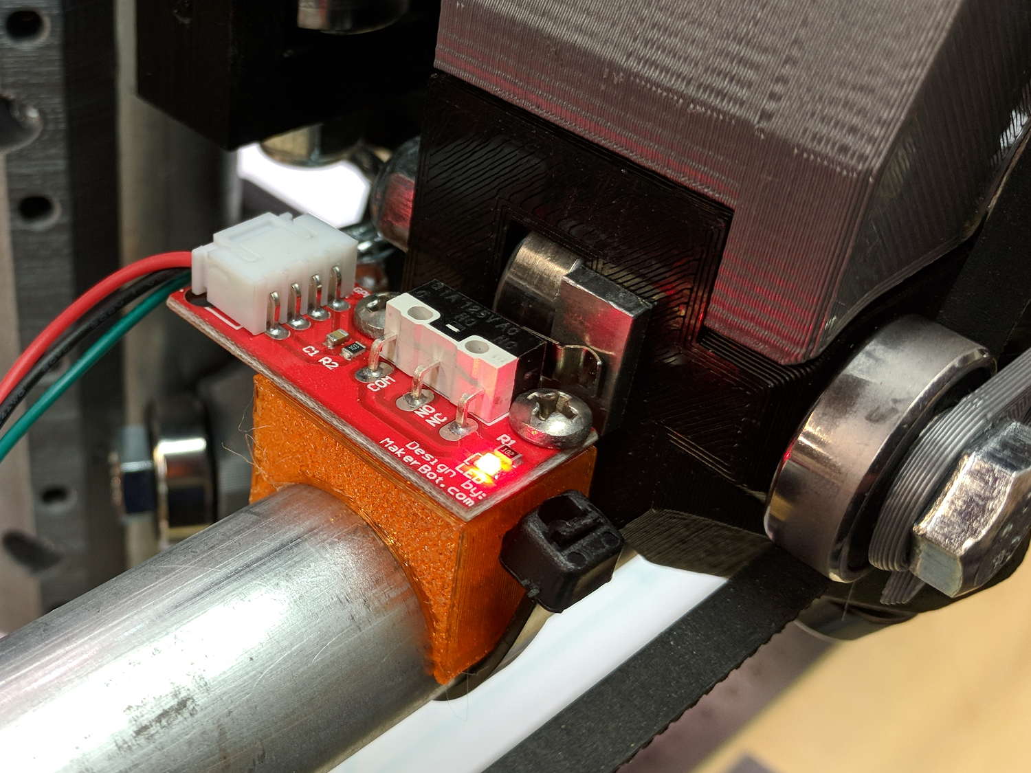
I’m not convinced homing the Z axis at the bottom of its travel is the right thing to do, but it’s a start:

Unlike the stationary X and Y axes, the MPCNC’s Z axis rails move vertically in the middle block assembly; the switch moves downward on the rail until the actuator hits the block.
Perforce, the tooling mounted on the Z axis must stick out below the bottom of the tool carrier, which means the tool will hit the table before the switch hits the block. There should also be a probe input to support tool height setting.
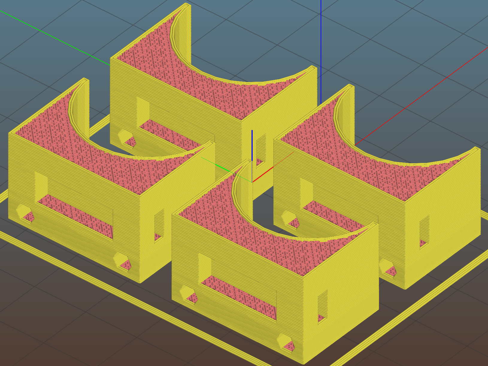
The first mount fit perfectly, so I printed four more in one pass:
All three endstops plug into the RAMPS board, leaving the maximum endstop connections vacant:

Obviously, bare PCBs attached to the rails in mid-air aren’t compatible with milling metal, which I won’t be doing for quite a while. The electronic parts long to be inside enclosures with ventilation and maybe dust filtering, but …
The switches operate in normally open mode, closing when tripped. That’s backwards, of course, and defined to be completely irrelevant in the current context.
Seen from a high level, these switches set the absolute “machine coordinate system” origin, so the firmware travel limits can take effect. Marlin knows nothing about coordinate systems, but GRBL does: it can touch off to a fixture origin and generally do the right thing.
The OpenSCAD source code as a GitHub Gist:
| // Tour Easy Fairing Endstop Mount for Makerbot PCB | |
| // Ed Nisley KE4ZNU – 2017-11-07 | |
| /* [Build Options] */ | |
| Layout = "Build"; // [Build, Show, Block] | |
| Section = false; // show internal details | |
| /* [Extrusion] */ | |
| ThreadThick = 0.25; // [0.20, 0.25] | |
| ThreadWidth = 0.40; // [0.40] | |
| function IntegerMultiple(Size,Unit) = Unit * ceil(Size / Unit); | |
| /* [Hidden] */ | |
| Protrusion = 0.01; // [0.01, 0.1] | |
| HoleWindage = 0.2; | |
| ID = 0; | |
| OD = 1; | |
| LENGTH = 2; | |
| /* [Sizes] */ | |
| RailOD = 23.5; | |
| Screw = [3.4,6.8,8.0]; // thread dia, head OD, screw length | |
| HoleOffset = [2.5,19.0/2]; // PCB mounting holes from PCB edge, rail center | |
| SwitchClear = [6.0,15,3.0]; // clearance around switch pins | |
| SwitchOffset = [6.0,0]; // center of switch from holes | |
| Strap = [5.5,50,2.0]; // nylon strap securing block to rail | |
| Block = [16.4,26.0,RailOD/2 + SwitchClear[2] + Strap[2] + 6*ThreadThick]; // basic block shape | |
| //- Adjust hole diameter to make the size come out right | |
| module PolyCyl(Dia,Height,ForceSides=0) { // based on nophead's polyholes | |
| Sides = (ForceSides != 0) ? ForceSides : (ceil(Dia) + 2); | |
| FixDia = Dia / cos(180/Sides); | |
| cylinder(r=(FixDia + HoleWindage)/2,h=Height,$fn=Sides); | |
| } | |
| //- Shapes | |
| module PCBBlock() { | |
| difference() { | |
| cube(Block,center=true); | |
| translate([(SwitchOffset[0] + HoleOffset[0] – Block[0]/2),SwitchOffset[1],(Block[2] – SwitchClear[2] + Protrusion)/2]) | |
| cube(SwitchClear + [0,0,Protrusion],center=true); | |
| for (j=[-1,1]) | |
| translate([HoleOffset[0] – Block[0]/2,j*HoleOffset[1],(Block[2]/2 – Screw[LENGTH])]) | |
| rotate(180/6) | |
| if (false) // true = loose fit | |
| PolyCyl(Screw[ID],Screw[LENGTH] + Protrusion,6); | |
| else | |
| cylinder(d=Screw[ID],h=Screw[LENGTH] + Protrusion,$fn=6); | |
| translate([0,0,Block[2]/2 – SwitchClear[2] – Strap[2]/2 – 3*ThreadThick]) | |
| cube(Strap,center=true); | |
| if (Section) | |
| translate([Block[0]/2,0,0]) | |
| cube(Block + [0,2*Protrusion,2*Protrusion],center=true); | |
| } | |
| } | |
| module Mount() { | |
| difference() { | |
| translate([0,0,Block[2]/2]) | |
| PCBBlock(); | |
| rotate([0,90,0]) | |
| cylinder(d=RailOD,h=3*Block[0],center=true); | |
| } | |
| } | |
| //- Build things | |
| if (Layout == "Show") { | |
| Mount(); | |
| color("Yellow",0.5) | |
| rotate([0,90,0]) | |
| cylinder(d=RailOD,h=3*Block[0],center=true); | |
| } | |
| if (Layout == "Block") | |
| PCBBlock(); | |
| if (Layout == "Build") | |
| translate([0,0,Block[2]/2]) | |
| rotate([0,-90,0]) | |
| Mount(); |

Comments
4 responses to “Mostly Printed CNC: Endstop Mount”
I’d be tempted to leave a recess in the mounting block to accept the end of the cable tie so it doesn’t stick out, but that may be getting too fiddly.
I thought about a little recess, then came to my senses. At least I’m trimming the loose end of the cable tie, per the MPCNC requirements. [grin]
Maybe in Version 1.1, with provision for something like a pill-bottle debris shield.
[…] being nothing like a new problem to take your mind off all your old problems, now there’s a cable tie […]
[…] but the Z stage lacks a convenient spot to mount / trigger a switch at the top of its travel, so this sufficed for initial tests & […]