Ed Nisley's Blog: Shop notes, electronics, firmware, machinery, 3D printing, laser cuttery, and curiosities. Contents: 100% human thinking, 0% AI slop.
Three times is enemy action, but we’re not there yet. I was willing to believe something I’d done had killed both of the radios, even though it seemed unlikely for them to last five years and fail almost simultaneously.
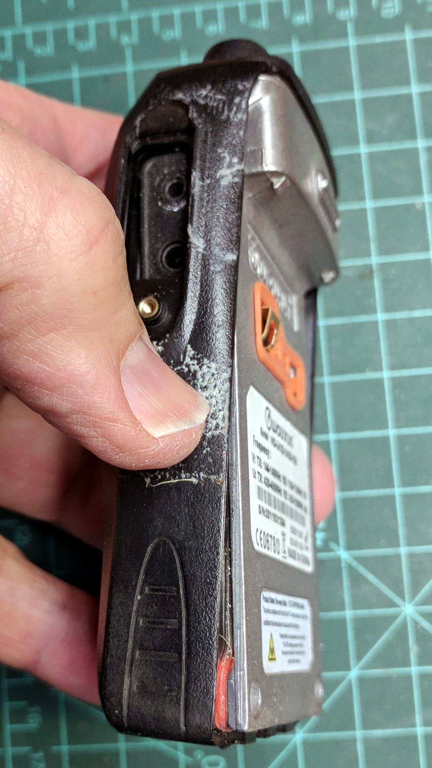
So I dismantled this one to see what’s inside. Pull off both knobs, remove the two screws at the bottom of the battery compartment, pry gently with a small screwdriver, and the whole PCB pulls out:
Wouxun KG-UV3D – disassembly
A bit more prying separates the big pieces:
Wouxun KG-UV3D – interior
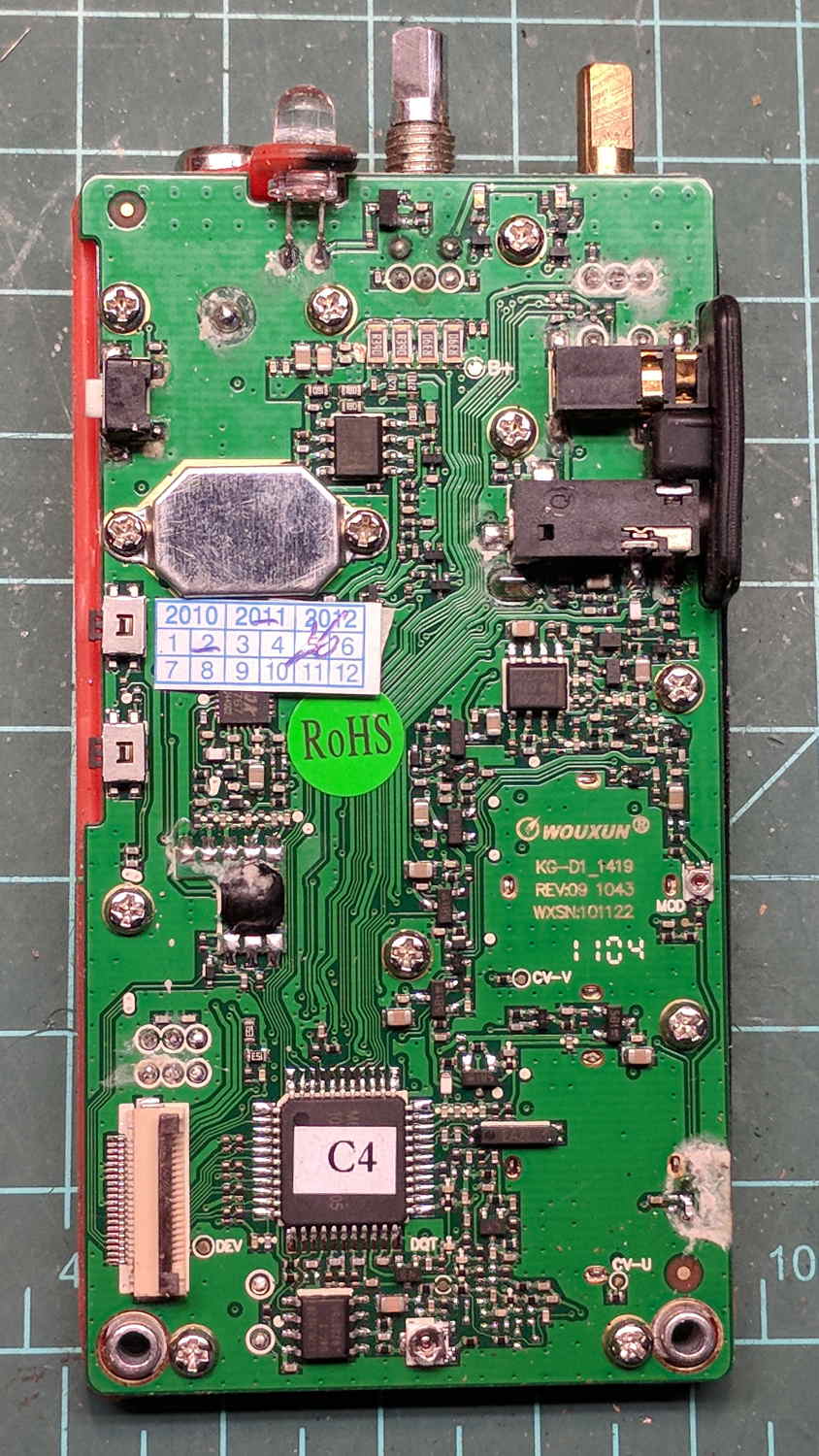
Looking closely at the main PCB showed some problems I definitely didn’t cause:
Wouxun KG-UV3D – PCB overview
Although it’s been riding around on my bike, the white blotches on the PCB came from inadequate flux removal after hand soldering.
A collection of images taken through the microscope reveals the problems:
This slideshow requires JavaScript.
I swabbed off the crud with denatured alcohol to no avail. The bottom side of the PCB has even more components and, I’m sure, even more crud, but I didn’t bother removing all the screws required to expose it, nor did I dismantle the other failed HT.
I doubt Wouxun’s QC improved over the last few years, which means the two replacement KG-UV3D radios I just bought are already on their last legs, despite my paying top dollar to the same reputable source that sold me the first pair.
We’ll be ready for new radios on new bikes by the time these fail.
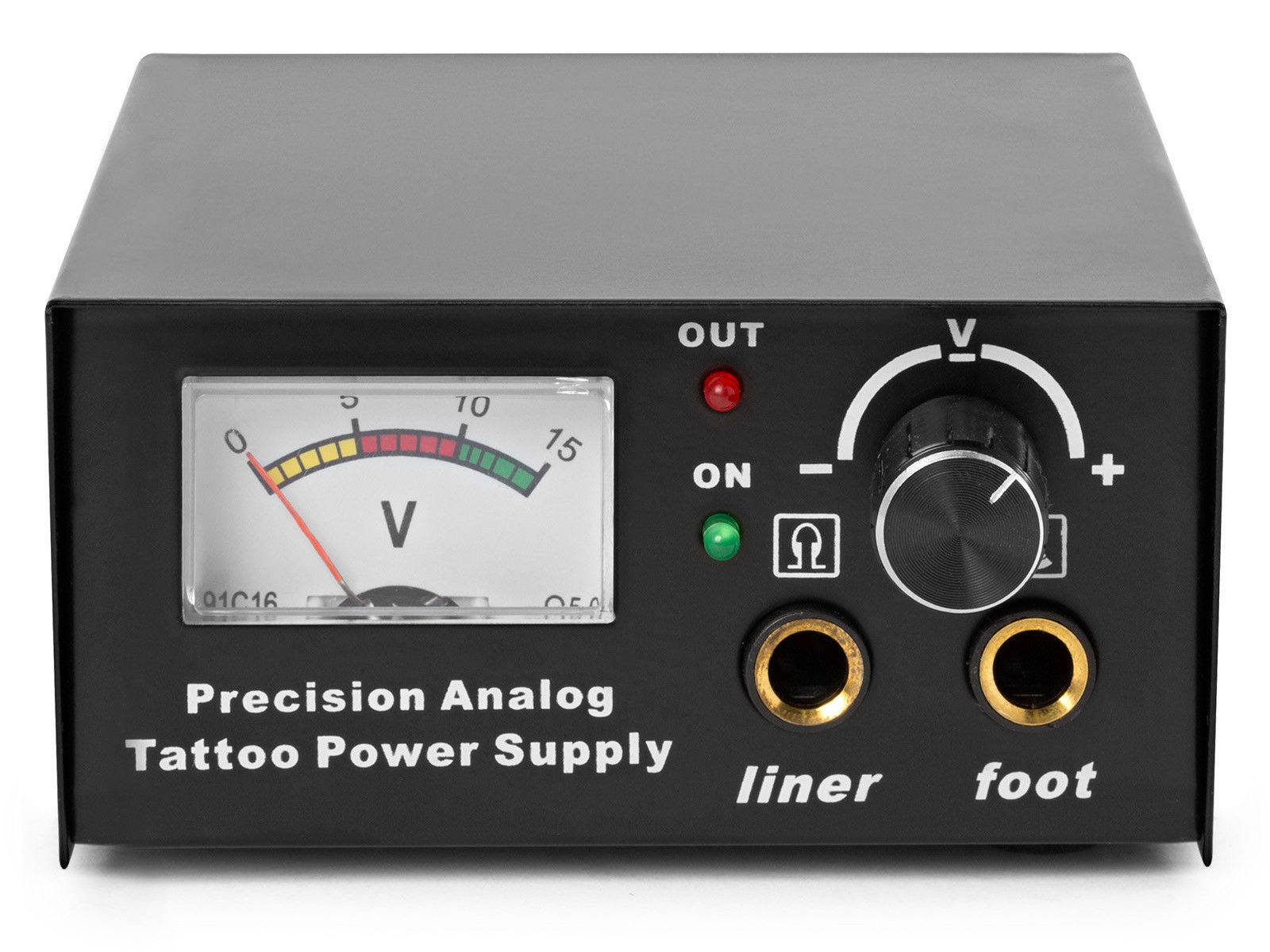
The idea behind this gadget surfaced while I was looking for something else and, although the front panel makes my skin crawl, it’s just an adjustable DC power supply:
Let’s say it has the potential to be a DC power supply, although we might quibble about the “Precision” part.
As delivered, it’s a deathtrap. Of course, it’s not UL listed and I didn’t expect it to be.
How many lethal problems do you see?
Tattoo power supply – original AC wiring
For starters, it has a three-wire AC line cord with the green-and-yellow conductor chopped off flush with the outer insulation inside the heatshrink tubing just behind the transformer:
Tattoo power supply – ungrounded AC line
The blue wire is AC neutral, but it really shouldn’t be connected to the finger-reachable outer fuse terminal.
The brown wire is AC line, which goes directly to one power switch terminal. In the event of a hot wiring fault, an unfused conductor touching the case will test the GFI you should have on your bench wiring.
The AC line cord uses some mysterious copper-colored metallic substance that’s about as stiff as music wire:
Tattoo power supply – stiff AC wire
The strands cannot be twisted together like ordinary copper wire, although they can be soldered. They may be copper-plated aluminum, because a magnet ignores them.
After soldering the strands together, they snap when bent:
Tattoo power supply – soldered broken AC wire
Generous strain relief is not just a good idea, it’s mandatory.
After some Quality Shop Time, the ground wire now connects to the case through the transformer’s rear mounting screw, the neutral AC wire connects to the transformer, the hot AC wire goes to the tip of the line fuse, and the fuse cap terminal goes to the switch:
Tattoo power supply – AC line rewiring
I relocated the white LED to the middle of the meter, where it looks a bit less weird:
Tattoo power supply – revised front panel
I have no idea what “Porket indicate” might mean. Perhaps “Precision indicator”?
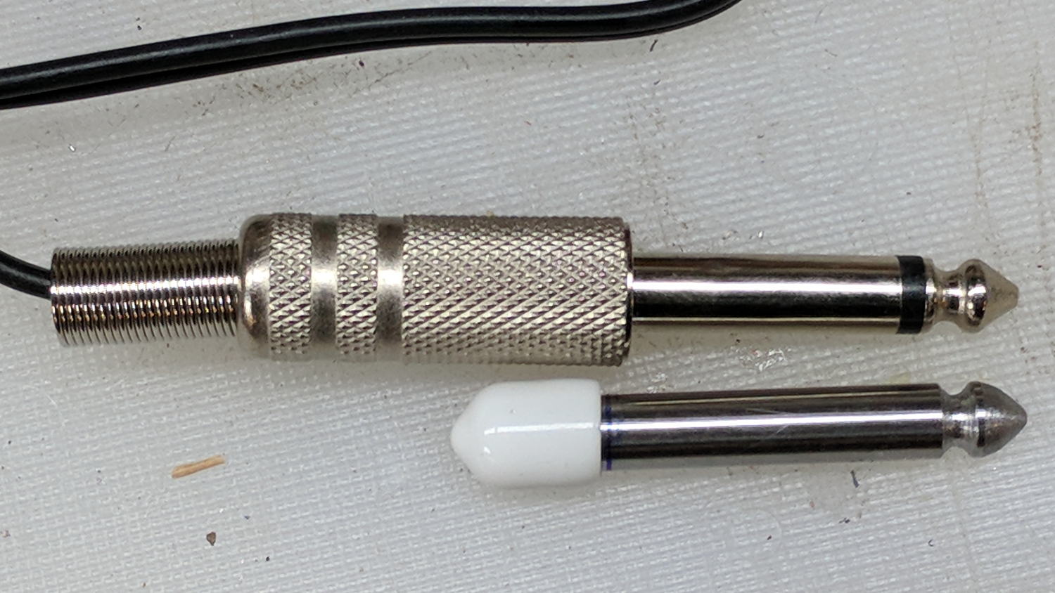
The right 1/4 inch jack, labeled “Foot”, normally goes to a foot switch you don’t need for a bench power supply, so I converted a length of drill rod into a dummy plug to short the jack contacts:
Tattoo power supply – dummy switch plug
The tip comes from a bit of lathe and file work and the white cap comes from a bag of wire shelf hardware.
A genuine hologram sticker (!) on the back panel proclaims “1.5 – 15 VDC 2 A”, which seemed optimistic. Some fiddling with power resistors suggests tattoo liners (I learned a new word!) don’t draw much current:
4 V @ 1 A
8 V @ 800 mA
10 V @ 600 mA
It can reach a bit over 18 V (pegging the meter) at lower current, so it’s Good Enough for small projects with un-fussy power requirements.
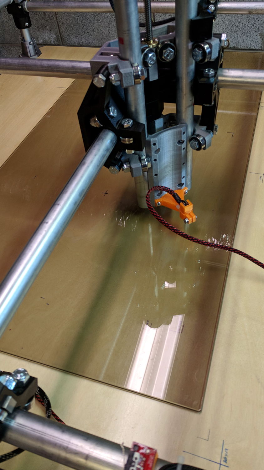
When I wired up the MPCNC’s tool length probe, I planned to reinforce the wiring with a dab of epoxy. What I didn’t notice in my enthusiasm, alas, was the opening from the rear to the front in each pin slot:
Epoxied connector – rear
Which let the epoxy flow completely through the connector:
Epoxied connector – front
So I cut the mess off and applied heatstink tubing on each wire, just like I should have in the first place.
Now you know the rest of the story …
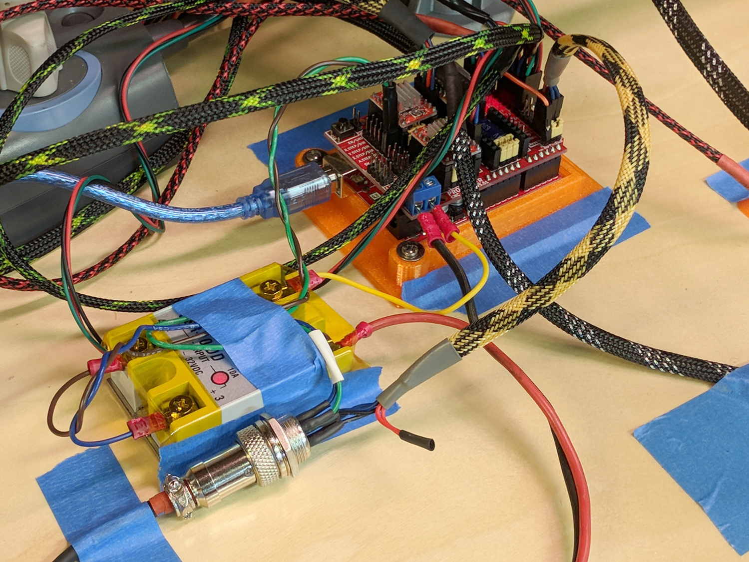
I really dislike pin headers as cable connectors, but that’s what the Protoneer CNC board uses:
MPCNC – Protoneer Wiring – SSR
It’ll be Good Enough if I don’t do anything else particularly stupid.
The recent bitter cold and gusty winds swirled a dry snowfall around our back patio, where it clung to the (otherwise invisible) spider silk strands on the cedar shakes:
Although I repaired the spout a while ago, those water bottles were never satisfactory and saw very little use. A recent cabinet cleanout showed the “stainless steel” has passed beyond its best-used-by date:
Stainless steel water bottle – rust
With no regard for whether the patient would survive the operation, I peeled off its rubber foot and applied the Lesser Hammer:
Stainless steel water bottle – insulation
The “insulation” seems to be a rigid urethane-like foam disk few millimeters thick on the bottom of the interior flask, with good old air around the sides.
The bottles never worked very well and now we know why.
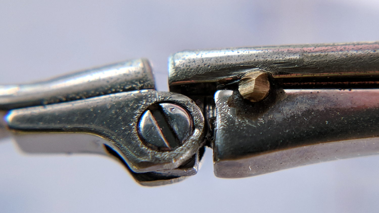
After three years, the temple screw on Mary’s oldest and most-battered “reading” glasses worked loose. A dab of low-strength Loctite should hold it in place forever more:
Reading glasses temple repair
That brass stake pin certainly adds a Steampunk flair to the proceedings …
The first height map looks like a mountain sproinged right up through the glass:
ProbeArray-Glass-50
More red-ish means increasing height, more blue-ish means increasing depth, although you can only see the negative signs along the left edge.
The Z axis leadscrew produces 400 step/mm for a “resolution” of 0.0025 mm. The bCNC map rounds to three places, which makes perfect sense to me; I doubt the absolute accuracy is any better than 0.1 mm on a good day with fair skies and a tailwind.
The peak of the mountain rises 0.35 mm above the terrain around it, so it barely counts as a minor distortion in the glass sheet. Overall, however, there’s a 0.6 mm difference from peak to valley, which would be enough to mess up a rigidly held pen tip pretty badly if you assumed the glass was perfectly flat and precisely aligned.
Rotating the glass around the X axis shows a matching, albeit shallower, dent on the other side:
ProbeArray-Glass-flip-50-2018-01-05
For all its crudity, the probe seems to be returning reasonable results.
The obvious question: does it return consistent results?