Ed Nisley's Blog: Shop notes, electronics, firmware, machinery, 3D printing, laser cuttery, and curiosities. Contents: 100% human thinking, 0% AI slop.
You’re looking downward from the edge of the communal meal countertop at the power and network cable ports in the floor. The cables snake into the counter legs and emerge at the countertop to provide AC power, USB charging, and wired network ports in addition to ubiquitous WiFi: all the conveniences of modern dining.
Alas, down at floor level, the poor cables get kicked against the edge of their cover plates, bent with no strain relief, and seem jammed under the sharp edges of the leg extrusions. I expect the connectors below the hatches also endure a nightly bath of gritty water, with bonus salt during the winter months.
And, yes, the AC power plug sits halfway out of its socket, with the blades exposed.
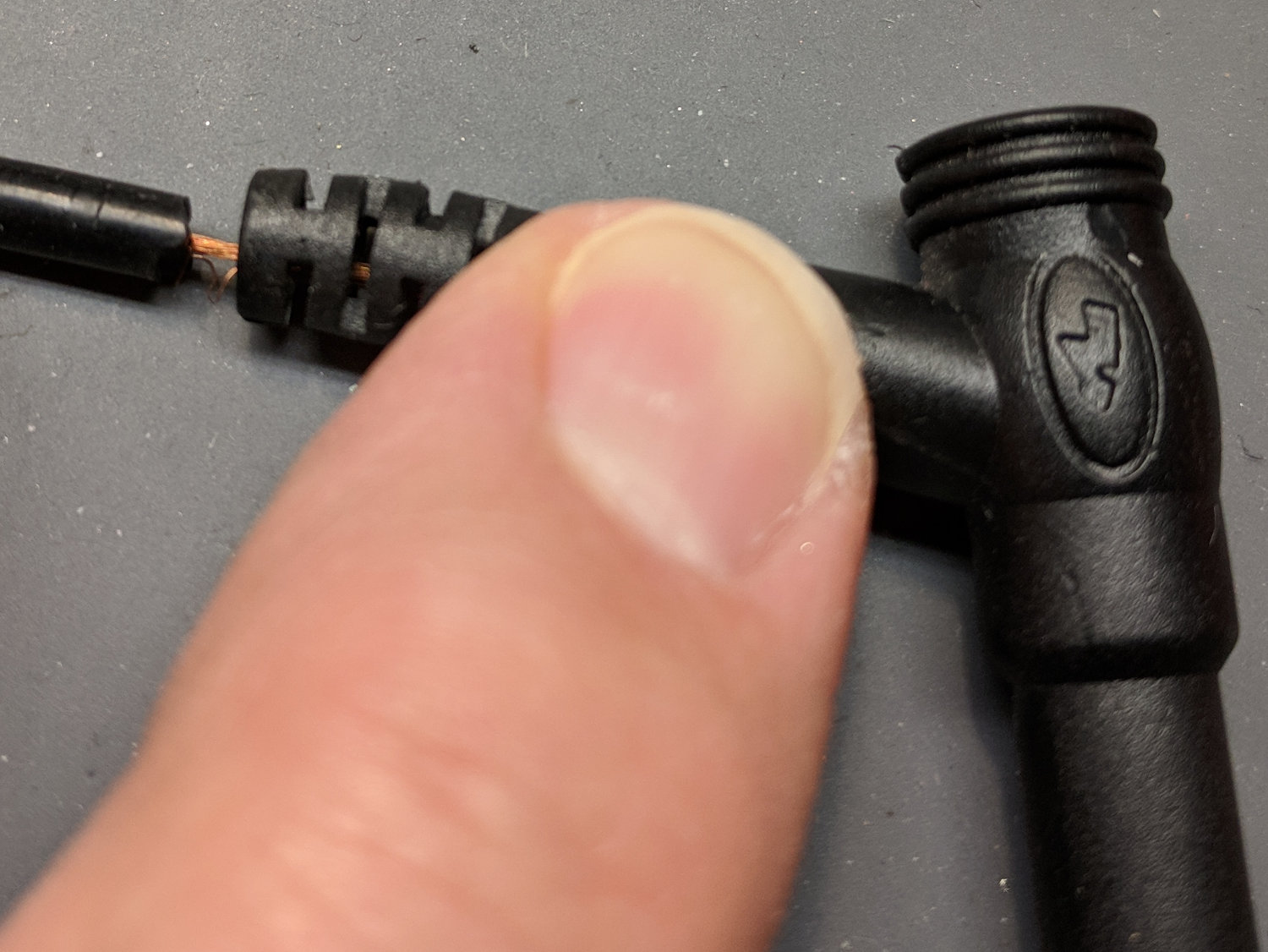
A reasonably good silicone-wire multimeter probe set arrived last spring and has worked well enough (I thought, anyhow) for the usual voltage measurements, but recently failed while measuring a small current. We all know how this will turn out, but the details may be of some interest.
Measuring the resistance from tip to plug located the fault to the black probe, after which I poked a pin through the insulation near the plug:
Multimeter probe – diagnosis
The two leads near the bottom go to my shiny Siglent bench multimeter. Despite their similarity to the failed probes, I’m pretty sure Siglent has better QC (well, mostly).
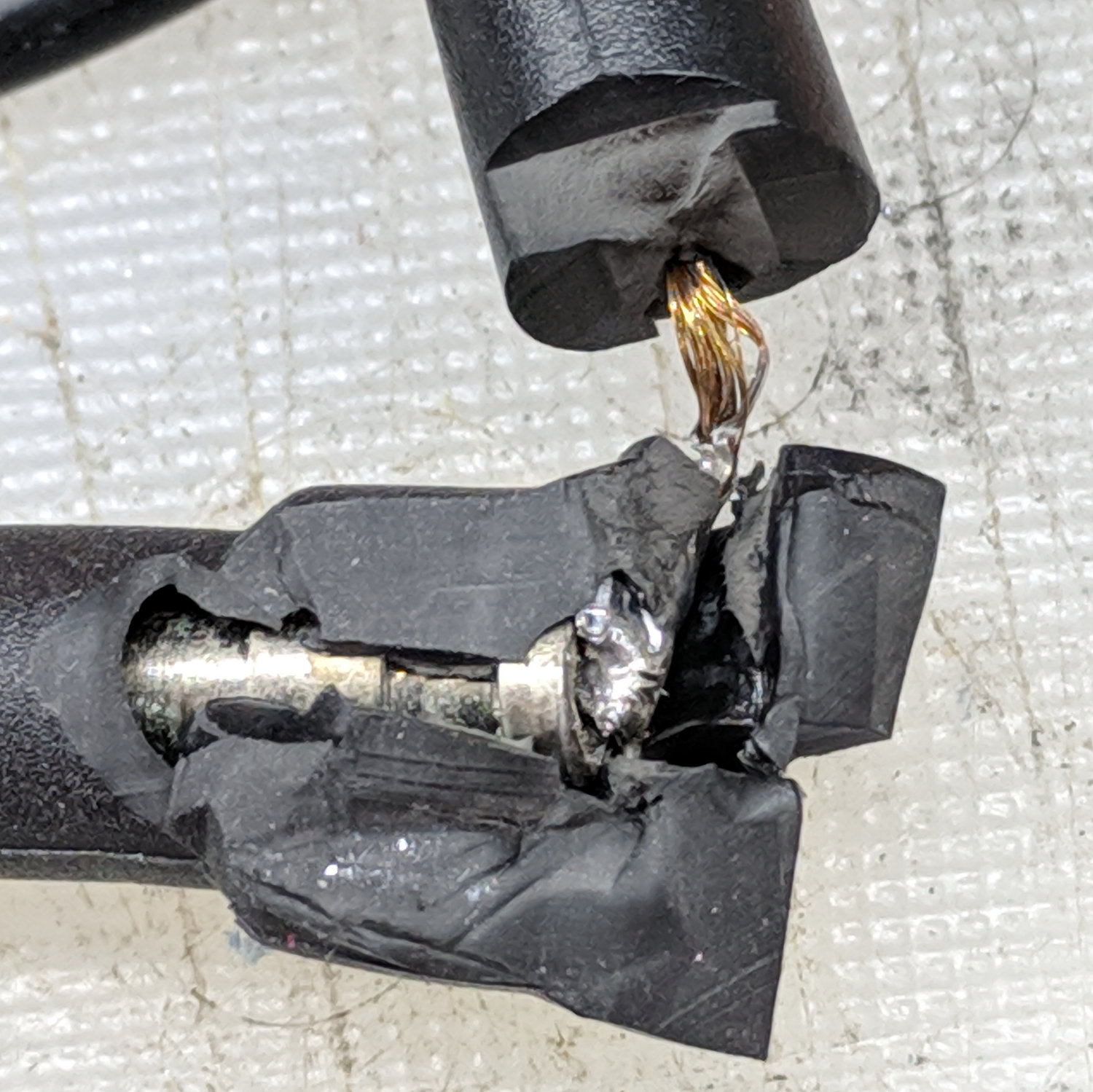
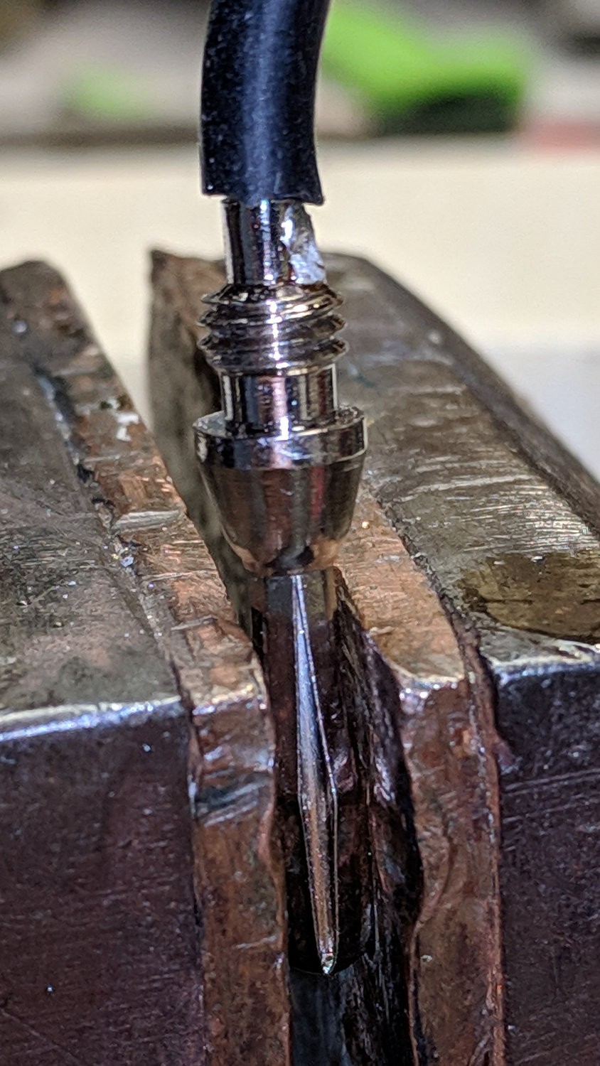
The probe’s resistance was near zero from the tip (offscreen to the left) to the pin and megohms from pin to plug (on the right). Figuring the wire worked loose, I pulled it away from the plug:
Multimeter probe – disassembly 1
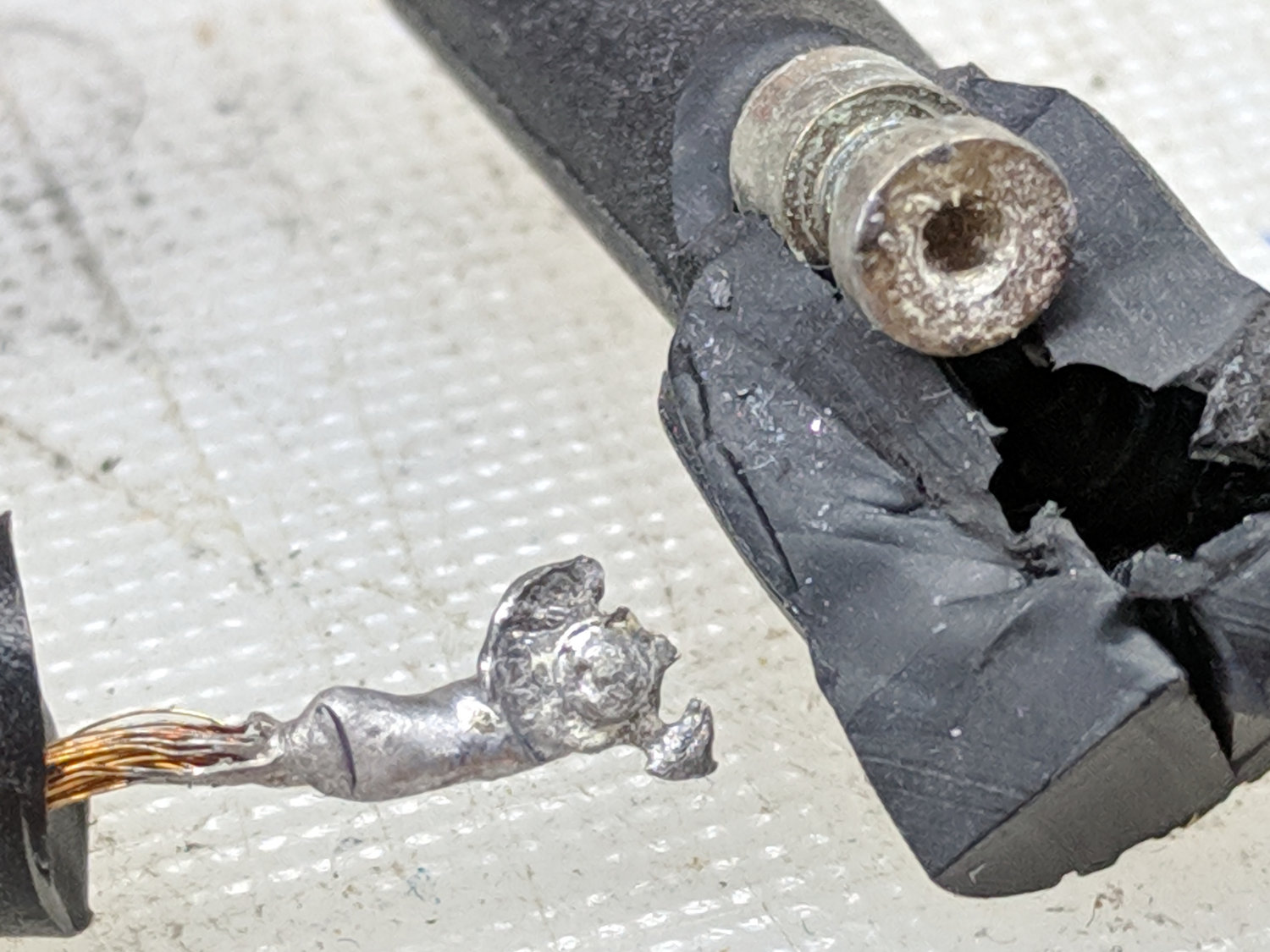
Huh.
Although I wouldn’t have trusted those probes anywhere near their alleged 1 kV rating, seeing that exposed copper-like substance was disconcerting.
Hacking off the strain relief bushing around the wire got closer to the fault:
A discussion of random numbers at Squidwrench brought those gamma ray detectors to the top of the heap, with the observation I probably needed a few more Darlington transistors:
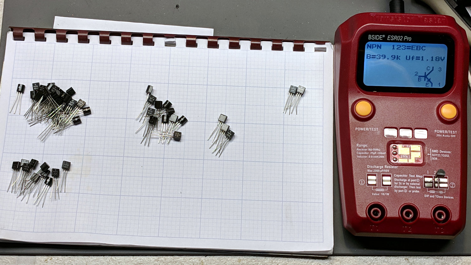
Darlington transistor – hFE sorting
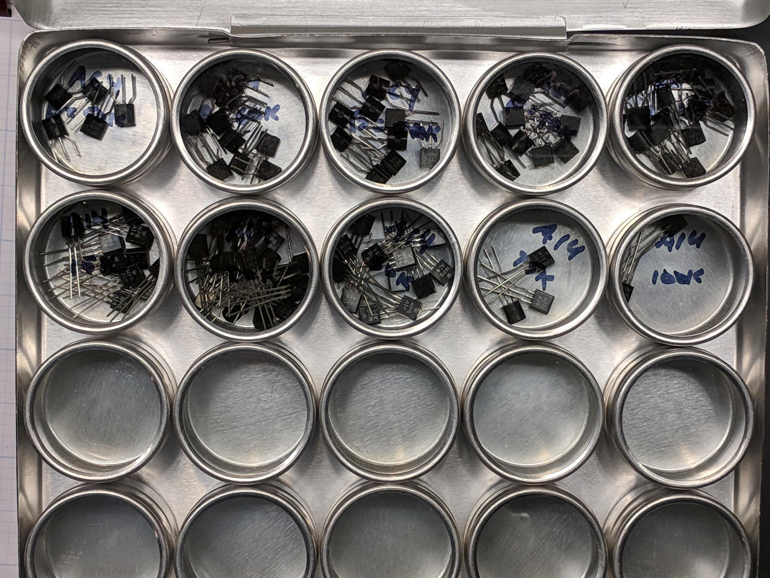
Sorting two lots of 50 transistors by gain kept me out of trouble for a while:
Darlington transistors – sorted
Those are MPSA14 NPN and MPSA64 PNP transistors, with DC gains ranging from around the spec’s minimum 10 k spec all the way up to well over 100 k.
The yellow trace shows the booster output voltage is 9 VDC, as set by the twiddlepot, and doesn’t vary much under load. It has 200 mV ripple at 220 kHz, the booster’s switching frequency, which doesn’t induce any meaningful noise on the scope’s display, because it’s well outside the display bandwidth and well inside the voltage spec.
The current traces are 100 mA/div from Tek Hall effect probes. The green trace is battery current to the booster, varying from 200 to 300 mA, averaging 250 mA. The cyan trace is DSO150 current from the booster, 75 mA min, 200 mA max, averaging 100 mA.
The battery current is 2.5 × the scope current, the battery voltage is 1/2.5 × the scope voltage, and all is right with the world.
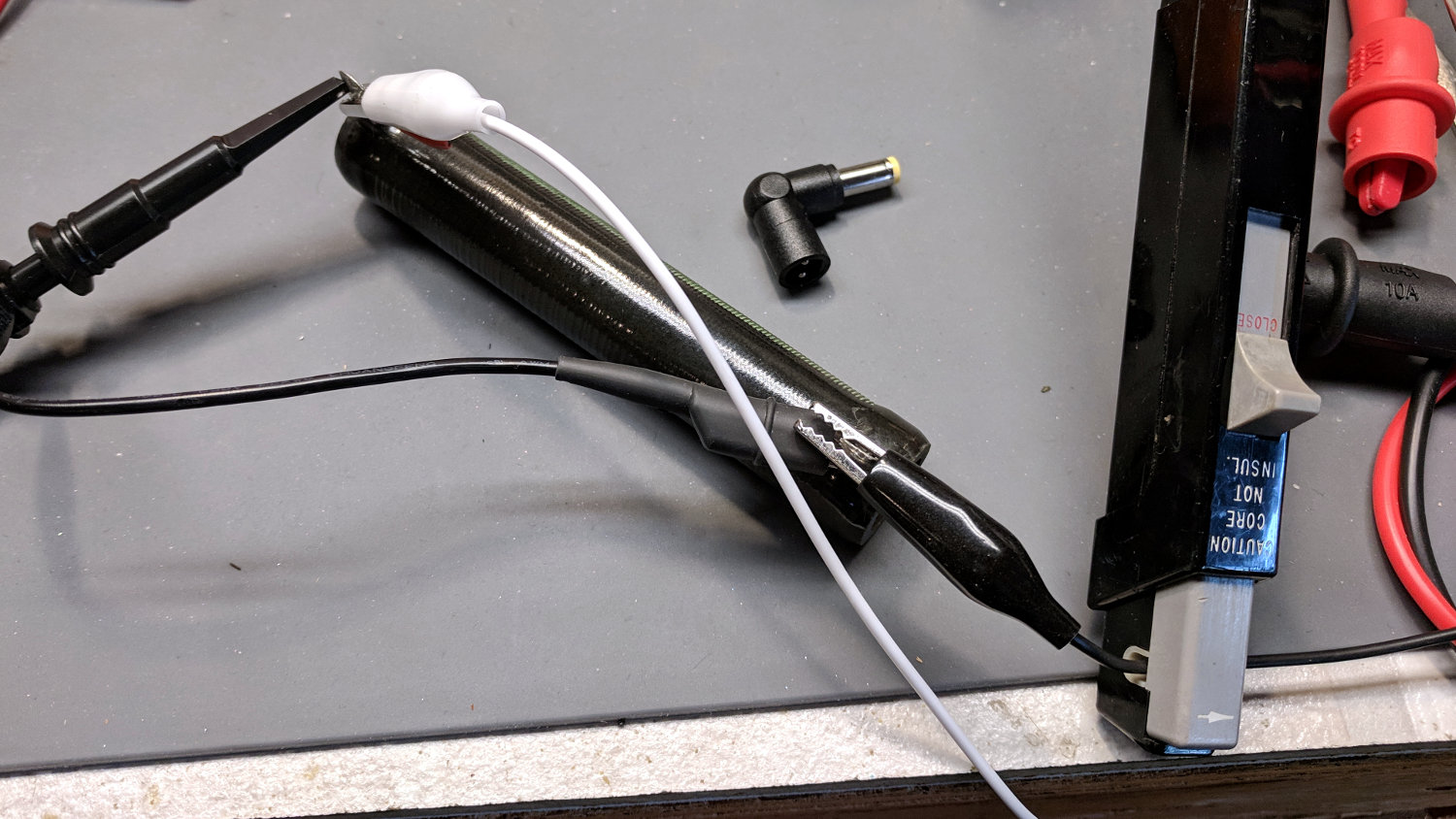
Two multi-output wall warts (Powseed and Leapara, for whatever that’s worth) with a bag of right-angle tips just arrived and I gimmicked up a connection directly to the output:
Powseed multi-voltage supply – hack-job test connection
Which went to a 100 Ω dummy load drawing about the same current as the DSO150:
Power supply load test – 100 ohm resistor
Both seem to work OK, albeit with plenty of spiky noise:
PowSeed Multi-Voltage Wart – 9 V 100 mA-div
Much to my surprise, there’s no visible noise on the DSO150 display, surely because the scope’s bandwidth is nowhere near wide enough to grow that kind of grass.
A power supply like that would convert the DSO150 into a bench instrument suitable for low frequency circuitry.
At this late date, the RepRap site has a much better G-Code reference, at least for the weird and wonderful assortment of 3D printer commands.
Given that I’m at best a secondary reference for Toyota Sienna ABS trouble codes, things must be getting grim out there in the minivan crowd.
And, as always, houses (and especially plumbing) are trouble!
As for everything else, well, it’s just me and my shop notes …
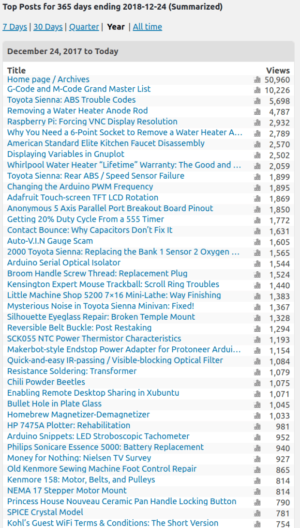
WordPress reports 101 k ad impressions per month for 24.6 k “page views”, suggesting most folks see four ads per page. If you’re not using an ad blocker, start now!
Those seem to be the most aggressive (and thus highly desirable to advertisers) video ads, because WordPress pays me a whopping 8¢ per kilo-impression; a few percent of the Youtube rate. The numbers are dropping, though, suggesting ads will never push me into the ranks of the thousandaires.
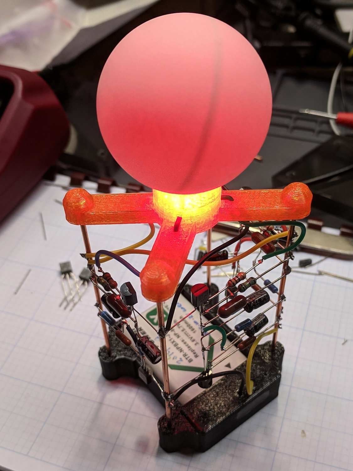
The blue LED works, too, but I didn’t catch any of those blinks.
The spider should be done in black PETG, just like the battery holder, but I didn’t realize which filament was running until too late. Even the blue LED lights up the orange spider just fine!
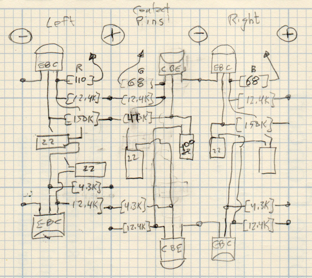
The circuitry behind (well, below) the RGB LED Radome consists of three copies of the original multivibrator, with mirror image layouts to match the wire struts:
RGB LED Schematic – NPN transistors
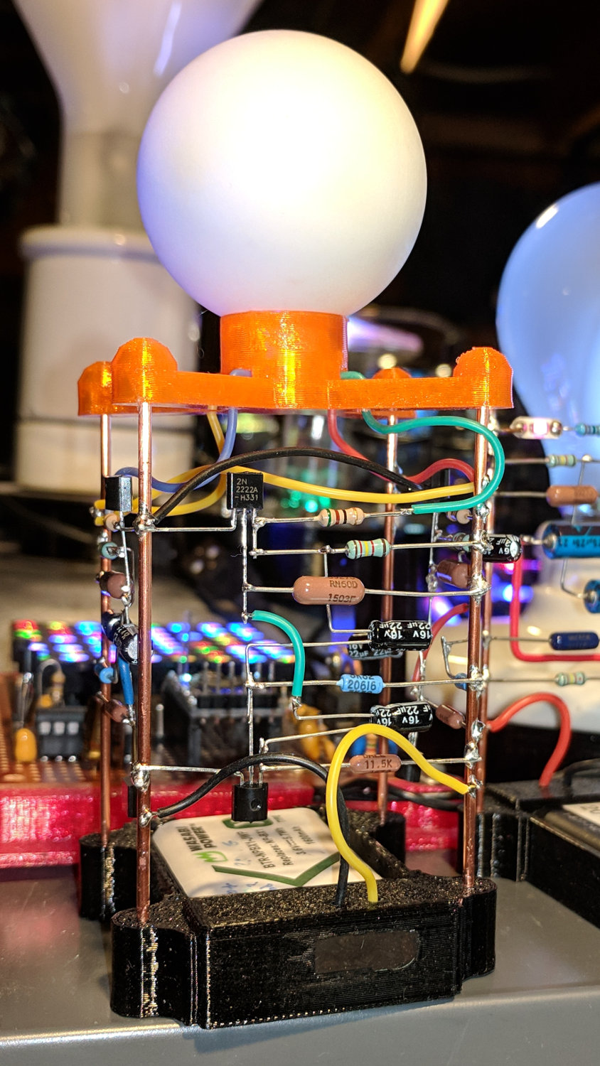
The solder joints adhere to exactly none of the usual good practices:
Astable RGB LED – assembled
The simulation matches the actual blink times reasonably well:
Astable – 2N2222 cap voltages
It’s unpleasantly frenetic in real life. The next version must have much much longer time constants.
Unfortunately, the simulation also confirms my suspicion that I’ve been abusing the electrolytic capacitors with reverse-polarity waveforms. I suspect it doesn’t really matter too much, as the maximum voltage in either direction remains under a volt at very low currents, but it’s the principle of the thing.
Soooo, lengthening the time constants by increasing the capacitances seems like a Bad Idea.
Alas, increasing the resistors by an order of magnitude won’t work, either, because (despite appearances) the whole thing sits right on the hairy edge of not working. As the battery discharges toward its 2.5 V cutoff level, the currents drop and the circuitry becomes increasingly sensitive to touch. After a day or two, one of the LEDs will jam solidly on, while the others continue to blink merrily away. Removing and reinstalling the battery will sometimes resume proper operation, but it’s definitely not stable enough for production use.
Which makes a MOSFET astable multivibrator seem like a Good Idea.
One could achieve the same visible result with a few cents of microcontroller and a dab of software, but most of the charm comes from its analog nature and all those visible components.
You can find anything on eBay (clicky for more dots):
ZVNL110A MOSFET – kilobuck eBay pricing
The key information:
ZVNL110A MOSFET – kilobuck eBay pricing – detail
For that price, I’d expect in-person hand delivery.
Stipulated: ZVNL110A MOSFETs aren’t in production and we’re buying from diminishing inventory, but (as of late December 2018) they’re still available for under a buck apiece in small quantities.