It lights up just like it should:

In colors:
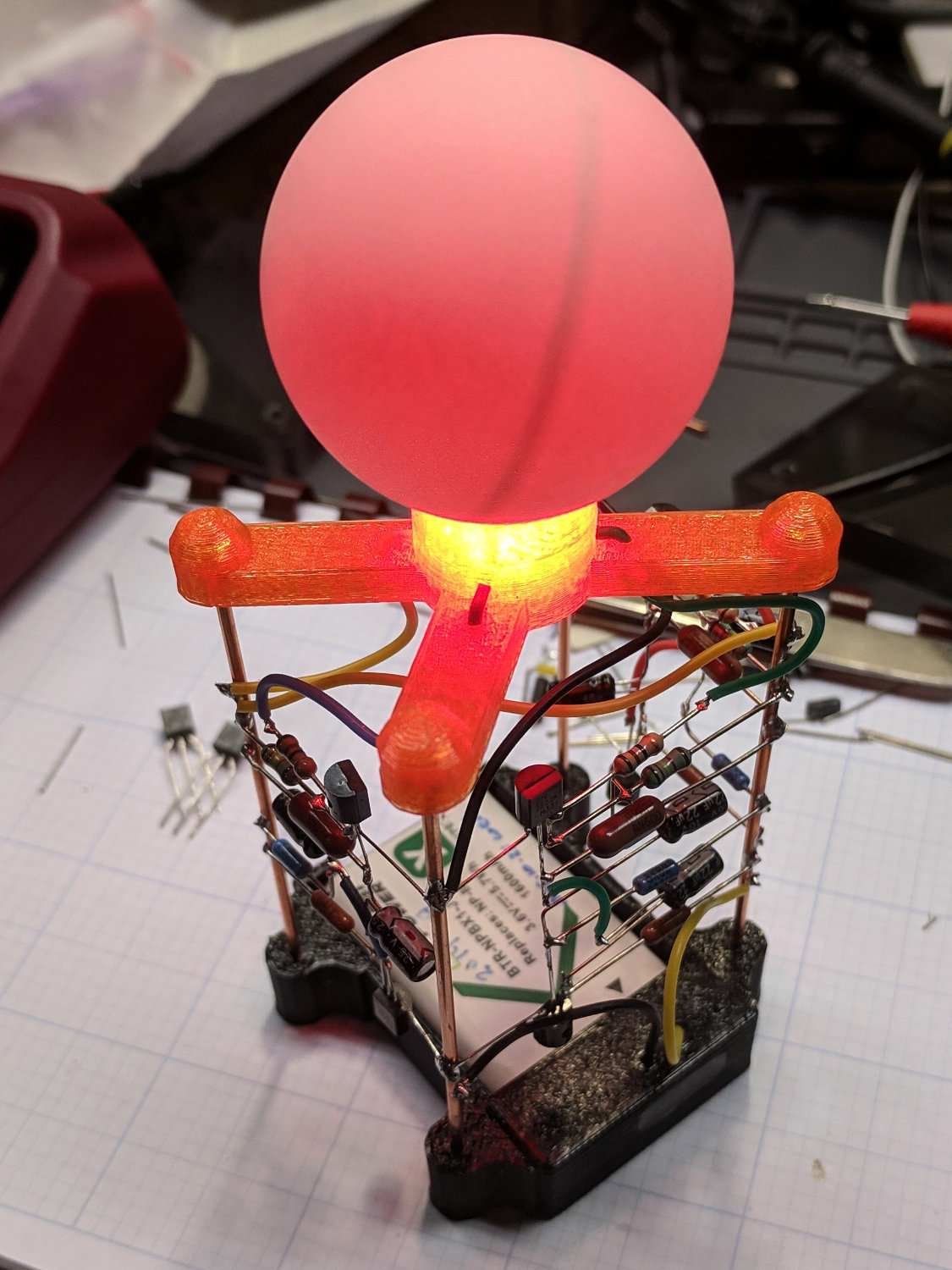
The blue LED works, too, but I didn’t catch any of those blinks.
The spider should be done in black PETG, just like the battery holder, but I didn’t realize which filament was running until too late. Even the blue LED lights up the orange spider just fine!
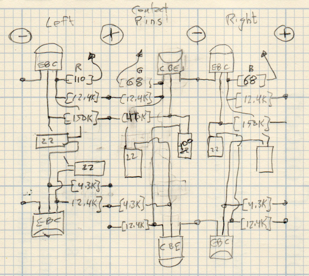
The circuitry behind (well, below) the RGB LED Radome consists of three copies of the original multivibrator, with mirror image layouts to match the wire struts:
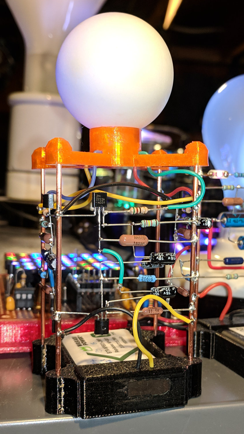
The solder joints adhere to exactly none of the usual good practices:
The simulation matches the actual blink times reasonably well:

It’s unpleasantly frenetic in real life. The next version must have much much longer time constants.
Unfortunately, the simulation also confirms my suspicion that I’ve been abusing the electrolytic capacitors with reverse-polarity waveforms. I suspect it doesn’t really matter too much, as the maximum voltage in either direction remains under a volt at very low currents, but it’s the principle of the thing.
Soooo, lengthening the time constants by increasing the capacitances seems like a Bad Idea.
Alas, increasing the resistors by an order of magnitude won’t work, either, because (despite appearances) the whole thing sits right on the hairy edge of not working. As the battery discharges toward its 2.5 V cutoff level, the currents drop and the circuitry becomes increasingly sensitive to touch. After a day or two, one of the LEDs will jam solidly on, while the others continue to blink merrily away. Removing and reinstalling the battery will sometimes resume proper operation, but it’s definitely not stable enough for production use.
Which makes a MOSFET astable multivibrator seem like a Good Idea.
One could achieve the same visible result with a few cents of microcontroller and a dab of software, but most of the charm comes from its analog nature and all those visible components.

Comments
3 responses to “Astable Multivibrator: RGB LED Circuitry First Light”
Truly a work of art (and technology – they are not mutually exclusive).
Back in the day, a six-transistor circuit would be way out there on the edge!
I had to move all the blinkies out of the living room: it’s amazing how much light comes from half a dozen LEDs in the middle of the night.
[…] an astable multivibrator from MOSFETs for longer time constants and more reliable operation suggests I should know a bit more about their operation with minuscule […]