|
// Machining fixtures for Tek Circuit Computer cursor |
|
// Ed Nisley KE4ZNU Jan 2021 |
|
|
|
Layout = "Show"; // [Show, Build, Cursor, Clamp, Rough, Engrave] |
|
|
|
/* [Hidden] */ |
|
|
|
ThreadThick = 0.25; |
|
ThreadWidth = 0.40; |
|
|
|
HoleWindage = 0.2; |
|
|
|
Protrusion = 0.1; // make holes end cleanly |
|
|
|
inch = 25.4; |
|
|
|
function IntegerMultiple(Size,Unit) = Unit * ceil(Size / Unit); |
|
|
|
module PolyCyl(Dia,Height,ForceSides=0) { // based on nophead's polyholes |
|
Sides = (ForceSides != 0) ? ForceSides : (ceil(Dia) + 2); |
|
FixDia = Dia / cos(180/Sides); |
|
cylinder(d=(FixDia + HoleWindage),h=Height,$fn=Sides); |
|
} |
|
|
|
//———————- |
|
// Dimensions |
|
|
|
CursorHubOD = 1.0*inch; // original Tek CC was hard inch! |
|
CursorTipWidth = (9.0/16.0)*inch; |
|
CursorTipRadius = (1.0/16.0)*inch; |
|
|
|
CursorThick = 0.5; // plastic sheet thickness |
|
|
|
CutterOD = 3.175; // milling cutter dia |
|
CutterDepth = 2.0; // … depth of cut |
|
CutterLip = 0.5; // … clearance under edge |
|
|
|
ScribeOD = 3.0; // diamond scribe shank |
|
|
|
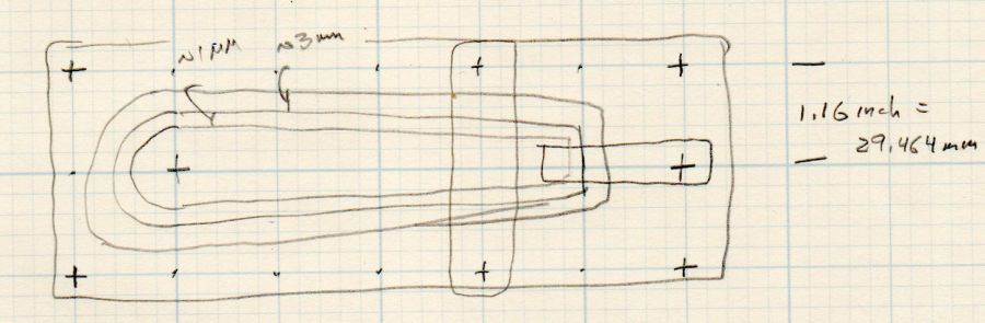
StudOC = [1.16*inch,1.16*inch]; // Sherline tooling plate grid |
|
StudClear = 5.0; // … screw clearance |
|
StudWasher = 11.0; // … washer OD |
|
|
|
CursorOffset = [-2*StudOC.x,0,0]; // hub center relative to fixture center |
|
|
|
// must have even multiples of stud spacing to put studs along centerlines |
|
BasePlateStuds = [6*StudOC.x,2*StudOC.y]; // fixture screws |
|
echo(str("Stud spacing: ",StudOC)); |
|
|
|
CornerRad = 10.0; // corner radius |
|
|
|
BasePlate = [2*StudWasher + BasePlateStuds.x,2*StudWasher + BasePlateStuds.y,5.0]; |
|
echo(str("Base Plate: ",BasePlate)); |
|
|
|
EngravePlate = [5*StudOC.x,1.5*StudOC.y,BasePlate.z]; |
|
echo(str("Engrave Plate: ",EngravePlate)); |
|
|
|
TemplateThick = 6*ThreadThick; |
|
LegendThick = 2*ThreadThick; |
|
|
|
Gap = 3.0; |
|
|
|
//———————- |
|
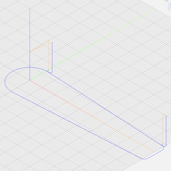
// Import SVG of cursor outline |
|
// Requires our hub OD to match reality |
|
// Hub center at origin |
|
|
|
module CursorSVG(t=CursorThick,od=0) { |
|
|
|
hr = CursorHubOD/2; |
|
|
|
translate([-hr,-hr,0]) |
|
linear_extrude(height=t,convexity=3) |
|
offset(r=od/2) |
|
import(file="/mnt/bulkdata/Project Files/Tektronix Circuit Computer/Firmware/TekCC-Cursor-Mark.svg",center=false); |
|
|
|
} |
|
|
|
//———————- |
|
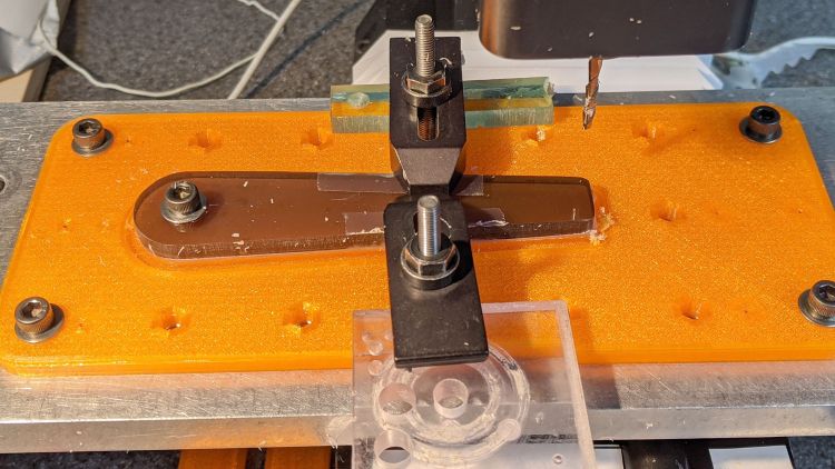
// Milling fixture for cursor blanks |
|
|
|
module Fixture() { |
|
|
|
difference() { |
|
hull() // basic plate shape |
|
for (i=[-1,1], j=[-1,1]) |
|
translate([i*(BasePlate.x/2 – CornerRad),j*(BasePlate.y/2 – CornerRad),0]) |
|
cylinder(r=CornerRad,h=BasePlate.z,$fn=24); |
|
|
|
translate(CursorOffset + [0,0,BasePlate.z – CutterDepth]) |
|
difference() { |
|
CursorSVG(CutterDepth + Protrusion,1.5*CutterOD); |
|
CursorSVG(CutterDepth + Protrusion,-CutterLip); |
|
} |
|
|
|
translate(CursorOffset + [0,0,BasePlate.z – 2*ThreadThick]) { // alignment pips |
|
for (x=[-20.0,130.0], y=[-30.0,0.0,30.0]) |
|
translate([x,y,0]) |
|
cylinder(d=4*ThreadWidth,h=1,$fn=6); |
|
|
|
for (x=[-30.0,130.0,150.0]) |
|
translate([x,0,0]) |
|
cylinder(d=4*ThreadWidth,h=1,$fn=6); |
|
} |
|
|
|
for (i=[-1,1], j=[-1,1]) // mounting stud holes |
|
translate([i*BasePlateStuds.x/2,j*BasePlateStuds.y/2,-Protrusion]) |
|
rotate(180/6) |
|
PolyCyl(StudClear,BasePlate.z + 2*Protrusion,6); |
|
|
|
translate(CursorOffset + [0,0,-Protrusion]) // hub clamp hole |
|
rotate(180/6) |
|
PolyCyl(StudClear,BasePlate.z + 2*Protrusion,6); |
|
|
|
translate([2*StudOC.x,0,-Protrusion]) // tip clamp hole |
|
rotate(180/6) |
|
PolyCyl(StudClear,BasePlate.z + 2*Protrusion,6); |
|
|
|
for (i=[-2:2], j=[-1,1]) // side clamp holes |
|
translate([i*StudOC.x,j*StudOC.y,-Protrusion]) |
|
rotate(180/6) |
|
PolyCyl(StudClear,BasePlate.z + 2*Protrusion,6); |
|
|
|
} |
|
|
|
} |
|
|
|
//———————- |
|
// Show-n-Tell cursor |
|
|
|
module Cursor() { |
|
|
|
difference() { |
|
CursorSVG(CursorThick,0.0); |
|
translate([0,0,-Protrusion]) |
|
rotate(180/6) |
|
PolyCyl(StudClear,TemplateThick + 2*Protrusion,6); |
|
} |
|
} |
|
|
|
|
|
//———————- |
|
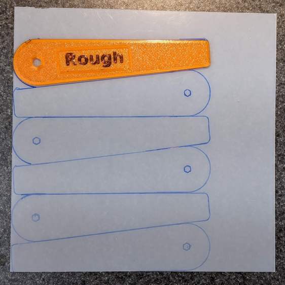
// Template for rough-cutting blanks |
|
|
|
module Rough() { |
|
|
|
bb = [40,12,LegendThick]; |
|
|
|
difference() { |
|
CursorSVG(TemplateThick,1.0); |
|
translate([0,0,-Protrusion]) |
|
rotate(180/6) |
|
PolyCyl(StudClear,TemplateThick + 2*Protrusion,6); |
|
|
|
difference() { |
|
translate([bb.x/2 + CursorHubOD/2,0,TemplateThick – bb.z/2 + Protrusion]) |
|
cube(bb + [0,0,Protrusion],center=true); |
|
translate([bb.x/2 + CursorHubOD/2,0,TemplateThick – bb.z]) |
|
linear_extrude(height=bb.z,convexity=10) |
|
text(text="Rough",size=7,spacing=1.00,font="DejaVu Sans:style:Bold",halign="center",valign="center"); |
|
} |
|
} |
|
} |
|
|
|
//———————- |
|
// Template for aluminium clamping plate |
|
|
|
module Clamp() { |
|
|
|
bb = [40,12,LegendThick]; |
|
|
|
difference() { |
|
CursorSVG(TemplateThick,-1.0); |
|
translate([0,0,-Protrusion]) |
|
rotate(180/6) |
|
PolyCyl(StudClear,TemplateThick + 2*Protrusion,6); |
|
|
|
difference() { |
|
translate([bb.x/2 + CursorHubOD/2,0,TemplateThick – bb.z/2 + Protrusion]) |
|
cube(bb + [0,0,Protrusion],center=true); |
|
translate([bb.x/2 + CursorHubOD/2,0,TemplateThick – bb.z]) |
|
linear_extrude(height=bb.z,convexity=10) |
|
text(text="Clamp",size=7,spacing=1.00,font="DejaVu Sans:style:Bold",halign="center",valign="center"); |
|
} |
|
} |
|
} |
|
|
|
//———————- |
|
// Engraving clamp |
|
|
|
module Engrave() { |
|
|
|
difference() { |
|
|
|
hull() // clamp outline |
|
for (i=[-1,1], j=[-1,1]) |
|
translate([i*(EngravePlate.x/2 – CornerRad),j*(EngravePlate.y/2 – CornerRad),0]) |
|
cylinder(r=CornerRad,h=EngravePlate.z,$fn=24); |
|
|
|
translate(CursorOffset + [0,0,-Protrusion]) |
|
CursorSVG(CursorThick + Protrusion,0.5); // pocket for blank cursor |
|
|
|
translate(CursorOffset + [0,0,-Protrusion]) |
|
rotate(180/6) |
|
PolyCyl(StudClear,EngravePlate.z + 2*Protrusion,6); |
|
|
|
translate([2*StudOC.x,0,-Protrusion]) |
|
rotate(180/6) |
|
PolyCyl(StudClear,EngravePlate.z + 2*Protrusion,6); |
|
|
|
hull() { |
|
for (i=[-1,1]) |
|
translate([i*1.5*StudOC.x,0,-Protrusion]) |
|
PolyCyl(2*ScribeOD,EngravePlate.z + 2*Protrusion,8); |
|
} |
|
} |
|
|
|
} |
|
|
|
|
|
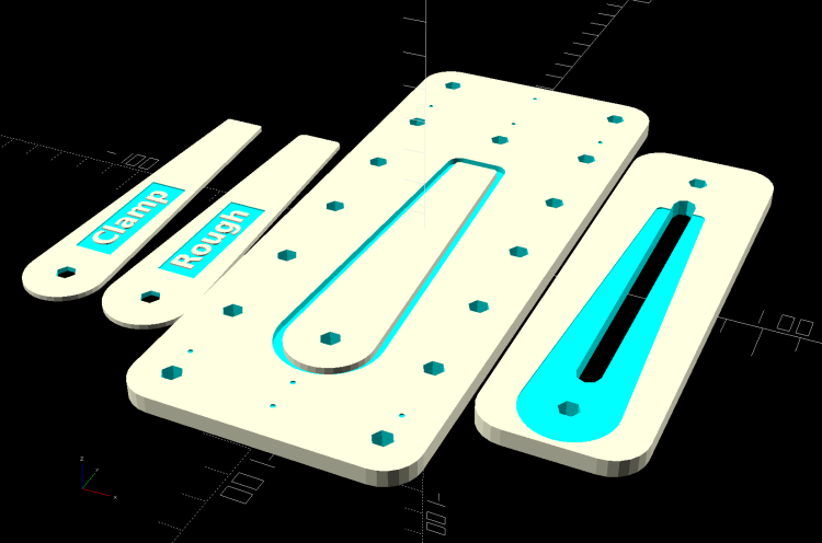
//———————- |
|
// Build it |
|
|
|
if (Layout == "Cursor") { |
|
Cursor(); |
|
} |
|
|
|
if (Layout == "Clamp") { |
|
Clamp(); |
|
} |
|
|
|
if (Layout == "Rough") { |
|
Rough(); |
|
} |
|
|
|
if (Layout == "Engrave") { |
|
Engrave(); |
|
} |
|
|
|
if (Layout == "Show") { |
|
Fixture(); |
|
color("Green",0.3) |
|
translate(CursorOffset + [0,0,BasePlate.z + Protrusion]) |
|
Cursor(); |
|
|
|
color("Orange") |
|
translate(CursorOffset + [0,0,BasePlate.z + 10]) |
|
Rough(); |
|
|
|
|
|
color("Brown") |
|
translate(CursorOffset + [0,0,BasePlate.z + 20]) |
|
Clamp(); |
|
|
|
color("Gold") |
|
translate(0*CursorOffset + [0,0,BasePlate.z + 40]) |
|
Engrave(); |
|
|
|
} |
|
|
|
if (Layout == "Build"){ |
|
rotate(90) { |
|
Fixture(); |
|
translate([0,-((BasePlate.y + EngravePlate.y)/2 + Gap),EngravePlate.z]) |
|
rotate([180,0,0]) |
|
Engrave(); |
|
translate(CursorOffset + [0,(BasePlate.y + CursorHubOD)/2 + Gap,0]) |
|
Rough(); |
|
translate(CursorOffset + [0,(BasePlate.y + 3*CursorHubOD)/2 + 2*Gap,0]) |
|
Clamp(); |
|
} |
|
} |
|
|