Ed Nisley's Blog: Shop notes, electronics, firmware, machinery, 3D printing, laser cuttery, and curiosities. Contents: 100% human thinking, 0% AI slop.
Because I live in the future and had solved this problem in the past, eight hours of print time produced a second shade:
Torchiere Lamp Shade 2 – on platform
I sliced the same STL file with PrusaSlicer to get G-Code incorporating whatever configuration changes I’ve made to the M2 over the years and include any slicing algorithm improvements; the OpenSCAD code remains unchanged.
The as-printed shade had pretty much the same crystalline aspect as the first one:
Torchiere Lamp Shade 2 – no epoxy
Smoothing a layer of white-tinted epoxy over the interior while spinning it slowly in the mini-lathe calmed it down enough for our simple needs, although the picture I tried to take didn’t show much difference.
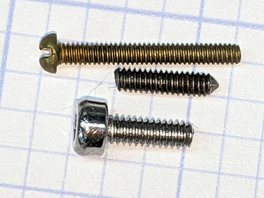
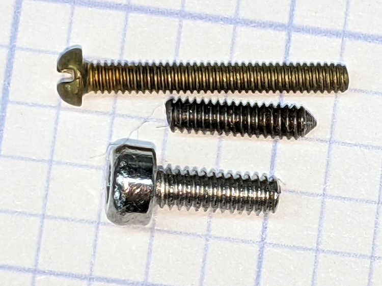
The 1-72 brass screw came heartbreakingly close to fitting and the M2 SHCS obviously won’t play. I can’t measure super-fine threads, but I can count: 16 threads on the stub occupy about the same distance as 18 threads on the 1-72 screw, so 72 × 8 / 9 = 64 tpi and it’s a 1-64 screw, not the far more standard 1-72.
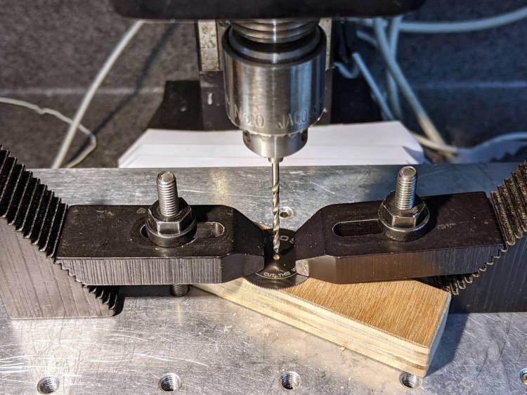
The blade hole just barely fit a #51 = 67 mil drill and measuring my assortment of mandrels produced one with the only M1.8×0.35 (OD = 71 mil) screw I’ve ever seen, so I drilled the blade with a #50 = 70 mil drill:
Gyros miniature saw blade – hole enlarging
Should the oddball screw in that mandrel break, the next step will be a #48 = 76 mil drill to fit the blade around the M2×0.4 screw for cheap and readily available mandrels.
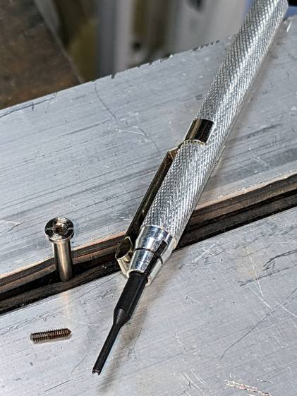
So, being left with a broken screw stub in the original Gyros mandrel, I soaked the scene in Kroil overnight, then applied a tiny screw extractor with amazingly good results:
Gyros mandrel – broken screw extraction
I did eventually find one 1-64 screw in the Big Box o’ Tiny Screws, although its infinitesimal head seems intended for gentler duty than clamping a saw blade to the end of a whirling shaft.
Hand-held Dremel mandrels have, as far as I can tell, no particular runout specs, so chucking them in a Sherline spindle collet pretty much guarantees only a few teeth on one side of the saw will do all the cutting. Which, I hope, will suffice for my simple needs.
While pondering a project requiring a slitting saw, I discovered the clamp on the dial test indicator magnetic mount I’d picked up a while ago didn’t quite fit the 5/32 inch = 4 mm stem on the indicator. The clamp ring is obviously punched from sheet, then formed into its final shape, as the holes are somewhat un-round. Running the proper drill through the holes removed a minute sliver of steel:
Dial test indicator mount – redrilling
And then it fit just fine:
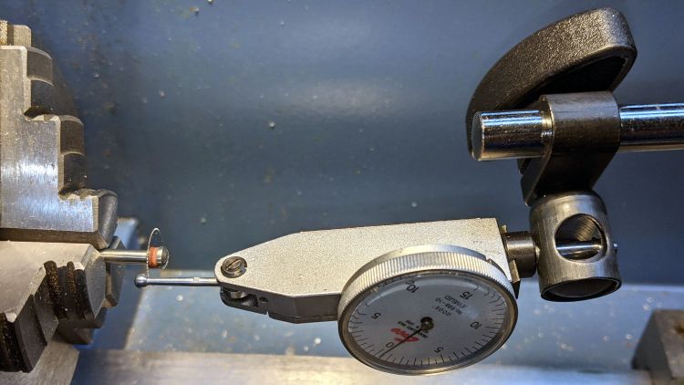
Dial test indicator mount – in use
Although it looks like I’m in the process of sawing the ball off the indicator, I’m really measuring the runout, which turned out to be maybe 5 mils = 0.13 mm. The blade is likely too small for what I’m thinking of using it for, so the pondering continues.
The two bigger holes in the clamp fit the equally standard 3/8 inch = 9.5 mm stems just fine, so it’s just another one of those tools where I get to finish the last few percent of their manufacturing.
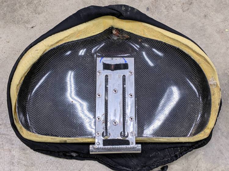
Removing the seat from Mary’s Tour Easy revealed an unexpected sight:
Tour Easy seat – bottom view
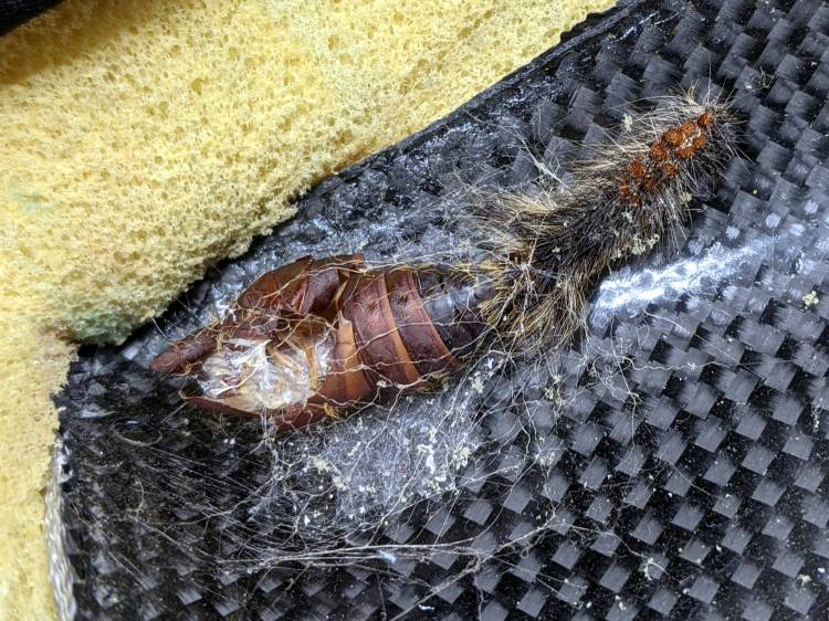
A closer view:
Tour Easy seat – pupal remains
An insect, most likely a rather large butterfly or moth, decided to pupate on the underside of the seat, tucked inside the old seat cover. We can’t fault the critter’s logic!
Mary is sewing up new seat covers for our Tour Easy ‘bents in preparation for the new riding season. Who knows what we’ll find under there in a few years?
You’re supposed to secure the photo backdrop’s top crossbar to the uprights by fiddling with a wingnut, which you must do while reaching over your head. Emart apparently realized this operation was fraught with peril, because the package contains four wingnuts. After setting it up once, I replaced the wingnuts with finger-friendly knobs containing acorn nuts:
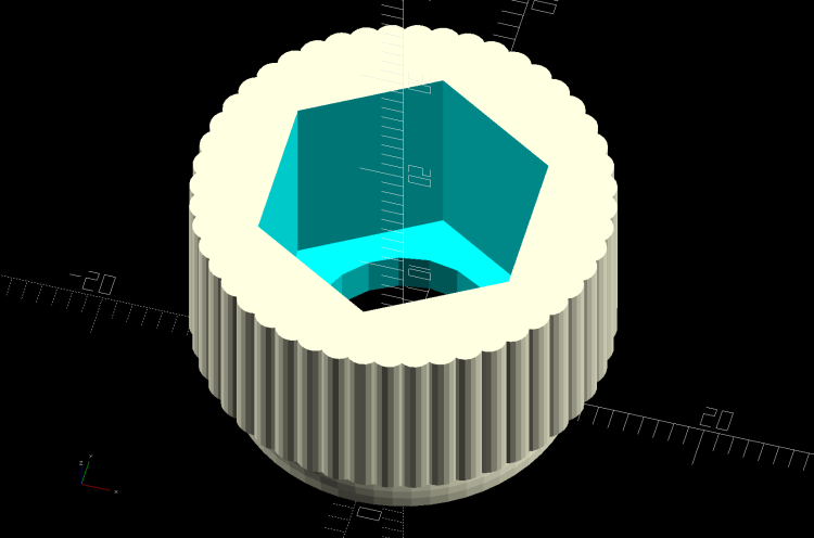
The knobs come from Thingiverse, although the OpenSCAD program required a bit of rework to make it compatible with the current version. Fiddling around with the Customizer parameters produced a Good Enough knob:
M10x1.5 Acorn Nut knob – solid model
I pulled the acorn nut into the knob using the upright pole hardware to keep it aligned. Spin the wingnut on the stud “backwards”, add the washer, push the nut slightly into the knob to get it started, then thread it onto the stud:
Photo Backdrop – knob nut seating – 1
Turn the knob to pull the nut inward until the stud hits the inside of the nut:
Photo Backdrop – knob nut seating – 2
Unthread the nut a bit, run the wingnut out to meet the bottom of the knob, and repeat the operation until the nut bottoms out inside the knob:
Photo Backdrop – knob nut seated
Toss the wingnuts into the Warehouse Wing against later use.
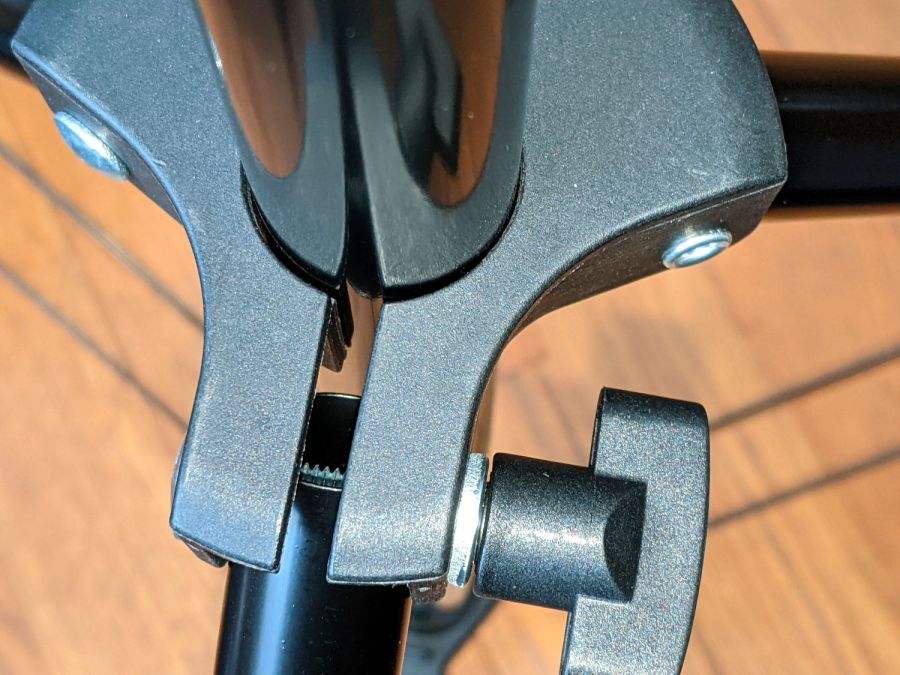
Bonus project: on the other end of the upright, you’ll find it impossible to actually lock the leg carrier against the pole:
Photo Backdrop – tripod leg lock
The plastic fitting is … generously … sized around the 25 mm OD upright pole and requires more compression than I could produce with my puny fingers. It turns out the 18 mm OD leg tube exactly fills the space available inside the fitting, so you (well, I) must squash the steel tube in order to close the fitting on the pole.
Remove the wingnut + screw to free the end of the leg, stick an inch of the leg into the bench vise’s soft jaws, and mash gently to about 16 mm across the holes; it’ll expand slightly in the other direction. Reassemble in reverse order and discover the thumbscrew now squeezes the fitting exactly as it should.
There might be more finishing to do when we actually hang a quilt from the stand, but at least it’s now usable.
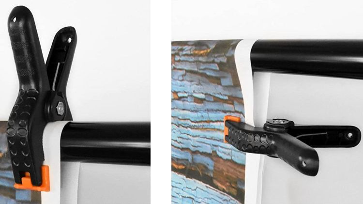
We got a photo backdrop stand to hold Mary’s show-n-tell quilts during her quilting club meetings, but the clamps intended to hold the backdrop from the top bar don’t work quite the way one might expect. These photos snagged from the listing shows their intended use:
Emart Photo Backdrop – clamp examples
The clamp closes on the top bar with the jaws about 15 mm apart, so you must wrap the backdrop around the bar, thereby concealing the top few inches of whatever you intended to show. This doesn’t matter for a preprinted generic backdrop or a green screen, but quilt borders have interesting detail.
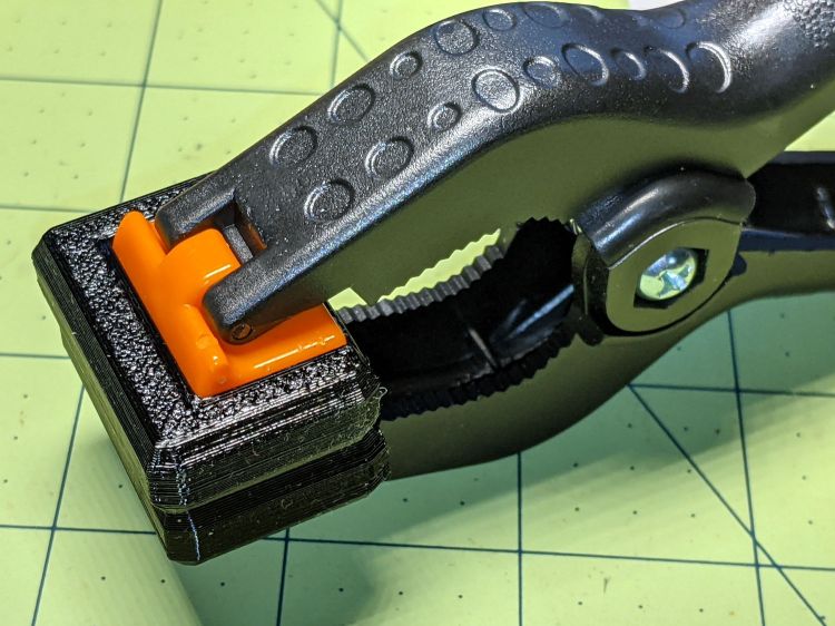
The clamps need thicker jaws, which I promptly conjured from the vasty digital deep:
Spring Clamp Pads – PS preview
The original jaws fit neatly into those recesses, atop a snippet of carpet tape to prevent them from wandering off:
Spring Clamp pads – detail
They’re thick enough to meet in the middle and make the clamp’s serrated round-ish opening fit around the bar:
Spring Clamp pads – compared
With a quilt in place, the clamps slide freely along the bar:
Spring Clamp pads – fit test
That’s a recreation based on actual events, mostly because erecting the stand wasn’t going to happen for one photo.
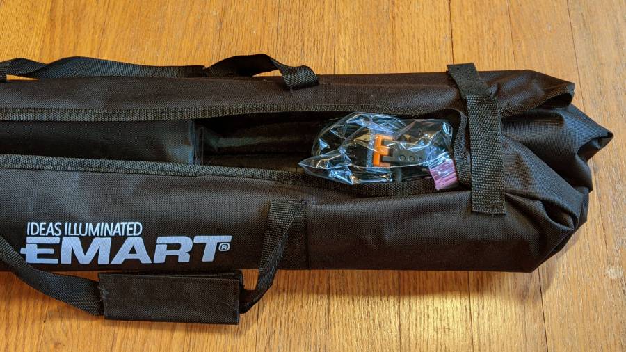
To level set your expectations, the “Convenient Carry Bag” is more of a wrap than a bag, without enough fabric to completely surround its contents:
Emart photo backdrop bag
I put all the clamps / hooks / doodads in a quart Ziploc baggie, which seemed like a better idea than letting them rattle around loose inside the wrap. The flimsy pair (!) of hook-n-loop straps don’t reach across the gap and, even extended with a few inches of double-sided Velcro, lack enough mojo to hold it closed against all the contents.
This file contains hidden or bidirectional Unicode text that may be interpreted or compiled differently than what appears below. To review, open the file in an editor that reveals hidden Unicode characters.
Learn more about bidirectional Unicode characters
After turning the key and dialing the correct combination, the unlocking handle on the basement safe refused to move. Applying the dictum “If brute force isn’t working, you’re not using enough of it”, we eventually persuaded the handle downward and the door swung open. Before applying the dictum “If it doesn’t move and should, use WD-40 [*]”, I had to remove the trim cover from the interior side of the door to gain access to the lockwork.
Start by pressing the two latches inside the small circular holes in the hinge side of the trim cover:
Sentry FireSafe Door – first latches
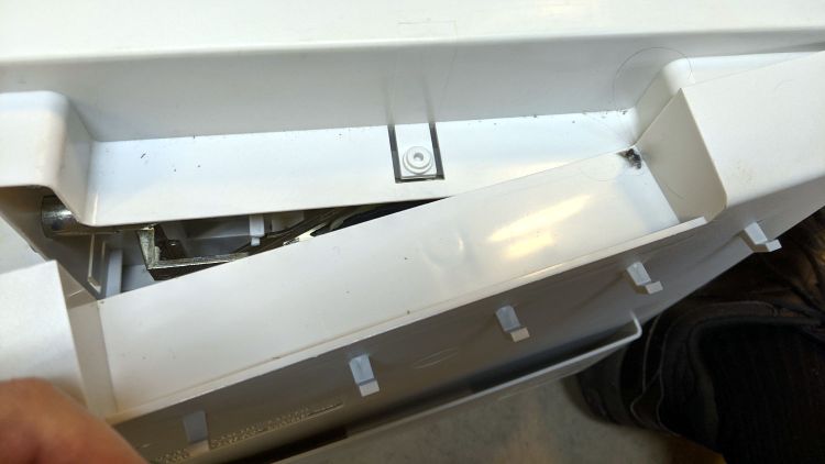
Pull the trim over the slightly chamfered bolts, taking advantage of the fact the bottom pulls out more easily than the top, then pry it upward off the latch in the middle of the top:
Sentry FireSafe Door – top latch
The latches along the other side yield when you bend the trim sufficiently far from the door while applying the Designated Prydriver near the faint mold markings visible around the edge:
Sentry FireSafe Door – last latches
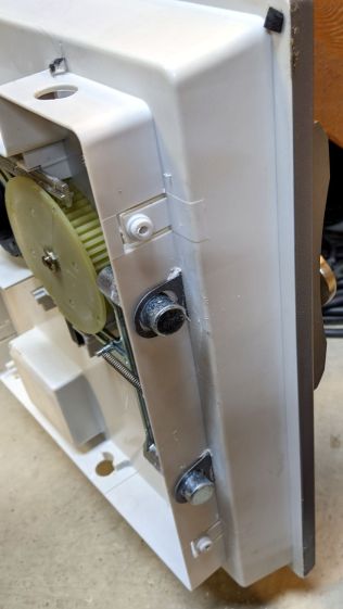
With the trim removed, you can see fancier safes in this line have two additional bolts engaging the top and bottom of the door frame. The rectangular block on the bottom of the hinge side might be for the batteries required by the spendy electronic lock version.
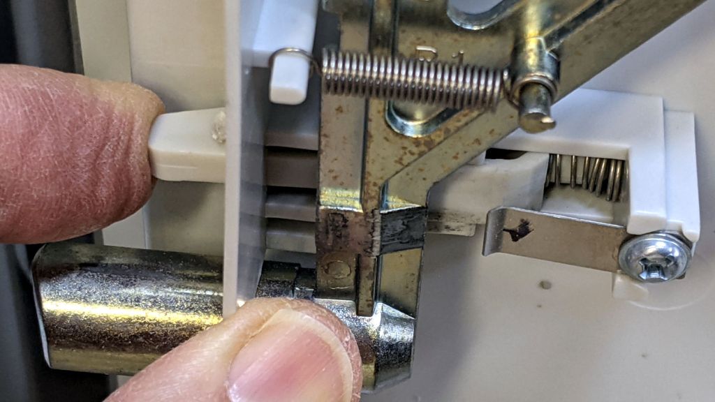
The problem turned out to be a lack of lubrication in the door-closed interlock that prevents you from relocking the bolts and wrecking the mechanism when you try to close the door with the bolts extended:
Sentry FireSafe Door – bolt interlock
A dab of silicone lube on all those sliding interfaces restored the interlock’s good humor.
The bolts had always rubbed just a bit on the trim cover, so I ovalized the offending side of the holes with an Xacto knife.
Slamming the trim firmly back on the door reset the latches, cycling the lockwork resynchronized the interlock, and the safe once again works just like it should.
[*] WD-40 is not the appropriate lube for the lockwork inside a safe, but the dictum aims you in the right direction.