Ed Nisley's Blog: Shop notes, electronics, firmware, machinery, 3D printing, laser cuttery, and curiosities. Contents: 100% human thinking, 0% AI slop.
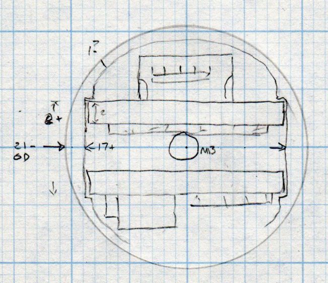
A somewhat more detailed doodle of the end view prompted me to bore the PVC pipe out to 23 mm:
Amber running light – board layout doodle – end
The prospect of designing a 3D printed holder for the boards suggested Quality Shop Time combined with double-stick foam tape would ensure a better outcome.
So I bandsawed the remains of a chunky angle bracket into a pair of rectangles, flycut All The Sides to square them up, and tapped a pair of M3 holes along one edge of each:
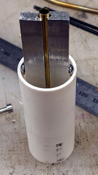
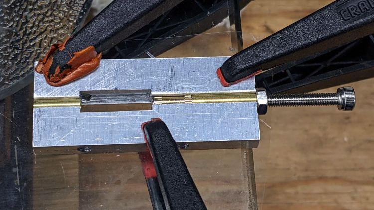
The groove holds a length of 4 mm OD (actually 5/32 inch, but don’t tell anybody) brass tubing:
1 W LED Running Light – baseplate trial fit
The M3 button head screws are an admission of defeat, as I could see no way of controlling the width + thickness of the aluminum slabs to get a firm push fit in the PVC tube. The screws let me tune for best picture after everything else settled out.
A little more machining opened up the top of the groove:
1 W LED Running Light – baseplate dry assembly
A short M3 button head screw (with its head turned down to 4 mm) drops into the slot and holds the slab to the threaded hole in the LED heatsink. The long screw is holding the threaded insert in place for this dry fit.
I doodled a single long screw through the whole thing, but having it fall off the heatsink when taking the rear cover off seemed like a Bad Idea™. An M3 button head screw uses a 2 mm hex key that fits neatly through the threaded insert, thereby making it work.
Butter it up with epoxy, scrape off the excess, and let things cure:
In mostly reverse chronological order, here are various commands I’ve puzzled out:
#xsetwacom --verbose set "HUION Huion Tablet stylus" MapToOutput "DP1-8"
xsetwacom --verbose set "HUION Huion Tablet stylus" MapToOutput "DP-1-8"
#xsetwacom --verbose set "HUION Huion Tablet Pen stylus" MapToOutput "DP-1"
#xsetwacom --verbose set "Wacom Graphire3 6x8 Pen stylus" MapToOutput "DP-1"
#xsetwacom --verbose set "Wacom Graphire3 6x8 Pen stylus" MapToOutput "HEAD-0"
#xsetwacom --verbose set "Wacom Graphire3 6x8 Pen eraser" MapToOutput "DP-1"
#xsetwacom --verbose set "Wacom Graphire3 6x8 Pen eraser" MapToOutput "HEAD-0"
Over the last two years, the display name changed from DP-1 to DP-1-8 to DP1-8, and back to DP-1-8. I grew accustomed to this with the Wacom tablet (HEAD-0‽)and now know where to look, but I still have no idea of the motivation.
Aaaand the tablet’s stylus name? The Wacom names were stable, but the Huion names apparently come from the Department of Redundancy Department.
In this case, a German “visitor” read nearly all of my 4461 posts on two days: 822 + 3561 = 4383. I’m reasonably sure no human finds my writing that interesting, so it’s likely a scraper capturing my text for the purposes of spinning it into a blog-like site with “unique content” for the purposes of SEO.
Perhaps the first traffic spike was a targeting run?
I’ll never know the rest of the story, but if you happen to stumble across a blog with an uncanny resemblance to this one, written by something with a wide vocabulary and no techie knowledge, let me know.
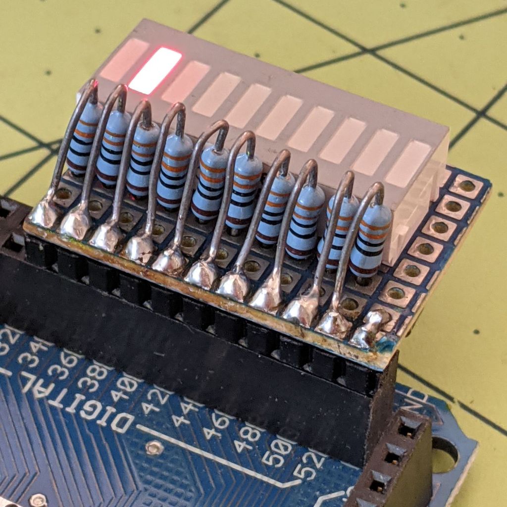
Kibitzing on a project involving an Arduino Mega (properly MEGA, but who cares?) with plenty of spare I/O pins led me to slap together a block of LEDs:
Arduino Mega Debugging LEDs
The excessive lead length on the 330 Ω resistors will eventually anchor scope probes syncing on / timing interesting program events.
Not that you have any, but they’re antique HP HDSP-4836 tuning indicators: RRYYGGYYRR. If you were being fussy, you might use 270 Ω resistors on the yellow LEDs to brighten them up.
A simple test program exercises the LEDs:
/*
  Debugging LED outputs for Mega board
  Ed Nisley - KE4ZNU
  Plug the board into the Digital Header pins 34-52 and GND
*/

byte LowLED = 34;
byte HighLED = 52;
byte ThisLED = LowLED;

//-----
void setup() {
  pinMode(LED_BUILTIN,OUTPUT);

  for (byte p = LowLED; p <= HighLED; p+=2)
    pinMode(p, OUTPUT);

//  Serial.begin(9600);
}

// -----
void loop() {
  digitalWrite(LED_BUILTIN,HIGH);

  digitalWrite(ThisLED, HIGH);
  delay(100);
  digitalWrite(ThisLED, LOW);
 // delay(500);

  ThisLED = (ThisLED < HighLED) ? (ThisLED + 2) : LowLED;

//  Serial.println(ThisLED);

  digitalWrite(LED_BUILTIN,LOW);
}
Nothing fancy, but it ought to come in handy at some point.
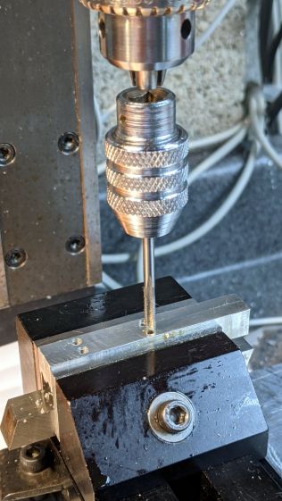
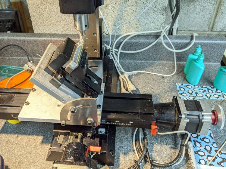
The need to gnaw a V groove into the side of two 60 mm aluminum bars led to this Sherline CNC mill setup:
Sherline Y-Axis Nut Mishap – setup
Milling the near end of the bars put the angle plate’s rear lock screw within a millimeter of the column; the vise fits in exactly one spot on the angle plate and that’s where the jaws must be.
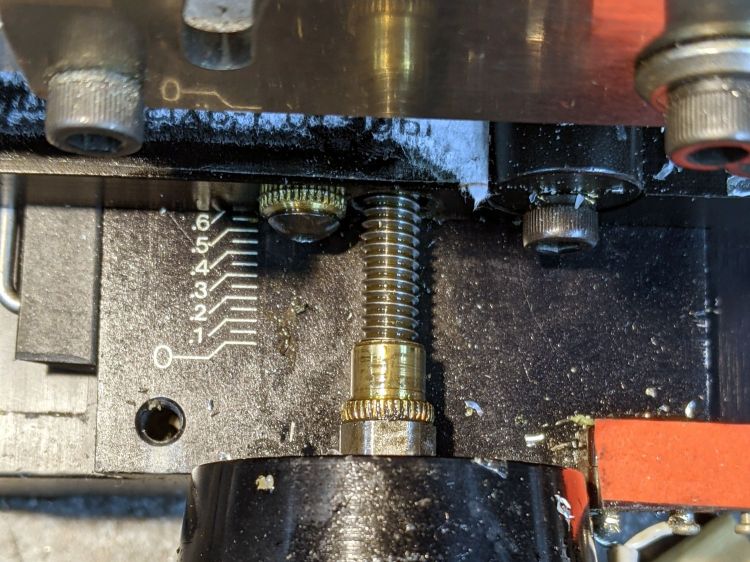
While controlling the mill with the Joggy Thing and some manual command entry, because it’s easier than real CNC programming, I overshot the near end and rammed the column with enough enthusiasm to dislodge the Y-axis leadscrew nut. An interlude of utter confusion ended with the backlash preload nut firmly jammed against the leadscrew coupler on the other end of travel:
Sherline Y-Axis Nut Mishap – stuck preload nut
The paper shreds show where the bellows formerly stuck on the Y axis stage.
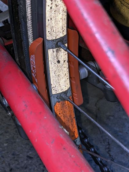
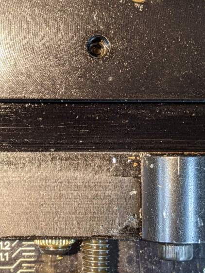
The backlash nut chewed off a few star lock gear teeth on its way out, as seen here just above where they mesh:
Sherline Y-Axis Nut Mishap – chewed star nut
It’s been quite a few years since I took the thing apart to replace the nuts, so I used the opportunity to lube the otherwise inacessible X axis leadscrew inside its table upside down on the bench.
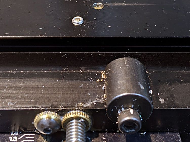
The setscrew locking the Y axis leadscrew nut in place heaves into view with the X axis table off:
Sherline Y-Axis Nut Mishap – setscrew
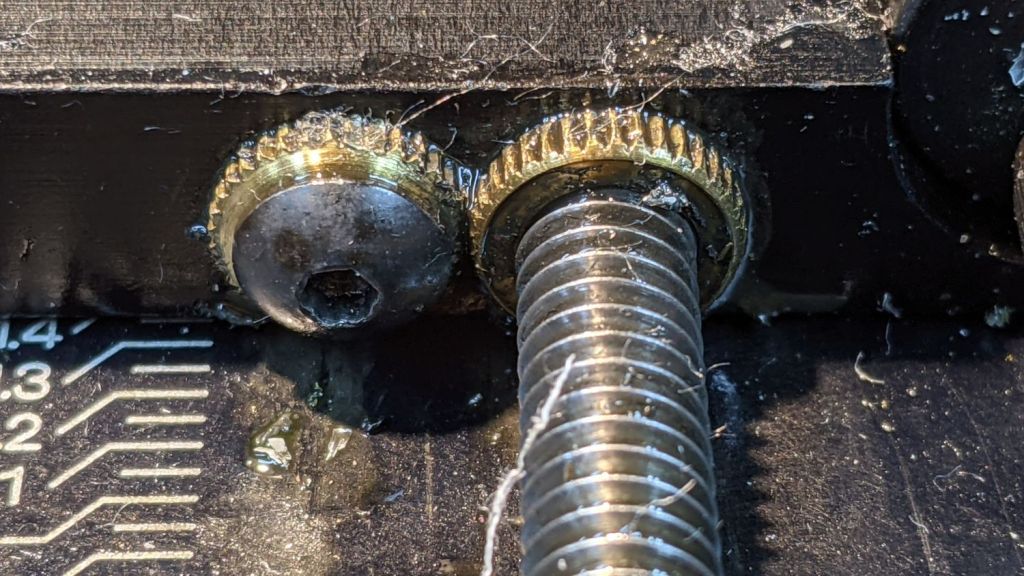
I thought about jamming it in place with a second 10-32 setscrew, but the ones on hand were just an itsy too long and collided with the X-axis table:
Sherline Y-Axis Nut Mishap – doubled setscrew
The thought of having the additional setscrew work loose, grind into the underside of the table, and require major surgery for recovery persuaded me to drop it back in the drawer.
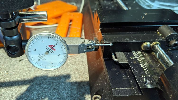
With everything in place, I adjusted the backlash (on both axes) down to a few mils:
Sherline Y-Axis Nut Mishap – backlash test
Tweaking the X axis preload nut under the table is not my idea of a good time, but it’s been quite a while since I had to do that.
Folding the new paper bellows and installing them took about as long as repairing the mill.
Milling the second V groove worked fine; all is right with the Sherline again.