Kibitzing on a project involving an Arduino Mega (properly MEGA, but who cares?) with plenty of spare I/O pins led me to slap together a block of LEDs:
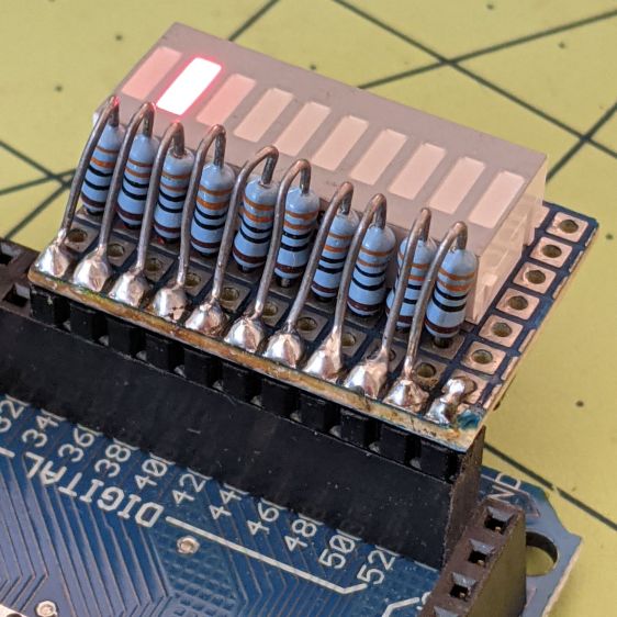
The excessive lead length on the 330 Ω resistors will eventually anchor scope probes syncing on / timing interesting program events.
Not that you have any, but they’re antique HP HDSP-4836 tuning indicators: RRYYGGYYRR. If you were being fussy, you might use 270 Ω resistors on the yellow LEDs to brighten them up.
A simple test program exercises the LEDs:
/*
  Debugging LED outputs for Mega board
  Ed Nisley - KE4ZNU
  Plug the board into the Digital Header pins 34-52 and GND
*/

byte LowLED = 34;
byte HighLED = 52;
byte ThisLED = LowLED;

//-----
void setup() {
  pinMode(LED_BUILTIN,OUTPUT);

  for (byte p = LowLED; p <= HighLED; p+=2)
    pinMode(p, OUTPUT);

//  Serial.begin(9600);
}

// -----
void loop() {
  digitalWrite(LED_BUILTIN,HIGH);

  digitalWrite(ThisLED, HIGH);
  delay(100);
  digitalWrite(ThisLED, LOW);
 // delay(500);

  ThisLED = (ThisLED < HighLED) ? (ThisLED + 2) : LowLED;

//  Serial.println(ThisLED);

  digitalWrite(LED_BUILTIN,LOW);
}
Nothing fancy, but it ought to come in handy at some point.

Comments
4 responses to “Arduino MEGA Debugging LEDs”
Beautiful blinkenlights!
Well played, sir!
I built something similar, to help me debug an ATtiny10 I was trying to program about a year ago – using SMT. It was quite satisfying to see the micro-controller toggling the LEDs as designed.
Anyways, I stumbled upon your blog today and would like to thank you for taking the time to document your projects and ruminations for us to see!
The guy doing the code on that project comes from big IBM systems programming; he was delighted with the prospect of actually twiddling a single I/O bit and seeing the results.
Thanks for the good words; mostly, I’m reminding myself what I did for the next time around …