Ed Nisley's Blog: Shop notes, electronics, firmware, machinery, 3D printing, laser cuttery, and curiosities. Contents: 100% human thinking, 0% AI slop.
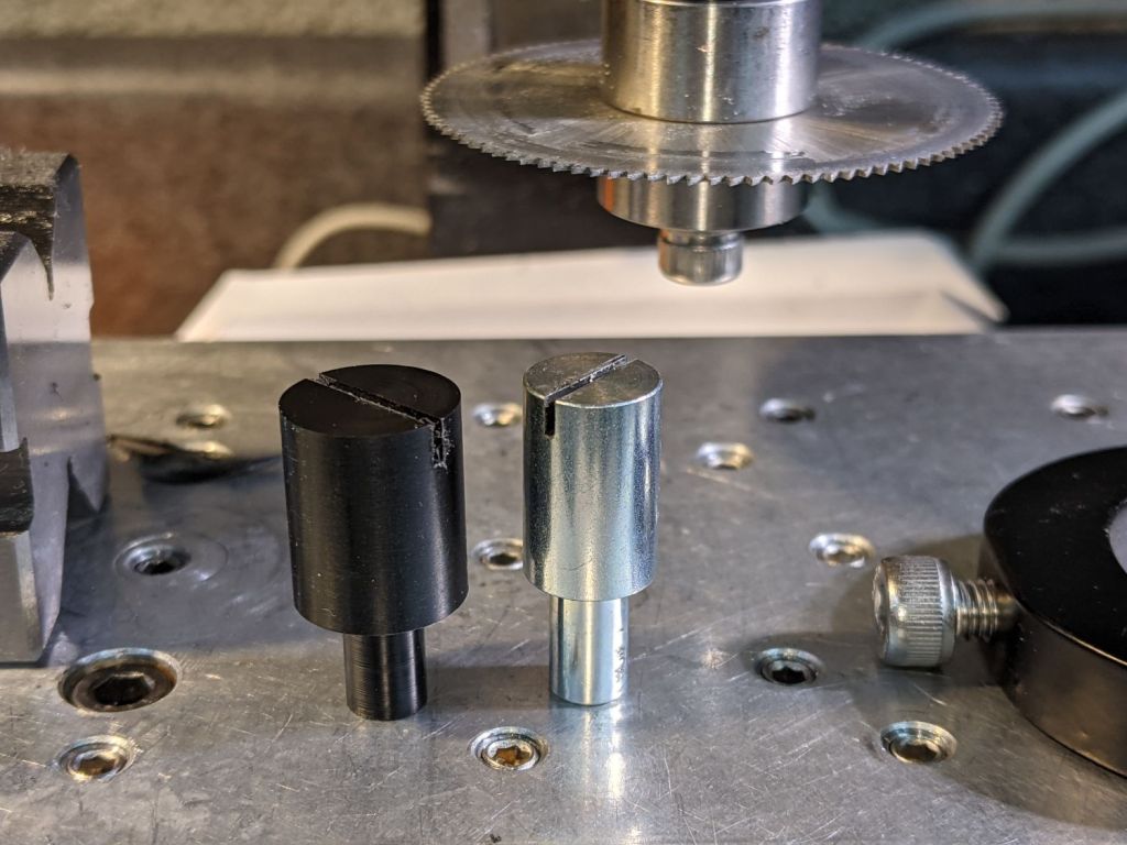
The Micro-Mark bandsaw has a metal blade guide below the table that contributes to the awful noise it makes while running, even when it’s not cutting anything. Having recently touched the Delrin = acetal rod stash, a simple project came to mind.
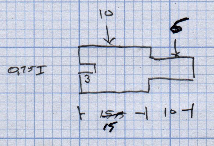
A doodle with the original metal guide dimensions:
Micro-Mark Bandsaw – metal blade guide dimensions
The 10 mm dimension is non-critical, so I started with a 1/2 inch acetal rod and turned the stub end to match.
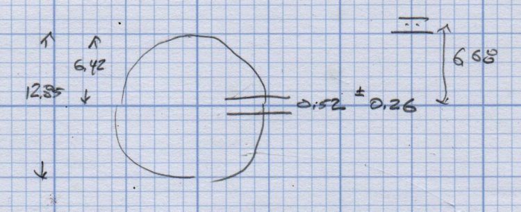
A doodle suggested how to carve the slot with a 20.5 mil = 0.52 mm slitting saw, with the offset from a Z touchoff at the top:
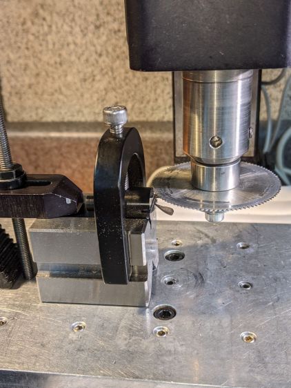
The V block setup required swapping out the overly long OEM screw for a shorter 5 mm SHCS to clear the Sherline’s motor:
Micro-Mark Bandsaw – acetal guide slitting
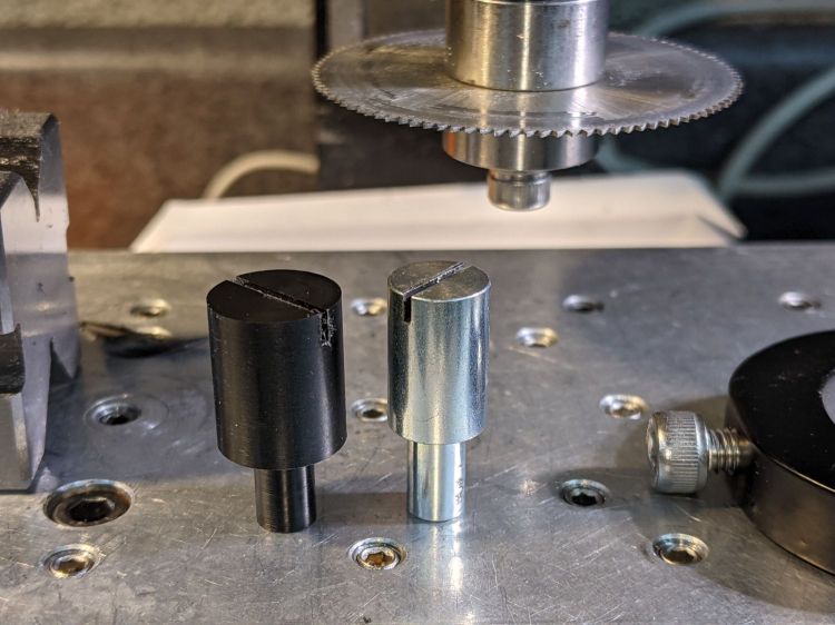
The end result looked pretty good:
Micro-Mark Bandsaw – acetal vs steel blade guides
And it looks like it pretty much belongs in the saw:
Micro-Mark Bandsaw – acetal blade guide installed
The 6 mm stud goes into a hole in the frame, where a setscrew holds it in place. You must remove the blade to extract / replace the guide, with the correct position having the end of the slot just touching the back of the blade.
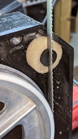
The foam ring apparently keeps crud away from the stud on the backside; I doubt it’s mission-critical.
The saw became somewhat quieter; the ball bearing guides above the table now generate most of the racket. At some point I’ll try replacing them with a block, probably made from UHMW, with a simple slit to guide the blade.
Plastic guides may not last as long as the steel ones, but occasional replacements will be worth it if the saw runs quieter.
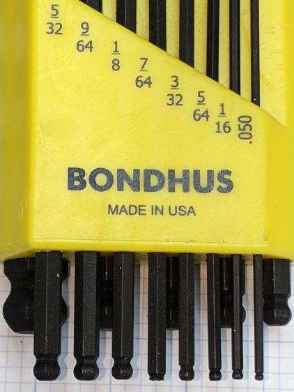
When I applied the 7/64 wrench to a setscrew, the missing ball came as a surprise.
Even though the inch wrench set doesn’t get a lot of use, it’s possible I broke the ball off during a previous adventure, but a look at the end shows the black oxide coating covering the end:
Bondhus hex wrenches – missing 7-64 ball – detail
Yeah, it was born that way.
I wonder if and how their lifetime guarantee works.
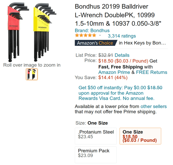
Protip: as of this writing, the Amazon listing has two other “sizes” showing exactly the same set at significantly higher prices from two randomly named sellers:
Bondhus hex wrench set – Amazon listing
It is safe to assume Amazon no longer has its customers’ best interests in mind.
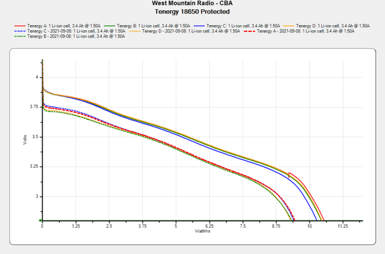
The overall capacity is down by 10%, with the voltage depressed by 120 mV over most of the curve.
Although I don’t keep daily records, the back of the envelope reveals 150 to 200 hour-long rides per year during the last four years, so call it 700 charging cycles:
Anker LC40 Flashlight – Anodizing fade
High brightness draws 1.5 A and low is 50% duty cycle, so a typical ride requires 750 mA·h = 2.5 W·h. Each cell lives for three or four rides with the LED set to low brightness and the numbers work out close enough.
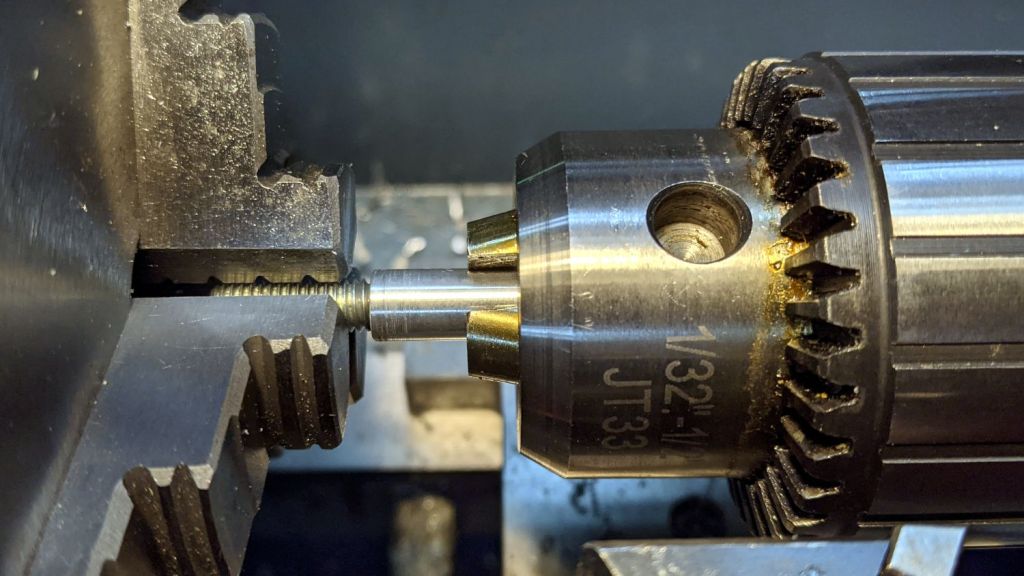
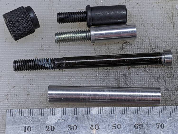
A depth gauge arrived with a 3/8 inch = 9.5 mm mounting rod that fit one of my magnetic bases, but another base in my collection has a 5/16 inch = 7.9 mm clamp. Having recently rummaged through the aluminum rod stash, this happened:
Depth Gauge mounting rods
The original rod at the top has an M6 thread, the drawer of random M6 screws provided suitable volunteers, and a bit of lathe work removed / shaped their heads accordingly.
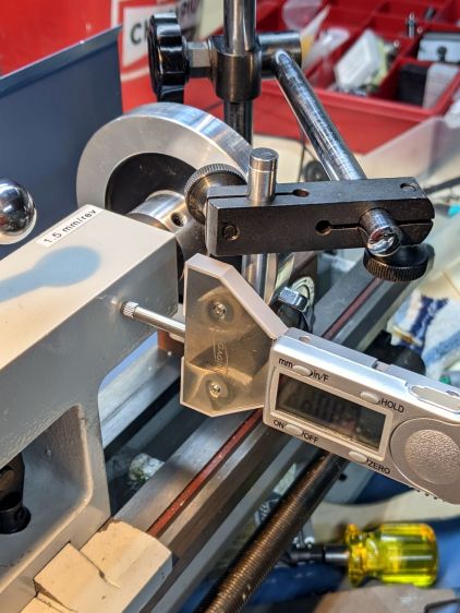
The shorter rod has a blind hole, with a dab of epoxy holding the headless screw in place. Not that it matters, but the lathe held them in alignment for curing:
Depth Gauge mounting rod – epoxy alignment
The longer rod got drilled all the way through, with more epoxy holding the screw, and, even with a relatively loose fit, no worries about alignment.
The longer rod gets the clamp away from the depth gauge’s base plate for better positioning:
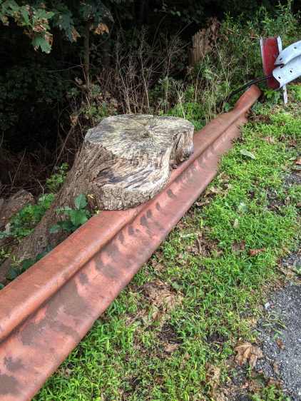
Found behind a store in Red Oaks Mill, overlooking the Mighty Wappingers Creek:
Tree stump around guide rail
The old rail fell off its (long gone) post before the tree grew around it and the newer rail (upper right) definitely isn’t fresh from the factory, so this tableau has been on display for quite a while.
The tree’s growth rings have pretty much weathered away.
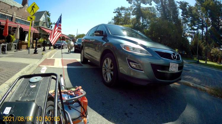
We’re bicycling on Collegeview Avenue, approaching the eastern traffic circle (of three) along Raymond Avenue. I’m in the lead, hauling a trailer with the week’s groceries:
Zero Clearance – Ed Front – 2021-09-07 – 0497
The four digit frame numbers tick along at 60 fps for my helmet camera and 30 fps for the rear cameras.
Note the “splitter” (a.k.a. “pedestrian refuge”) on the left, intended to separate Collegeview’s incoming and outgoing traffic. It formerly had one non-reflective black bollard on each side of the ladder crosswalk, but errant drivers destroyed so many bollards along Raymond that they’re now WONTFIX remnants. The flush concrete disk in the lower left of this picture will become relevant in a few seconds of real time:
Zero Clearance – Ed Front – 2021-09-07 – 0593
Collegeview has the same deteriorating pavement as found along Raymond Avenue, so we must maneuver beside the potholes:
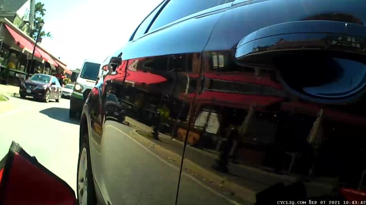
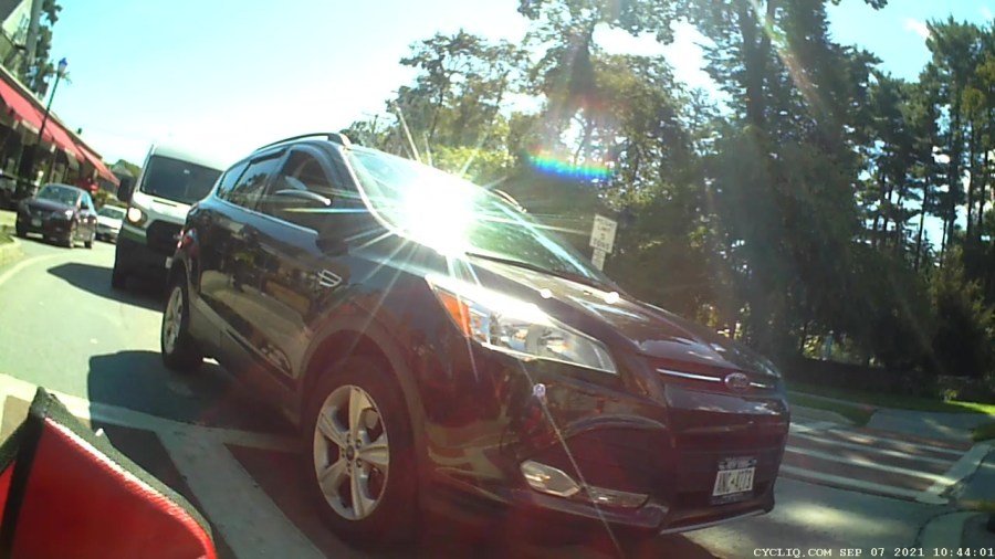
All of us are slowing to stop at the traffic circle, with Mary behind the car that will eventually stop beside me:
Zero Clearance – Ed Rear – 2021-09-07 – 1522
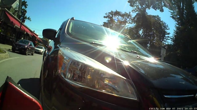
Mary could see the car behind her in her helmet mirror, but she’s slowing to stall speed with no time for sightseeing and no room for maneuvering. The view from the camera on the seat frame behind her left shoulder:
Zero Clearance – Mary – 2021-09-07 – 0957
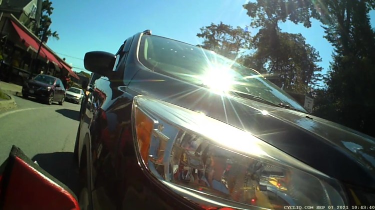
Two seconds later:
Zero Clearance – Mary – 2021-09-07 – 1078
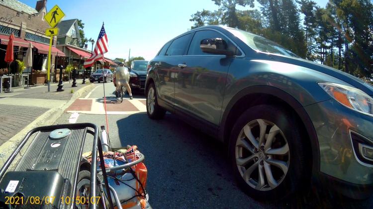
One second:
Zero Clearance – Mary – 2021-09-07 – 1110
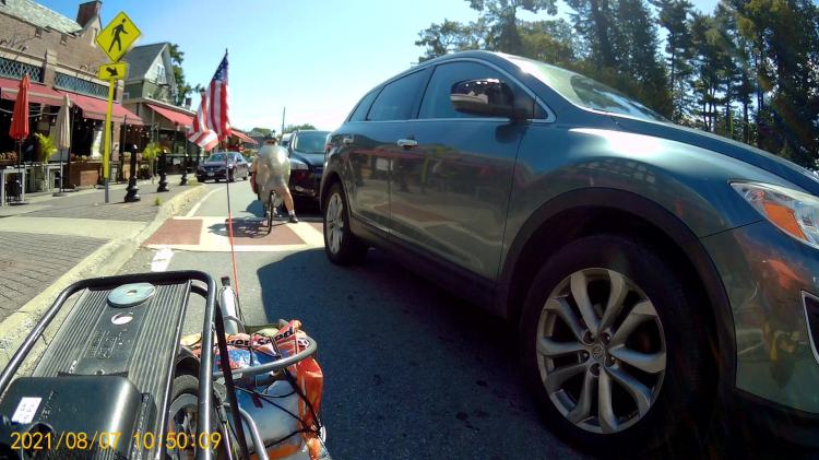
Two more seconds:
Zero Clearance – Mary – 2021-09-07 – 1182
Mary has stopped, as shown by the parked car’s unchanging position in the frame over on the left in the next images. The driver, however, continues creeping slowly forward; there can be no doubt she sees Mary at this distance.
After three more seconds:
Zero Clearance – Mary – 2021-09-07 – 1270
One second later, the front wheel is exactly at Mary’s left foot:
Zero Clearance – Mary – 2021-09-07 – 1308
The same events, viewed from the camera on my bike, start less than one second from the 1522 image above. I’m stopped, while the driver next to me continues to roll forward.
Mary is extending her left leg in preparation for a complete stop, at about the same time as the 1078 image:
Zero Clearance – Ed Rear – 2021-09-07 – 1542
Three seconds later her toe touches the pavement, while both she and the driver continue moving forward very slowly:
Zero Clearance – Ed Rear – 2021-09-07 – 1634
Five seconds later, she is stopped with her foot firmly planted:
Zero Clearance – Ed Rear – 2021-09-07 – 1773
And the driver continues moving:
Zero Clearance – Mary – 2021-09-07 – 1333
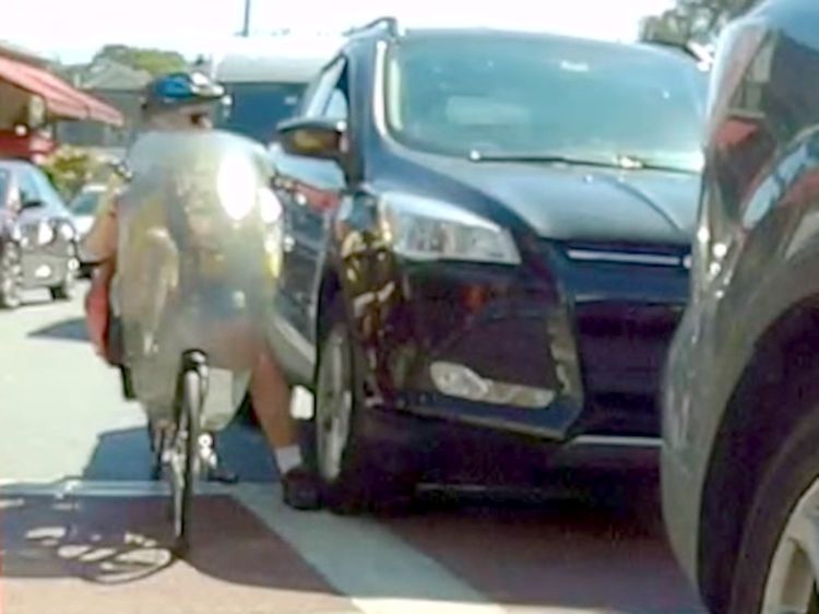
Another five seconds and the sidewall bulge of the car’s radial tire is pressing her foot to the pavement:
Zero Clearance – Ed Rear – 2021-09-07 – 1934
A closer look:
Zero Clearance – Ed Rear – 2021-09-07 – 1946 detail
She yanks her foot away:
Zero Clearance – Ed Rear – 2021-09-07 – 1953
While the driver continues to creep forward:
Zero Clearance – Mary – 2021-09-07 – 1397
Sometimes, it’s the only way to get some attention:
Zero Clearance – Ed Rear – 2021-09-07 – 2026
Mary is now off-balance, leaning on the car door, explaining what just happened:
Zero Clearance – Ed Rear – 2021-09-07 – 2152
Mary regains her balance as the driver backs cautiously away:
Zero Clearance – Mary – 2021-09-07 – 1546
Were the bollard still atop that sad concrete foundation, the driver might not have driven up on the splitter to get around Mary, if only to avoid scuffing a fender:
Zero Clearance – Ed Rear – 2021-09-07 – 2479
Compare this clearance with what you saw earlier in the 0957 image:
Zero Clearance – Mary – 2021-09-07 – 1627
Mary can’t get far enough away, but this must suffice:
Zero Clearance – Ed Rear – 2021-09-07 – 2761
Now the driver can pass her again with more clearance:
Zero Clearance – Mary – 2021-09-07 – 1891
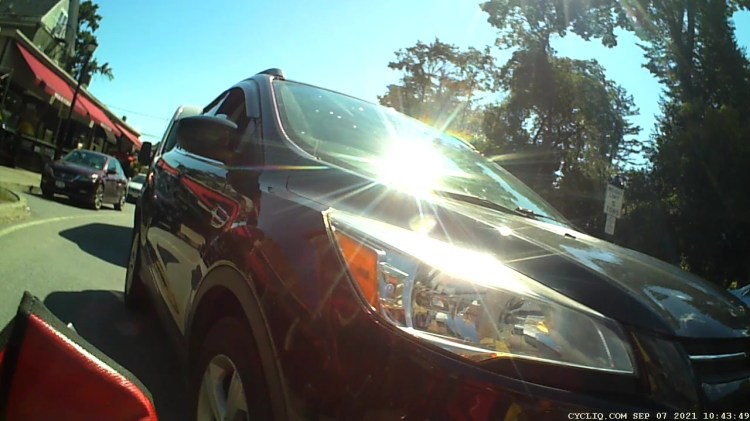
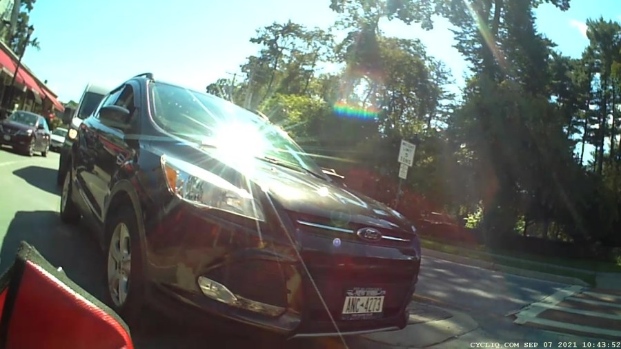
I pointed to the car, then to the circle, and shouted “GO!” because neither of us wanted to be in front of that particular driver:
Zero Clearance – Ed Front – 2021-09-07 – 2540
We’ll surely meet her again, ideally with more clearance.