Ed Nisley's Blog: Shop notes, electronics, firmware, machinery, 3D printing, laser cuttery, and curiosities. Contents: 100% human thinking, 0% AI slop.
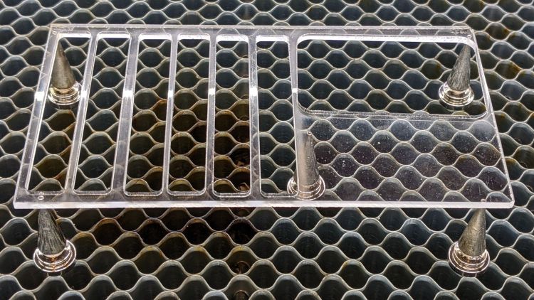
I cut new shades from vintage clear acrylic sheet, with more aluminized mylar attached to the lower surface: you can barely see the COB LED strip through the reflecting surface.
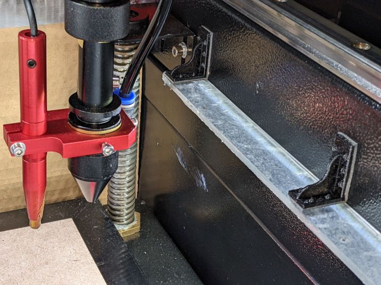
Depending on how you arrange all the hardware hanging on the nozzle, the shades can collide with something at the home position in the far right corner:
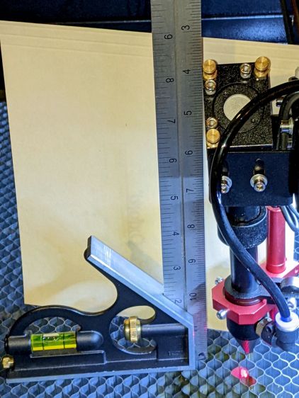
The mirror 3 + lens tube has a distinct tilt when seen from the +X direction (the right side of the machine, so it’s in the YZ plane, I suppose).
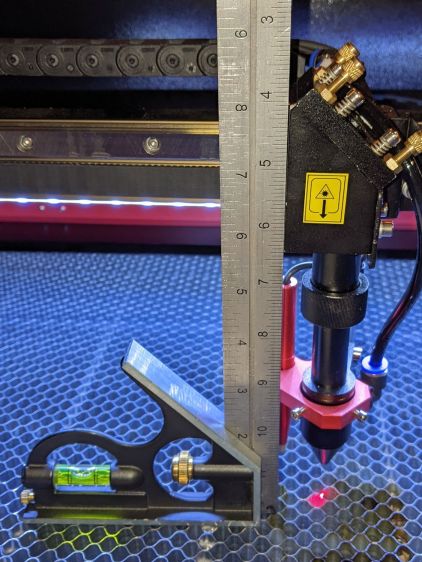
This is not matched when seen from the -Y direction (front):
OMTech 60W beam alignment – head Y plane
The tilt does not seen to correct for a misalignment in the X axis rail or the brackets attaching the head to the linear bearing.
The beam seems properly centered on the lens and nozzle, so I’m loath to twiddle the alignment just to see what happens. One of these days, for sure, that must happen …
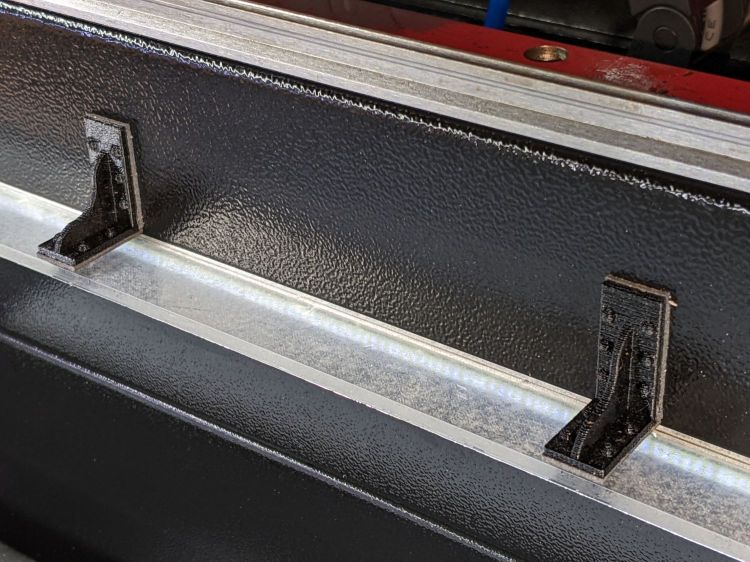
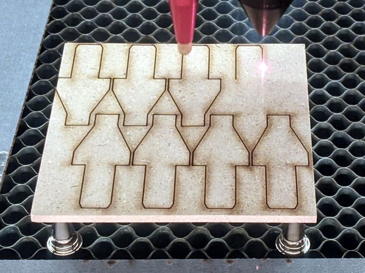
A bit of tinkering suggested I needed a way to repeatably position stock sheets on the honeycomb, so I conjured stops that would be slightly taller than the magnetic spikes:
Improved MDF Honeycomb Spikes – first pass
Three of those form a corner into which you can tuck victims of the same general size:
Improved MDF Honeycomb Spikes – stock alignment
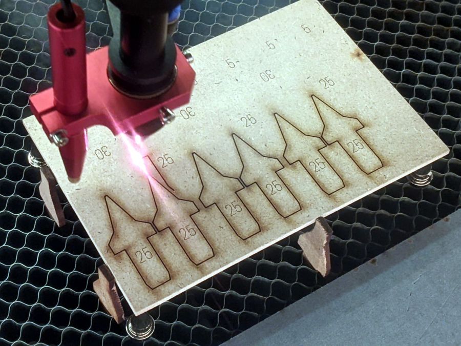
Those pointy MDF spikes should start with slightly rounded tops, because that’s what they’ll look like after a few uses:
Improved MDF Honeycomb Spikes – alignment stops
I also made a low-profile stop for victims lying directly on the honeycomb for engraving:
Please Close The Gate – engraved
The SVG images include a nested version to tile across random MDF leftovers.
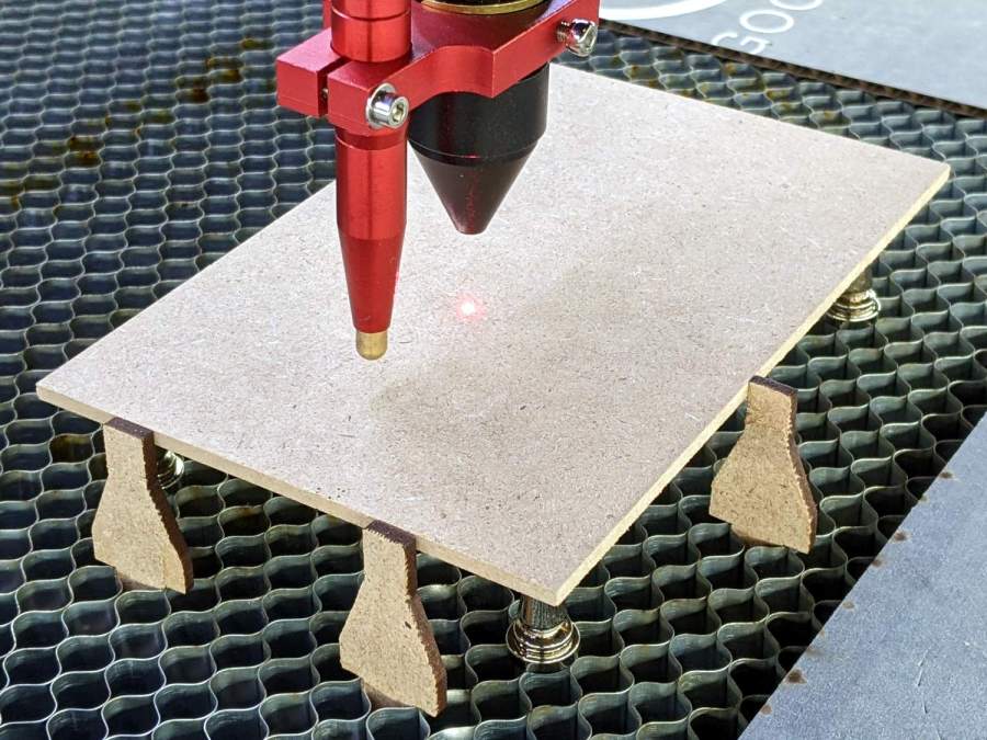
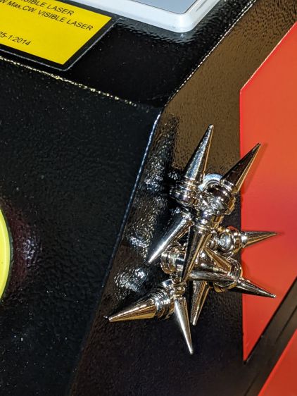
The 12 mm neodymium magnet is slightly larger than a single honeycomb cell, so it wants to center itself atop a cell. The stainless steel button head screw sits in the magnet’s countersunk hole and protrudes just enough to make sure the spike doesn’t slide sideways unless you want it to:
Magnetic Honeycomb Spikes – parts detail
A cloud of combustible gas doesn’t pose a threat under there:
Magnetic Honeycomb Spikes – MDF
The thin red beam comes from the targeting laser on the back of the nozzle.
Storage is easy: just smush a handful of the things against the side of the laser cabinet:
Magnetic Honeycomb Spikes – storage
Buy all the parts in lots of 100 to have supplies for other adventures!
The little DSO-150 oscilloscope has a 1 MΩ || 20 pF input with a 200 kHz bandwidth that should be entirely adequate for the OMTech laser’s millisecond-scale modulation signals from the Gentec ED-200 Optical Joulemeter. There is, however, only one way to be sure:
Gentec ED-200 – scope test setup
The two scope inputs are in parallel, so the joulemeter over on the far right sees a 500 kΩ load, half of the specified 1 MΩ load, with at least twice the capacitance. If the two scopes display pretty much the same result, then it’s good enough.
A 50 ms pulse at half power looks the same on both scopes:
Gentec ED-200 – 50 ms – DSO-150
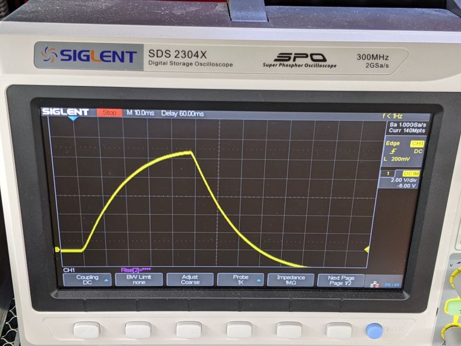
Gentec ED-200 – 50 ms – Siglent
A 50 ms pulse at full power doesn’t quite top out:
Gentec ED-200 – 11V 50ms – DSO-150
Gentec ED-200 – 11V 50ms – Siglent
Given that the pulse duration should be less than the detector’s 1.5 ms risetime, using a 50 ms pulse is absurd. Right now I’m just looking at the overall waveform and detector range, not trying to get useful numbers out of the poor thing.
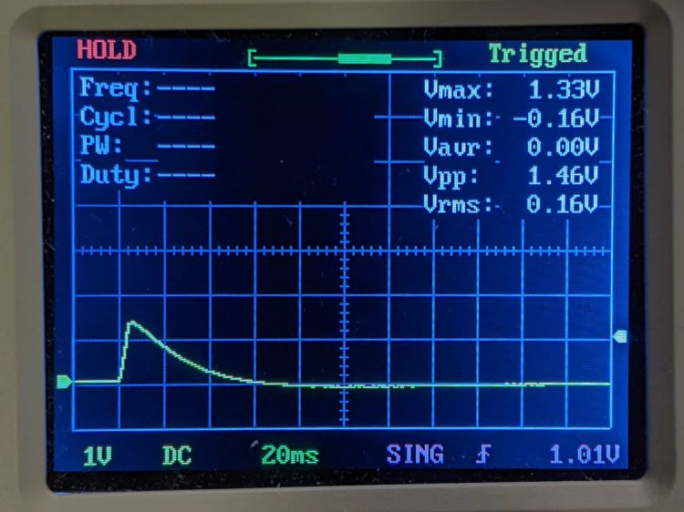
The Gentec ED-200 Joulemeter is severely underqualified to measure the OMTech 60 W laser’s beam power, because the laser’s 1 ms minimum manual pulse width isn’t much shorter than the sensor’s 1.5 ms risetime and the maximum beam power is far too high for the sensor’s health. With that in mind, I set the PWM power to 50% = 30 W (grossly too high) and looked at the peak output voltage for a series of (far too long) pulse widths:
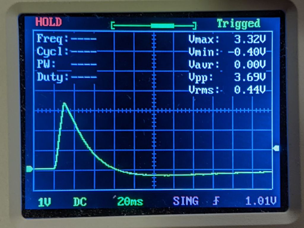
Rounding the detector sensitivity to 11 V/J says the 1.3 V peak at 5 ms corresponds to 120 mJ and 24 W:
Gentec ED-200 – 60W 50pct 5ms
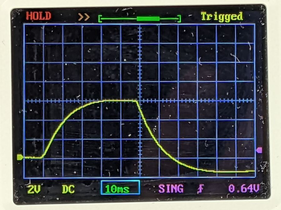
The 3.3 V peak at 10 ms is 300 mJ and 30 W:
Gentec ED-200 – 60W 50pct 10ms
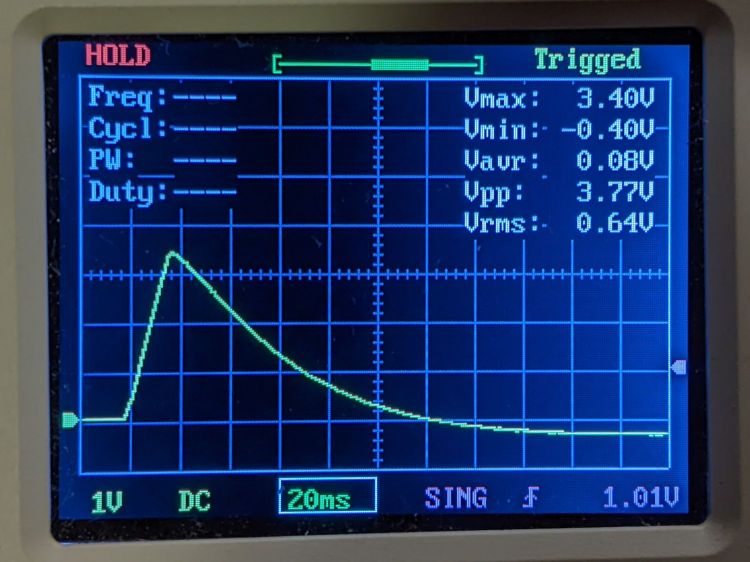
The 3.4 V peak at 15 ms is 310 mJ and 21 W suggests the PWM power output is not nearly as constant as one might expect, although the pulse width looks fine:
Gentec ED-200 – 60W 50pct 15ms
The 6 V peak at 20 ms is 550 mJ and 27 W, although the on-screen display obscures the top:
Gentec ED-200 – 60W 50pct 20ms OSD
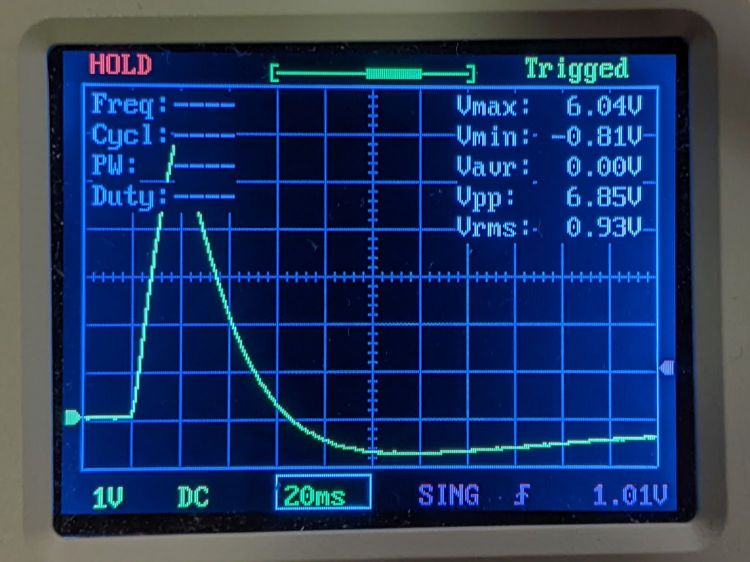
Another 20 ms pulse without the OSD produces a peak eyballometrically close to 6.4 V for 580 mJ and 29 W:
Gentec ED-200 – 60W 50pct 20ms
The KT332N controller in the OMTech 60 W laser has a pulse duration setting showing tenths of a millisecond, but (based on some additional measurements) the beam power can vary by 25% for successive pulses in the low millisecond range, so the pulse width resolution doesn’t seem to provide useful control.
Despite the over-long pulses, the calculated power corresponds surprisingly well with the nominal laser output power.
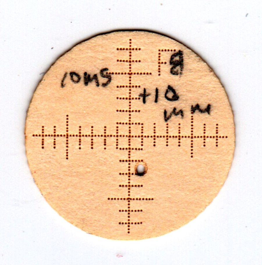
The 1 ms pulses used in LightBurn’s Dot Mode are consistent enough to punch essentially identical 0.2(-ish) mm holes in manila paper to mark the graticule:
They’re on 0.25 mm centers, with slight variations showing the difference between stepper resolution and positioning accuracy. The shorter graticule lines have three holes on one side of the center lines and four on the other, despite the design’s 1 mm length on both sides; I think there’s a missing dot on the side where the head starts the line, perhaps due to a picket-fence error.
The large beam hole came from two 10 ms pulses, one at the focal point and another 10 mm lower.
During the last snowstorm of the season, the venerable MTD snowthrower carved a trench out of the garage and across the driveway, then abruptly stopped moving. The motor roared and the auger turned, but the drive clutch handle had no effect, so I dragged its carcass into the garage and we completed the mission by hand.
Popping the belly plate on the next sunny day revealed the problem: the jam nut (part 34) anchoring the Friction Disk Wheel (part 28) to the Friction Wheel Bracket Assembly (part 32) had gone missing:
MTD Snowblower – page 26 – friction drive parts
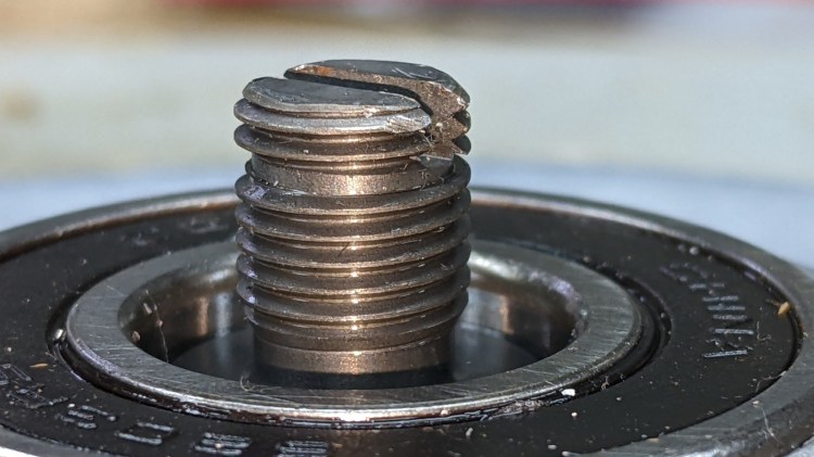
Worse, the Wheel’s threaded shaft spent some time rattling around in the Bracket while chewing up its thread:
MTD Snowthrower – friction disk wheel – damaged thread
This would ordinarily be No Big Deal, but what you see of the shaft is all you get: it rotates freely in the bearing embedded in the Wheel with no way to hold it while cleaning up its threads.
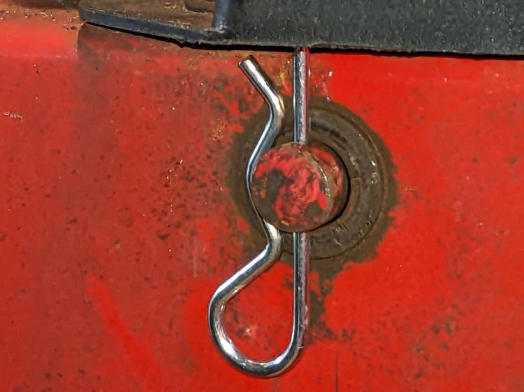
Having already promised to replace the Wheel, I installed the new Wheel using a castle nut secured with a generous dollop of red Loctite, then tapped two of its castellations into the shaft’s slot as a mechanical anchor:
MTD Snowthrower – friction disk wheel – castle nut
I really wanted to lay a nice hard roll pin along that slot through the nut, but there’s no convincing way to secure such a thing without a second nut. Maybe next time?
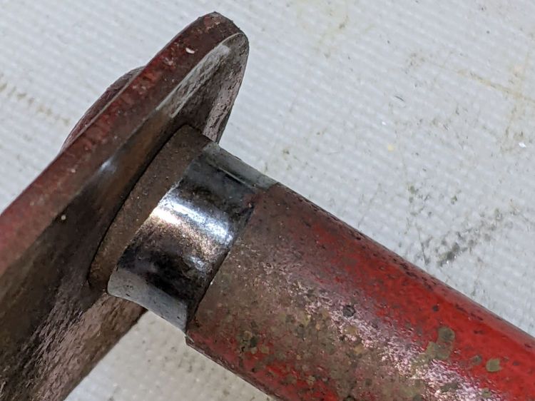
While I had the drive train apart, the sad state of the Wheel Shift Rod Assembly (part 29) became apparent:
MTD Snowthrower – wheel shift rod – worn
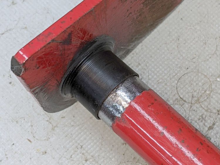
I scuffed up the shiny wear mark, turned a suitable acetal bushing, filled the trench with epoxy, and squished the bushing in place:
MTD Snowthrower – wheel shift rod – acetal bushing
The flange might hold it in place against the Frame Shift Bracket (part 18), which snugly contains the rest of the bushing against the epoxy, so the whole affair might outlast the next season’s first snowstorm. We shall see.


