After eighteen years and one basket / tub replacement, our venerable Kenmore HE3 clothes washer has reached End of Life:


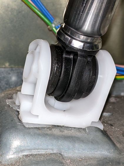
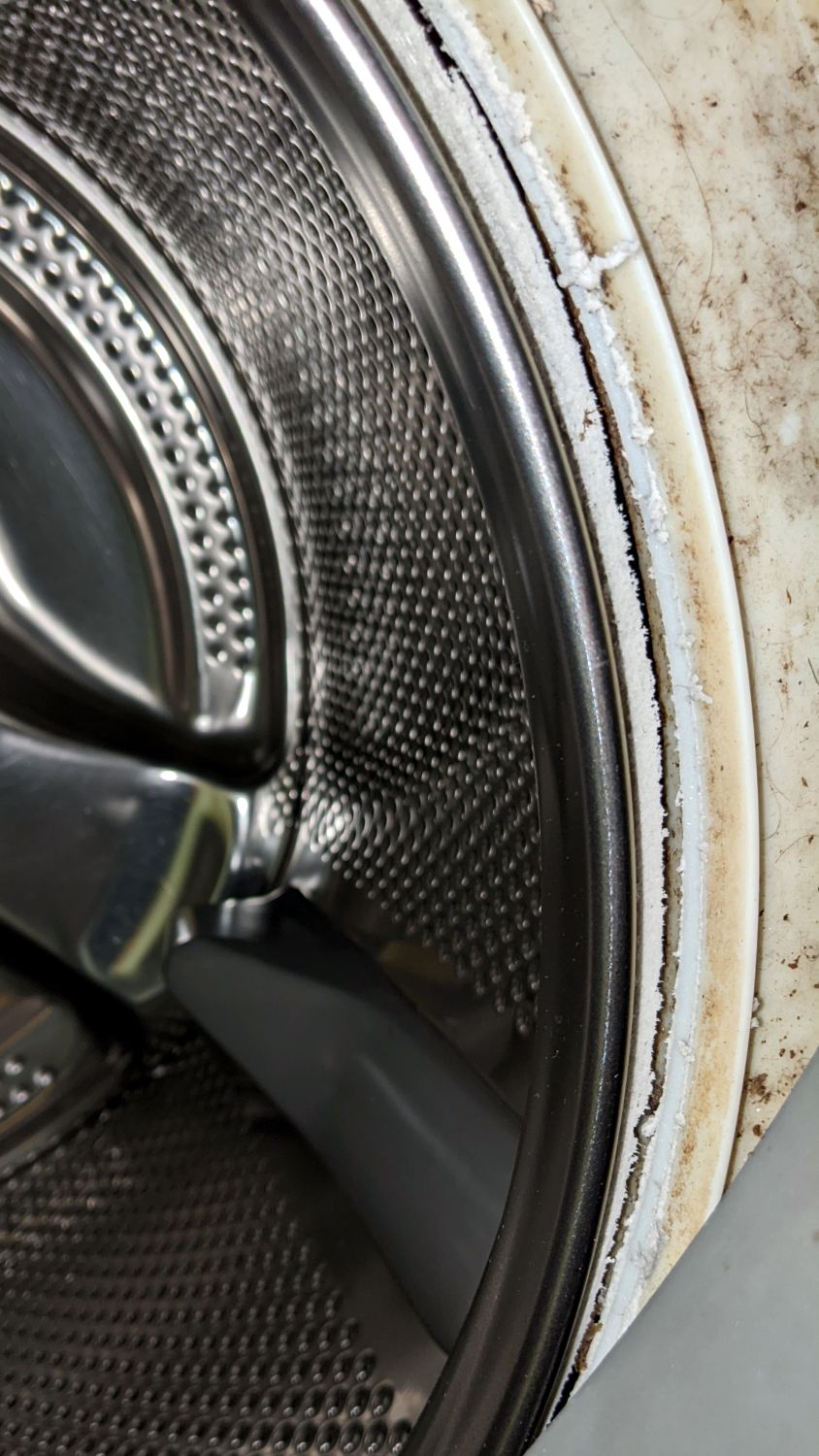
I had looked in there (between the door gasket and the tub) to find any foreign objects making the horrible noise and again, perhaps a week later, when I replaced the shock absorbers, after which the corroded spider in the back finally broke enough to let the basket flop around continuously during the spin cycle and erode the tub rim.
In round numbers, we heard the first sign of trouble three weeks ago: a very loud, but only occasional, KLONK due to protrusions on the side of the basket or the fractured part of the spider on its back hitting indentations in the tub. The KLONK remained intermittent during half a dozen loads, until it became pretty much continuous.
We installed the washer in early 2004, replaced the tub and basket in 2010, and it’s now 2022: the first spider failed after six years and its replacement lasted twelve. After nearly two decades, the tub and basket are no longer available from the usual appliance part sources, so (even if I wanted to) I cannot repair the washer.
Another washer, also a front-loader, also highly rated, will arrive shortly. For the first time ever, we bought an Extended Service Plan good for five years. The alert reader will note the difference between the first failure and the length of the plan, but reviews of similar new machines suggest having Lemon Replacement coverage. In this situation, I am willing to pay for the talismanic effect of coverage that may never pay off, if that makes any sense.