Ed Nisley's Blog: Shop notes, electronics, firmware, machinery, 3D printing, laser cuttery, and curiosities. Contents: 100% human thinking, 0% AI slop.
Tag: Thing-O-Matic
Using and tweaking a Makerbot Thing-O-Matic 3D printer
You’ve probably seen this exchange on whatever DIY 3D printing forum you monitor:
My stepper motors get scorching hot, what should I do?
Turn down the current!
That worked great, but …
… now all my objects have a shift in the middle.
Your motor is losing steps: turn up the current!
Uh, right.
NEMA 17 Stepper on cloth
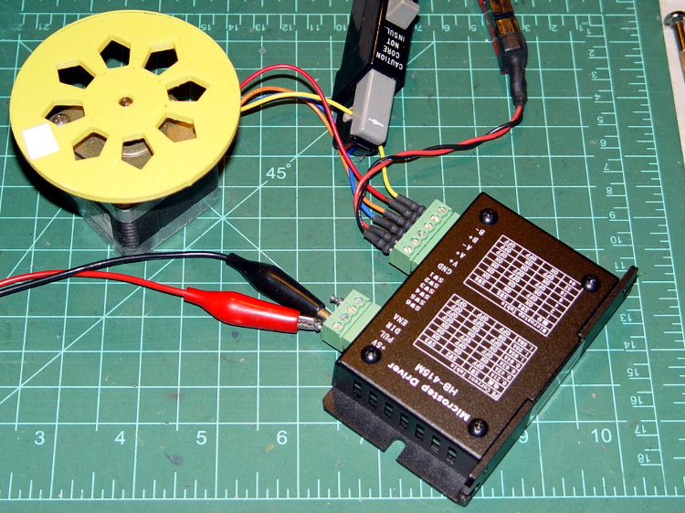
So, with that setup on the bench, I ran a simple experiment with current, temperature, and heat transfer. Most DIY 3D printers have stepper motors attached to a plywood chassis or plastic holder, so the first data point comes from a motor with no mechanical thermal path to the outside world (which is the Basement Laboratory at 14 °C ambient).
Running at about 1200 step/s with a winding current of 1 A peak from a 24 A supply, the motor stabilized at 52 °C = 125 °F after half an hour.
Both windings have a 2 Ω resistance and carry 1 A peak = 0.7 A rms, so the total power dissipation is:
2 × [(1 A / √2)2 × 2 Ω] = 2 W
That’s the same power produced with the motor stopped at a full step position, where the peak current flows in a single winding and the other winding carries zero current:
(1 A)2 × 2 Ω = 2 W
The temperature rise suggests a thermal coefficient of about 19 °C/W = (52 °C – 14 °C) / 2 W.
The next current setting on the driver is 1.46 A, which doubles the power dissipation to 4.3 W. Assuming a large number of linearities, that would cook the motor at 82 °C = 180 °F above ambient. Even though the motor could probably withstand that temperature, for what should be obvious reasons I didn’t go there.
Instead, I parked the motor atop a big CPU heatsink harvested from an obsolete PC, sans thermal compound, mechanical fitting, and anything more secure than gravity holding it in place:
NEMA 17 Stepper on Heatsink
The results:
Ambient
14
°C
Winding
2
ohm
A pk
A rms
Power W
Case °C
°C/W amb
°C/W incr
1.00
0.71
2.0
28
7.0
7.0
1.46
1.03
4.3
42
6.6
6.2
1.91
1.35
7.3
63
6.7
6.9
The thermal coefficients represent the combination of all interfaces from motor case to ambient, but the case and heatsink stabilized to about the same temperature, so the main limit (as always) will be heat transfer to ambient air. Obviously, the heatsink sits in the wrong orientation with little-to-no air flow, not to mention that the butt end of a stepper motor isn’t precisely machined and has plenty of air between the two surfaces. Improving all that would be in the nature of fine tuning and should substantially lower the coefficient.
What’s of interest: just perching the motor on a big chunk of aluminum dropped the case temperature 24 °C without no further effort.
Blowing air over the case (probably) won’t be nearly as effective. Epoxy-ing a liquid-cooled cold plate to the end cap would improve the situation beyond all reasonable bounds, plus confer extreme geek cred.
Hmmm, the Warehouse Wing does have some copper tubing…
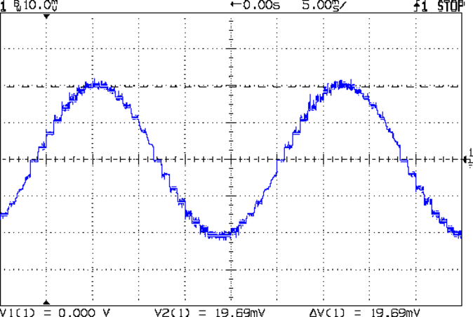
As you saw earlier the low-speed waveform looked reasonably good, although the HB-415M driver produces only 71% of its rated current (so it’s actually 1 A peak, not the 1.5 A in the caption):
HB-415M 8-step 1.5A 20V
The driver runs in 1/8 microstep mode, which means 1 revolution = 8 × 200 step = 1600 steps. Each cycle of that stepped sine wave has 32 microsteps = 4 full steps/cycle × 8 microsteps. One cycle is about 27 ms, so 1 step = 840 µs → 1200 step/s → 0.74 rev/s → 44 rpm. The Thing-O-Matic runs at 47 step/mm → 34 mm/rev, so this speed corresponds to travel at 25 mm/s, roughly the usual printing pace.
Admittedly, that hairball on the bench isn’t a realistic arrangement, because the motor runs with no load. On the other paw, assuming you’ve done a good job eliminating mechanical binding, then it’s probably pretty close to what you’d see during constant-speed travel.
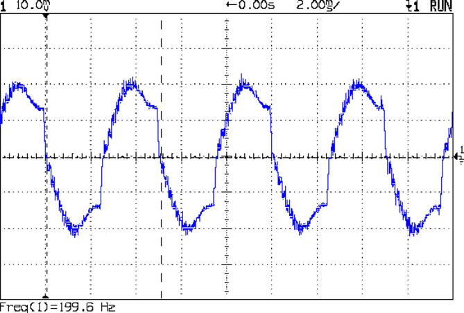
Cranking the pulse generator to 6400 step/s = 133 mm/s produces this waveform:
HB-415M 1A 8step 24V
The power supply was 24 V, but there was no visible difference at 20 V. The driver evidently can’t control the winding current on the downward side of the waveform. Adding some frictional torque by grabbing the yellow interrupter wheel improved the situation, but not by much.
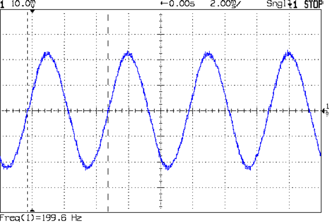
A box of 2M542 drivers just arrived from a nominally reputable supplier, although they were actually labeled M542ES. Under the same conditions, they produce this waveform:
M542ES 1A 8step 24V
So there’s something to be said for larger drivers; the HB-415M drivers were operating at their upper limit and the M542ES at their lower limit, both producing close to 1 A peak.
Strange though it may seem, the kitchen faucet handle broke while Mary was using it. The rear wall of the socket that fits over the cartridge valve stem fractured:
American Standard Faucet Handle – broken mount
Having no water in the kitchen is not to be tolerated, so I applied a redneck fix while pondering the problem:
Kitchen Faucet – redneck handle repair
Based on that comment, I called the American Standard hotline (800-442-1920), described the situation, and they’re sending a replacement handle and cartridge. Evidently the new handle won’t fit the old cartridge, which makes me feel better about not stockpiling repair parts, even while I now wonder what the new cartridge part number might be and how you’d tell them apart.
Anyhow, the redneck fix wouldn’t suffice for the next week; I needed something slightly more permanent. The broken wall fit neatly in place on the mount, but:
It must withstand far more force than a simple glue joint can provide
I can’t machine square holes
Wrapping a metal sleeve around the mount seemed like too much work
You undoubtedly saw this coming a while ago:
Am Std Faucet Handle Sleeve – solid model
The mount tapers slightly from the handle body toward the open end to provide draft for the molding process. I applied a hull() operator to two thin rectangles spaced the right distance apart along the Z axis to create a positive model of the mount, which then gets subtracted from the blocky outer rectangle. The hole clears a 10-32 screw that fits the standard setscrew threads (normally hidden behind the handle’s red-and-blue button).
Unlike most printed parts I’ve done recently, the sleeve suffered from severe shrinkage along the outside walls:
Faucet handle sleeve – build distortion
The inside maintained the right shape, so I cleared the nubs with a file and pressed it in place around the mount with the rear wall snapped into position. The black plastic socket evidently isolates the handle from the valve stem and I used a stainless 10-32 screw to prevent the nightmare scenario of having the sleeve slide downward along the tapered mount and block the setscrew. Overall, it came out fine:
American Standard faucet handle – compression sleeve
However, the chunky sleeve didn’t clear the opening in the escutcheon cap, which put the cap on the windowsill for the next week. The result works much better than the redneck fix and looks almost presentable. It’s certainly less conspicuous:
American Standard faucet handle – temporary repair
I hope the new handle has a much more robust socket…
The OpenSCAD source code:
// Quick fix for broken American Standard Elite 4454 faucet handle
// Ed Nisley KE4ZNU February 2013

//- Extrusion parameters must match reality!
//  Print with +2 shells and 3 solid layers

ThreadThick = 0.25;
ThreadWidth = 2.0 * ThreadThick;

HoleFinagle = 0.4;
HoleFudge = 1.00;

function IntegerMultiple(Size,Unit) = Unit * ceil(Size / Unit);
function HoleAdjust(Diameter) = HoleFudge*Diameter + HoleFinagle;

Protrusion = 0.1;           // make holes end cleanly

//----------------------
// Dimensions

Wall = 5.0;

Slice = ThreadThick;                // minimal thickness for hull object

ShaftEnd = [11.6,17.8,Slice];
ShaftBase = [12.1,18.8,Slice];
ShaftLength = 19.0;

Block = [(ShaftBase[0] + 2*Wall),(ShaftBase[1] + 2*Wall),ShaftLength - Protrusion];

ScrewOffset = 6.5;          // from End
ScrewDia = 5.0;             // clearance

//----------------------
// Useful routines

module ShowPegGrid(Space = 10.0,Size = 1.0) {

    Range = floor(50 / Space);

    for (x=[-Range:Range])
        for (y=[-Range:Range])
            translate([x*Space,y*Space,Size/2])
            %cube(Size,center=true);

}

module PolyCyl(Dia,Height,ForceSides=0) {           // based on nophead's polyholes
  Sides = (ForceSides != 0) ? ForceSides : (ceil(Dia) + 2);
  FixDia = Dia / cos(180/Sides);
  cylinder(r=HoleAdjust(FixDia)/2,h=Height,$fn=Sides);
}

//----------------------
// Model the handle's tapered shaft

module Shaft() {

    hull() {
        translate([0,0,ShaftLength - Slice/2])
            cube(ShaftEnd, center=true);
        translate([0,0,Slice/2])
            cube(ShaftBase, center=true);
    }

}

//----------------------
// Build it!

ShowPegGrid();

difference() {
    translate([0,0,ShaftLength/2])
        cube(Block,center=true);
    Shaft();
    translate([0,0,ShaftLength - ScrewOffset])
        rotate([-90,0,0])
            PolyCyl(ScrewDia,ShaftBase[1],6);
}
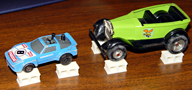
For reasons that undoubtedly make sense to him, my buddy Aitch is moving to coastal NC. Seeing as how we lived in Raleigh for half a decade, I figure he needs some hints on how to blend in…
Toy cars up on blocks
The solid model looks about the way you’d expect:
Concrete block – solid model
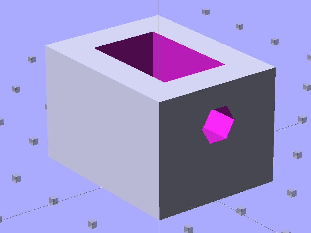
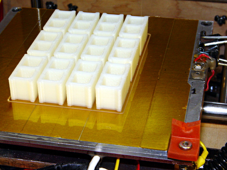
The webs are slightly thinner than in real life, but it looks OK to me. The web came out slightly over 3 thread widths = 1.5 mm, to ensure they get a bit of fill rather than being two distinct threads. I originally tried making the web exactly 3 threads wide, which produced tiny dots of fill on the sides and corners. They printed with 0.20 infill; they’d print faster with 1.00 infill or all-solid layers.
You’ll want to create a pile o’ blocks at once, of course, although this array took about two hours:
Concrete blocks – build platform
The OpenSCAD source code:
// Scale model concrete block
// Ed Nisley KE4ZNU February 2013

// Extrusion parameters must match reality!
// Print with +0 shells and 3 solid layers

ThreadThick = 0.25;
ThreadWidth = 2.0 * ThreadThick;

function IntegerMultiple(Size,Unit) = Unit * ceil(Size / Unit);

Protrusion = 0.1;           // make holes end cleanly

//----------------------
// Dimensions

Scale = (1/25) * (3*ThreadWidth);

BlockWidth = Scale * 190;
BlockLength = Scale * 390;
BlockHeight = BlockWidth;

WebWidth = Scale * 30;

CoreSize = [(BlockWidth - 2*WebWidth),(BlockLength - 4*WebWidth)/2,BlockHeight];

CornerRadius = WebWidth/2;

//----------------------
// Useful routines

module ShowPegGrid(Space = 10.0,Size = 1.0) {

    Range = floor(50 / Space);

    for (x=[-Range:Range])
        for (y=[-Range:Range])
            translate([x*Space,y*Space,Size/2])
            %cube(Size,center=true);

}

//-------------------
// Component parts

module Core(Size,Radius) {
    translate([0,0,(Size[2] - Protrusion)/2])
        minkowski() {
            cube([(Size[0] - 2*Radius),(Size[1] - 2*Radius),Size[2]],center=true);
            cylinder(r=Radius,h=Protrusion,$fn=8);
        }
}

//----------------------
// Build it!

ShowPegGrid();

difference() {
    translate([0,0,BlockHeight/2])
        cube([BlockWidth,BlockLength,BlockHeight],center=true);
    for (i = [-1,1])
        translate([0,i*(CoreSize[1] + WebWidth)/2,0])
           Core(CoreSize,CornerRadius);
    for (i = [-1,1])
        translate([0,i*3*(CoreSize[1] + WebWidth)/2,0])
           Core(CoreSize,CornerRadius);
}
Three rack protectors have gone missing over the last few months, presumably being digested by the dishwasher’s grinder, so I ran off another batch:
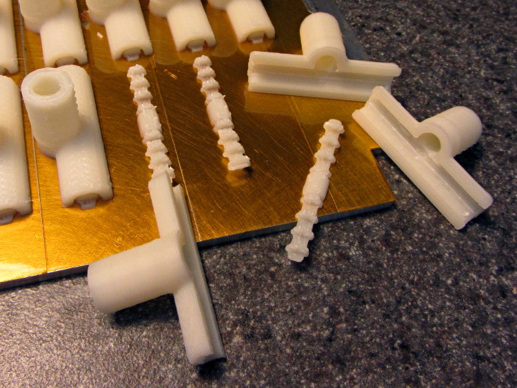
Dishwasher Rack Protectors – on platform
I used the original solid model, shown here with the support structure outside for visibility:
Dishwasher rack protector – support model
I re-sliced the model to pick up whatever printer config tweakage happened since then. Those ribbed doodads snapped out easily and, in fact, some remained bonded to the platform:
Dishwasher Rack Protectors – support structures
No finishing required: just slide them over the pins atop a blob of acrylic caulk. Despite the few missing protectors, it does a good job of bonding them to the rack and sealing gaps in the worn vinyl coating.
I picked up a jar of ReRack glop on closeout duing my last pass through the Big Box Home Repair Store. It seemed a bit stiff, so I’ve added generous dollops of xylene, acetone, and MEK to thin it out; that’ll take a while to stabilize.
After beating the Samsung’s nozzle handle and hose into submission, I made a set of floor brush strips for the hard-floor attachment:
Floor brush strips – replacements in place
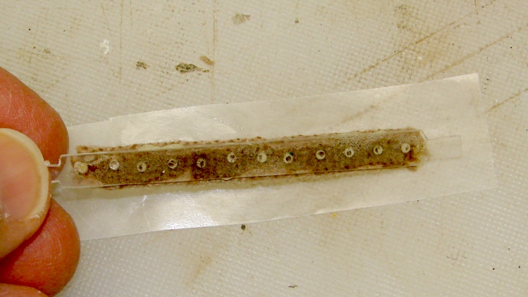
The original brushes had non-woven felt glued to a cleverly molded strip of white plastic, which lasted not very long at all. I’d replaced them (*) with wool fabric glued to hand-hewn strips of polypropylene cut from the usual blister pack material, but that was so labor-intensive as to make no sense at all; it did show that replacement brushes would work, though, which was the whole point. This view looks through a finished strip to the urethane glue and wool fabric:
Floor brush strip – manual version
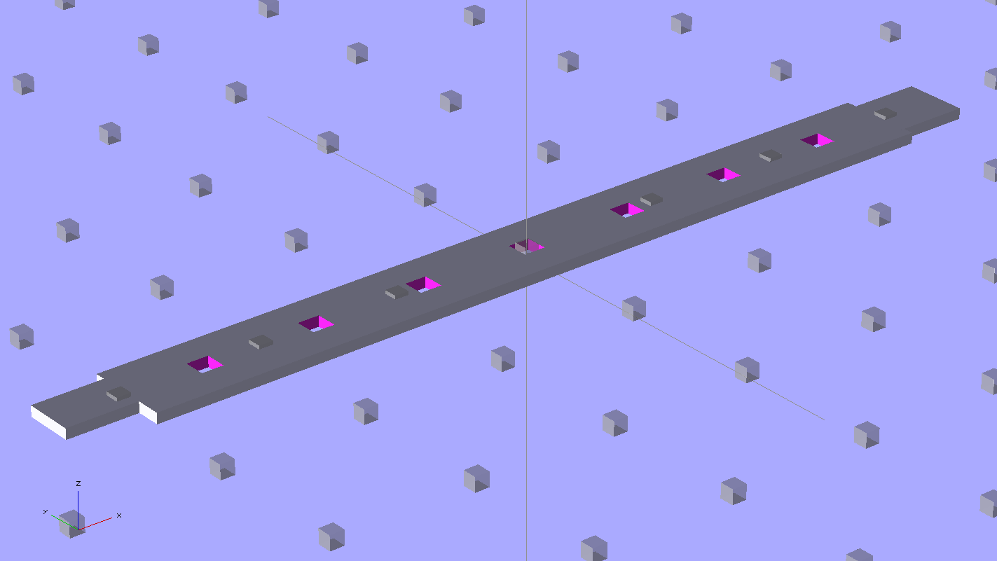
Fortunately, there’s an easier way to make the strips:
Floor brush strip – solid model
Note that the smaller tab (the one in the front) is not centered on the midline. The openings for the larger tab in the floor brush housing seem to have a small offset, but it’s not worth worrying about. The printed ones are 4 layers thick, but I think 3 layers will work as well; that’s what the OpenSCAD source will produce.
This is one of the few situation where the hand-knitted top surface of a 3D-printed object is an advantage: that, plus the holes, provides enough griptitude for urethane glue to hold the fabric strips firmly in place.
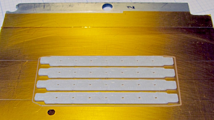
Obviously, you print them in multiples:
Floor brush strips – on platform
A trial fit:
Floor brush strip – trial fit
They really are bowed slightly outward in the middle, which ensures there’s more pressure on the middle of the strip against the floor. I think the weird indented pattern in the brush housing under the strips was for a complex spring assembly that never made it into production; the OEM strips looked just like the ones I’m making, minus the perforations.
I glued two strips individually to make sure everything lined up, then glued these two in one operation and separated them with a razor knife:
Floor brush strips – gluing fabric
(*) It goes without saying that OEM replacement brushes weren’t available and, in fact, they have never been available at any time when we’ve owned the vacuum cleaner. Maybe I’m not looking in the right place, but so it goes.
The OpenSCAD source code, which you’ll want to print with Multiply set to maybe 8:
// Samsung Vacuum cleaner nozzle floor strips
// Ed Nisley KE4ZNU January 2013

Layout = "Build";			// Show, Build

//- Extrusion parameters must match reality!
//  Print with +0 shells and 3 solid layers

ThreadThick = 0.25;
ThreadWidth = 2.0 * ThreadThick;

HoleWindage = 0.75;

function IntegerMultiple(Size,Unit) = Unit * ceil(Size / Unit);

Protrusion = 0.1;           // make holes end cleanly

//----------------------
// Dimensions

Body = [6.0,59.0,3*ThreadThick];	// width, length, thick

Tab1 = [4.5,5.0,0.0];				// width, length, offset from centerline
Tab2 = [3.5,5.0,0.5];

HoleOC = 8.0;						// adhesive anchoring holes
HoleDia = 1.0;
HoleSides = 4;
HoleMax = floor(Body[1]/(2*HoleOC));

echo("HoleMax: ",HoleMax);

//----------------------
// Useful routines

module PolyCyl(Dia,Height,ForceSides=0) {           // based on nophead's polyholes

Sides = (ForceSides != 0) ? ForceSides : (ceil(Dia) + 2);

FixDia = Dia / cos(180/Sides);

cylinder(r=(FixDia + HoleWindage)/2,
         h=Height,
         $fn=Sides);
}

module ShowPegGrid(Space = 10.0,Size = 1.0) {

    Range = floor(50 / Space);

    for (x=[-Range:Range])
        for (y=[-Range:Range])
            translate([x*Space,y*Space,Size/2])
            %cube(Size,center=true);

}

module BackingStrip() {

	difference() {
		union() {
			translate([0,0,Body[2]/2])
			cube(Body,center=true);
			translate([Tab1[2],-1*Body[1]/2,Body[2]/2])
			cube([Tab1[0],2*Tab1[1],Body[2]],center=true);
			translate([Tab2[2],+1*Body[1]/2,Body[2]/2])
			cube([Tab2[0],2*Tab2[1],Body[2]],center=true);
		}
		for (i = [-HoleMax:HoleMax])
			translate([0,i*HoleOC,-Protrusion])
			rotate(45)
			PolyCyl(HoleDia,(Body[2] + 2*Protrusion),HoleSides);
	}
}

//----------------------
// Build it!

ShowPegGrid();

if (Layout == "Show")
	BackingStrip();

if (Layout == "Build")
	rotate(90) BackingStrip();
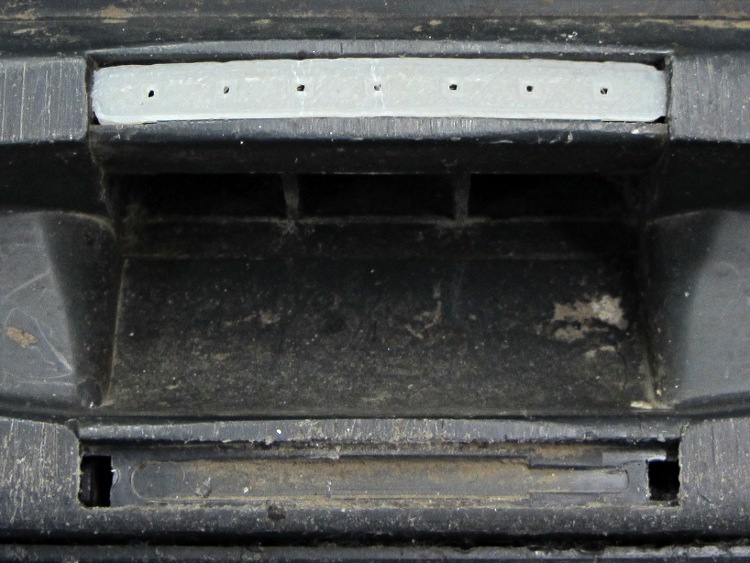
The hose going into the handle of the never–sufficently-to-be-damned Samsung VAC-9048R suck dog has been collapsing for quite some time, but I couldn’t figure out how to take the handle apart. Recently, the lock ring that I would have sworn was glued in place came loose, revealing the secret:
Samsung vacuum cleaner – handle lock ring
You slide four lugs on the lock ring into the open slots, then turn the ring clockwise to force the lugs over barriers into recesses that capture them and hold the lock ring against the handle. The handle under the lock ring isn’t quite circular, nor is the lock ring, and I think (based on later events) that they expect the ring to deform as it turns in order to let the lugs spring over the barriers.
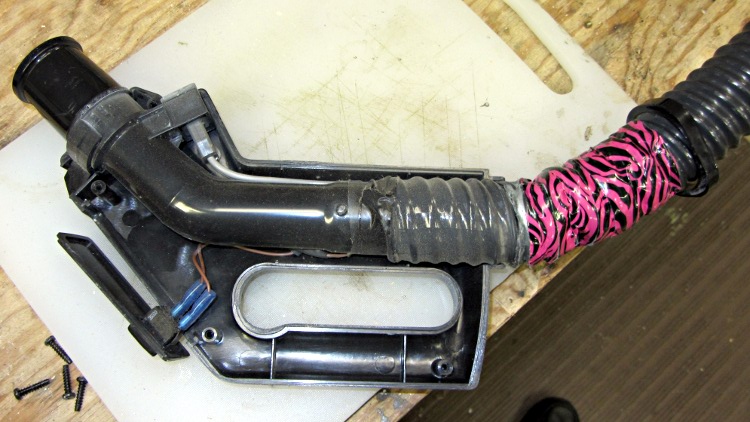
Anyhow, with the lock ring loose, removing four screws released the two halves of the handle:
Samsung vacuum cleaner – handle interior
The handle includes a switch for the powered floor brush, which we rarely use, and a suction control lever that’s basically a binary leak: on or off. With the handle opened in front of you, remove the innards, unwrap the decorative duct tape, unwind enough of the two power conductor / spring wire ribs to allow for rebuilding the electrical connections, and cut off the damaged part of the hose.
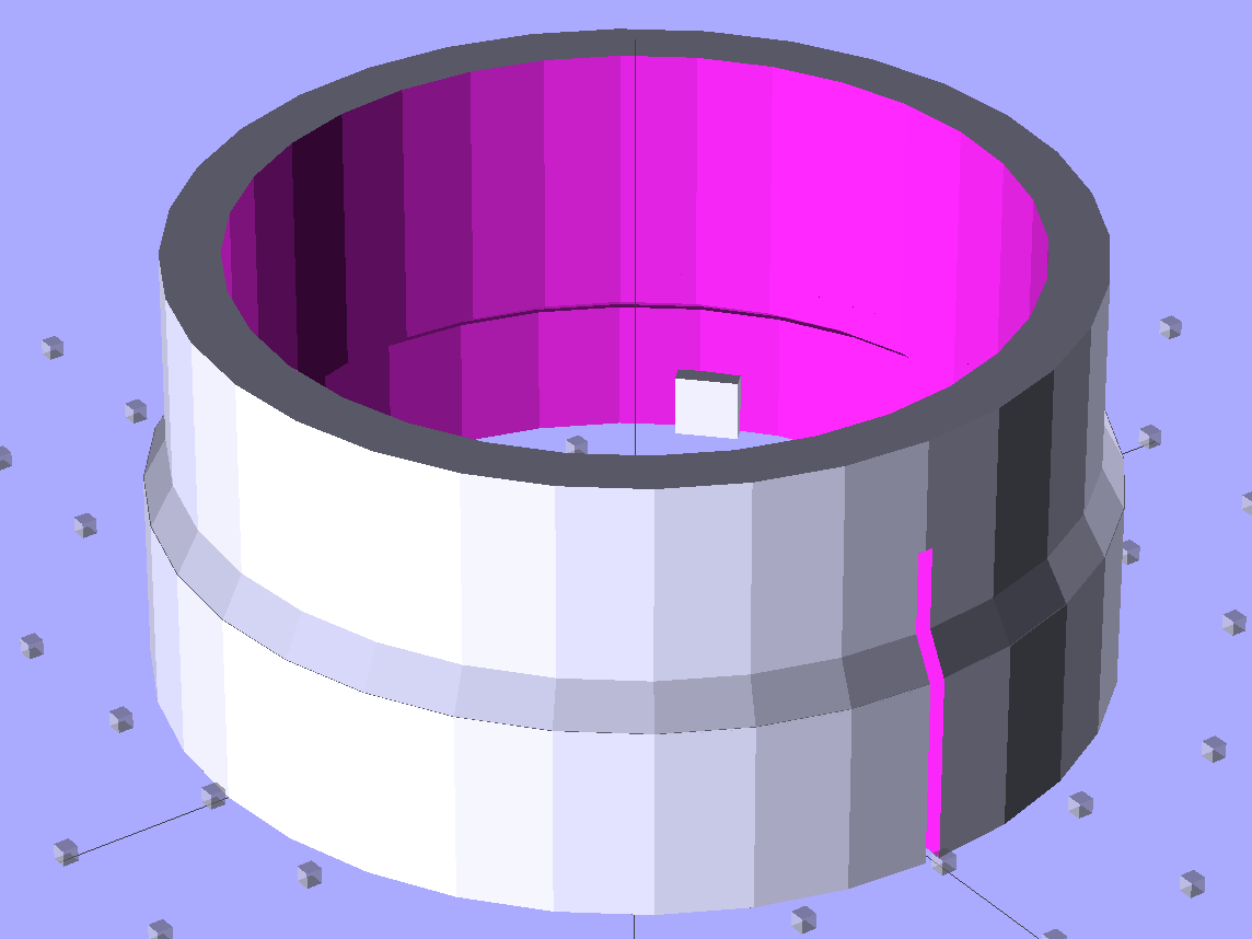
Now, obviously, what that hose needs is a little bit of strain relief, along the lines of the hideous snout I’d affixed to its other end a while ago. The general idea is to replace the lock ring with a little attachment that will hold the heatshrink tubing in place. Something like this:
Bushing Solid Model – top
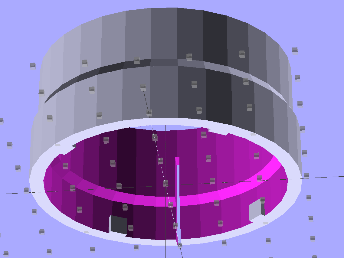
The bottom view, looking up through the layer of 1 mm cubes defining the Z=0 plane, shows the lugs:
Bushing Solid Model – bottom
I thought the slit would provide enough springiness to let the lugs bump over the ridges, but it wasn’t quite enough: the relatively stiff ABS isn’t nearly as springy as the original black plastic for about the same thickness. For the next version, I’ll try four slits, all of which must end at different levels to avoid concentrating the stress on a single layer.
In any event, it came out about like you’d expect:
Handle Bushing – on platform
As with many projects, though, I had to make a pair of simpler prototypes to get the measurements correct. The lugs, for example, are not 90° apart, spaced neatly around the handle’s midline seam, as I assumed for Prototype 1 on the right:
Handle bushings – prototypes 2 and 1
Prototype 2, on the left, has a support structure holding up a horizontal step that butted against the handle, which turned out to be unnecessary. The OpenSCAD version substitutes a pair of conical transitions that worked much better; they’re at different levels with a thicker wall section between them.
With the ring and somewhat preshrunk heatshrink tubing slipped along the hose, rewiring proceeds in reverse order. Next time, I’ll add a QD fitting in the hose-to-socket wire so I can take the whole thing apart again without cutting that wire:
Samsung Vacuum Handle – wiring detail
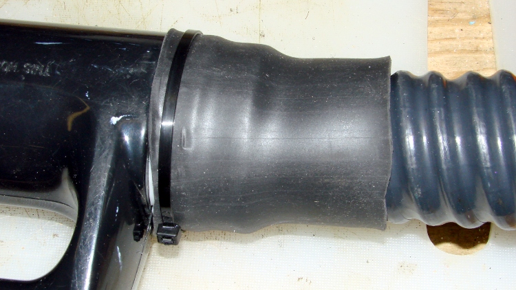
Assemble the handle, snap the glaring white strain relief fitting in place, shrink the tubing, add a cable tie mostly for show:
Samsung Vacuum Handle – heatshrink over bushing
I cut a few slits in the tubing’s end to improve its bendiness, but it’s already Much Better than it was.
A few things I’d do differently:
Add a recess for the cable tie, with a flat spot for its latch
Four slits, not just one
Ribs on the snout to help anchor the tubing
Longer snout?
The OpenSCAD source code for the final version, with a module for the support ring that you won’t need:
// Samsung Vacuum cleaner hose bushing
// Ed Nisley KE4ZNU January 2013

// Layout options

Layout = "Build";
                    // Overall layout: Show Build
                    // Parts: Ring Sleeve

//- Extrusion parameters must match reality!
//  Print with +1 shells and 3 solid layers

ThreadThick = 0.25;
ThreadWidth = 2.0 * ThreadThick;

HoleWindage = 0.75;

function IntegerMultiple(Size,Unit) = Unit * ceil(Size / Unit);

Protrusion = 0.1;           // make holes end cleanly

//----------------------
// Dimensions

HoseOD = 47.0;					// spiral tube diameter
TubeWall = 1.4;					// heatshrink tubing wall thickness
HandleRingLong = 8.5;			// length of ring stub on handle

RingID = 51.0;					// lock ring over handle end
RingOD = 58.0;
RingLong = 12.0;

Locks = 4;						// bumps inside lock ring
LockLength = 4.0;
LockWide = 4.0;
LockThick = 0.75;

LockAngleOffset = 52.0;			// offset of lock bump from handle top dead center
LockAngleIncluded = 102.4;		// between first and second lock bump (also 3 & 4)
LockAngles = [-LockAngleOffset,
				-(LockAngleOffset+LockAngleIncluded),
				-(LockAngleOffset+180),
				-(LockAngleOffset+LockAngleIncluded+180)];

BushID = HoseOD + 1.0;			// over spiral hose
BushOD = RingOD - 2*TubeWall;	// allow flush heatshrink fit
BushLength = 15.0;

SlitWidth = 2*ThreadWidth;		// allow expansion of lock ring, sorta kinda
SlitHeight = 20.0;
SlitAngle = 0;
SlitLength = max(RingOD,BushOD);

RingSides = 4*8;
RingAlign = 360/(2*RingSides);
$fn = RingSides;

//----------------------
// Useful routines

module PolyCyl(Dia,Height,ForceSides=0) {           // based on nophead's polyholes

Sides = (ForceSides != 0) ? ForceSides : (ceil(Dia) + 2);

FixDia = Dia / cos(180/Sides);

cylinder(r=(FixDia + HoleWindage)/2,
         h=Height,
         $fn=Sides);
}

module ShowPegGrid(Space = 10.0,Size = 1.0) {

    Range = floor(50 / Space);

    for (x=[-Range:Range])
        for (y=[-Range:Range])
            translate([x*Space,y*Space,Size/2])
            %cube(Size,center=true);

}

//-------------------
// Component parts

module Ring() {
	union() {
		difference() {
			union() {
				cylinder(r=RingOD/2,h=(RingLong + Protrusion));
				translate([0,0,RingLong])
					cylinder(r1=(RingOD/2),r2=(BushOD - Protrusion)/2,h=(RingOD - BushOD));
			}
			translate([0,0,-Protrusion]) {
				PolyCyl(RingID,(HandleRingLong + Protrusion),RingSides);
				cylinder(r=BushID/2,h=(2*RingLong));
			}
			translate([0,0,(HandleRingLong - Protrusion)])
				cylinder(r1=((RingID/2) / cos(180/RingSides) + HoleWindage),
						 r2=BushID/2,
						 h=(RingID - BushID)/2);
		}
		for (i=[0:Locks-1])
			rotate(LockAngles[i] + RingAlign)
				translate([(RingID/2),0,LockWide/2])
					cube([2*LockThick,LockLength,LockWide],center=true);
	}
}

module Sleeve() {
	difference() {
		cylinder(r=BushOD/2,h=(BushLength + Protrusion));
		translate([0,0,-Protrusion])
			cylinder(r=BushID/2,h=BushLength + 3*Protrusion);
	}
}

module Bushing() {
	difference() {
		union() {
			Ring();
			translate([0,0,RingLong])
				Sleeve();
		}
		rotate(SlitAngle)
			translate([SlitLength/2,0,(SlitHeight - Protrusion)/2])
				cube([SlitLength,SlitWidth,(SlitHeight + Protrusion)],center=true);
	}
}

// This turned out to be unnecessary after tapering the transitions
module Support() {

SuppHeight = RingLong - ThreadThick;

	color("Yellow")
	union() {
		difference() {
			cylinder(r=(RingID/2 - LockThick - ThreadWidth/2),h=SuppHeight);
			translate([0,0,-Protrusion])
				cylinder(r=(BushID/2 - ThreadWidth),h=2*RingLong);
			for (i=[0:RingSides-1])
				rotate(i*2*RingAlign)
					translate([RingID/4,0,SuppHeight - ThreadThick/2 + Protrusion/2])
						cube([RingID/2,(LockLength - 3*ThreadWidth),(ThreadThick + Protrusion)],center=true);
		}
	}
}

//----------------------
// Build it!

ShowPegGrid();

if (Layout == "Build")
	union() {
		Bushing();
//		Support();
	}

if (Layout == "Show")
	Bushing();

if (Layout == "Ring")
	Ring();

if (Layout == "Sleeve")
	Sleeve();

if (Layout == "Support")
	Support();