Ed Nisley's Blog: Shop notes, electronics, firmware, machinery, 3D printing, laser cuttery, and curiosities. Contents: 100% human thinking, 0% AI slop.
Tag: Thing-O-Matic
Using and tweaking a Makerbot Thing-O-Matic 3D printer
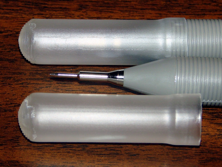
Our Larval Engineer received a logic probe / pulser set for Christmas:
RSR Logic Probe Pulser Set – with formed covers
They’re the low-cost RSR-611 and -620 from the usual eBay vendor, not my ancient HP10525/10526 set, but they should suffice. Perhaps nobody uses logic probes these days, what with most of the parts being too small for even a needle tip, but …
Anyhow, they didn’t have caps over the sharp probe tips, so I rummaged around until I found the stash of cigar tubes (some of which went into that air flow straightener) that were about the right size. I thought about 3D printing an adapter between tubes and probes:
RSR Probe Cap Adapter – solid model
It’s actually a subtractive kind of thing, with a model of the probe tip subtracted from a suitable cylindrical object:
RSR Logic Probe – solid model
But then I realized the tubes were thermoplastic, held each one over a stove burner until the open end went transparent and droopy, rammed it down over the probe tip, and trimmed off the ragged edge. Worked fine, fits securely, and even looks pretty good:
RSR Covers – detail
I’ll never print the adapters, but maybe one of us will tweak the model to do something else…
The OpenSCAD source code:
// RSR Logic Probe / Pulser Cap
// Ed Nisley KE4ZNU December 2012

// Adapts cigar tube to probe body

// Layout options

Layout = "Build";
                    // Overall layout: Show Build
			// Parts: Probe

//- Extrusion parameters must match reality!
//  Print with +1 shells and 3 solid layers

ThreadThick = 0.25;
ThreadWidth = 2.0 * ThreadThick;

HoleWindage = 0.2;

function IntegerMultiple(Size,Unit) = Unit * ceil(Size / Unit);

Protrusion = 0.1;           // make holes end cleanly

//----------------------
// Dimensions

ProbeDia = 18.0;				// dia of main body
ProbeTipDia = 6.8;				// dia at end of plastic cone
ProbeTipLen = 30.0;				// length of metal ferrule + tip
ProbeConeLen = 17.5;			// cone taper length

TubeOD = 17.25;
TubeWall = 0.50;
TubeID = TubeOD - 2*TubeWall;

TubeLen = 15;					// slip fit over tube body

BodyLen = 20;					// slip fit over probe body

WallThick = 3.5*ThreadWidth;		// basic adapter wall thickness

AdapterLen = TubeLen + BodyLen;
AdapterOD = ProbeDia + 2*WallThick;
AdapterSides = 4*4;

//----------------------
// Useful routines

module PolyCyl(Dia,Height,ForceSides=0) {           // based on nophead's polyholes

Sides = (ForceSides != 0) ? ForceSides : (ceil(Dia) + 2);

FixDia = Dia / cos(180/Sides);

cylinder(r=(FixDia + HoleWindage)/2,
         h=Height,
         $fn=Sides);
}

module ShowPegGrid(Space = 10.0,Size = 1.0) {

    Range = floor(50 / Space);

    for (x=[-Range:Range])
        for (y=[-Range:Range])
            translate([x*Space,y*Space,Size/2])
            %cube(Size,center=true);

}

module Probe() {
	union() {
		cylinder(r=((ProbeDia + HoleWindage)/2),
				 h=(BodyLen + 1.2*Protrusion),$fn=2*AdapterSides);
		translate([0,0,(BodyLen + Protrusion)])
			cylinder(r1=(ProbeDia + HoleWindage)/2,
					 r2=ProbeTipDia/2,
					 h=ProbeConeLen,$fn=2*AdapterSides);
		cylinder(r=ProbeTipDia/2,h=(BodyLen + ProbeConeLen + ProbeTipLen),$fn=2*AdapterSides);
	}
}

module ProbeSleeve() {

	difference() {
		cylinder(r=AdapterOD/2,h=AdapterLen);
		translate([0,0,-Protrusion])
			Probe();
		PolyCyl((TubeOD + HoleWindage),(AdapterLen + Protrusion),2*AdapterSides);
	}
}

//----------------------
// Build it!

ShowPegGrid();

if (Layout == "Show")
    ProbeSleeve();

if (Layout == "Build")
    translate([0,0,AdapterLen])
		rotate([180,0,0])
			ProbeSleeve();

if (Layout == "Probe")
	Probe();
With the Bash script and OpenSCAD source in hand, here’s how you go about producing a grayscale image that works as the height map file to produce a cookie press and matching cookie cutter.
The Big Picture description: the grayscale height map image looks a lot like a photo of the final cookie on a plate in front of you. The darkest regions mark the thinnest parts of the cookie: black lines emboss deep trenches. Gray regions denote thicker sections and very light gray will be thickest. Because image files are rectangular, a pure white area surrounds the region that will become the cookie press and acts as a mask to remove the rectangular border.
If you start by hand-drawing the shape of the cookie press at full size inside a 5 inch square (chosen to match the 3D printer’s build platform and in inches because that’s how it got measured; it’s not my printer) with a 1.5 or 2 mm black marker, then the marker lines will be just about exactly the right width to ensure good plastic fill (for a printer producing a 0.5 mm thread width, anyway) and printable walls. You can scale the drawing for smaller (my Thing-O-Matic) or larger (M2, Series One) platforms, but the thread width and minimum wall thickness do not scale: a tiny 1 inch push mold must still have 2 mm walls.
The workflow looks like this:
Draw cookie press lines at full scale with fat black marker on white paper
Scan a 5×5 inch (127×127 mm) square around the image at 300-ish dpi → 1500×1500 pixel image
Convert a full-color scan to grayscale now (better to scan in grayscale)
Resize image to 317×317 pixel, optionally set 2.5 pixel/mm = 63.5 dpi for proper display size
Set color levels to blow out the contrast; auto probably works fine
Threshold to reduce to just two colors: 0% = black and 100% = white
Clean up the image: remove specks and single-pixel bumps, fill small gaps
Some sample images to show what happens along the way…
A hand-drawn image, derived from The Original Tux by crudely tracing the outline with a fat Sharpie, including some areas outside the box for pedagogic purposes:
TuxTrace – raw scan
The interior edge of the black box is exactly 5×5 inches. I created a 5×5 inch blank white image at 300 dpi, enlarged the canvas to 5.2×5.2 inches with the blank white image centered in the middle, set a black background, flattened the image to fill the border, and printed it out. That produces a piece of blank paper with a black square suitable for full-scale drawing.
It does not, however, confer any artistic eptitude whatsoever, so for this drawing I imported one of the Tux drawings, isolated the edges with one of The GIMP’s edge detectors, and traced over the thin lines with the aforementioned fat Sharpie. You can draw whatever you want, however you want it. If you already have an image file, you need not print it out and scan it back in; just resize it appropriately.
Pro tip: Ensuring that the drawing doesn’t touch the black square will greatly simplify the next half hour of your life.
A note on Sharpies. I used a Fine Point Marker, which is much fatter than a Fine Point Pen. The whole, uh, point is to produce a line about 2 mm wide that will become an actual plastic wall; you can’t print anything much finer than that.
A note on blackness. There’s no requirement for any black lines whatsoever. For most cookie presses, however, you want distinct walls that emboss lines into the dough, which is what the black lines will do. If you want to mold a cookie (or anything else, like a butter pat), you can produce a gently curved push mold by using only grayscale areas. For example, a circular area with a radial fill going from very light gray on the exterior to very dark gray in the center will produce a round cookie with a conical dent in the middle.
Given a drawn image, scan the area just inside the black square at 300 dpi to produce a nominally 1500×1500 pixel image, then resize it to 317×317 pixel at 63.5 dpi:
TuxTrace – crop resize
The magic number 317 comes from not wanting OpenSCAD to fall over dead after chewing on a larger image for an hour or two. Given the restriction to maybe 330×330 pixels, max, I picked a nice round 2.5 pixel/mm scaling factor that converts a 5 inch = 127 mm distance into 317 pixels:
317 pixel = 127 mm x 2.5 pixel/mm
The magic number 63.5 comes from wanting the image to print (on paper) and display (on screen) at the proper size:
5 inch = 317 pixel / 63.5 pixel/inch
Given a properly sized image, blow out the contrast so the background is mostly white and the lines are mostly black. This gets rid of background cruft:
TuxTrace – color levels
Then apply a threshold to get rid of all the gray levels. The threshold level determines the line width (the edges shade from black to gray to white), so you can tune for best width. The result doesn’t look much different than the blown contrast version, but the lines will become thinner and more jagged. Remember that you want the lines to be at least three pixels wide:
TuxTrace – threshold
Do whatever cleanup is required; eliminate single-pixel bunps and dents, fatten (or, rarely, thin) lines as needed. If you draw with a 3 pixel wide pen, the line will print just over 1 mm wide, which is about the thinnest possible wall and may encounter problems at corners. Use pure 0% black and pure 100% white.
If you possess powerful art-fu, you can draw that kind of image directly in the graphics program. Those of us with weak art-fu must rescale a found image of some sort. Should you draw a new image or rescale an old one, then:
Start with a 317×317 pixel grayscale canvas in 100% white
Draw lines with a 3 pixel (probably a square) 0% black pen
Now you have a clean black and white image of the cookie press lines; it’s still a grayscale image, but using only two colors.
Use color levels to reduce the white to about 95% gray; this avoids interior islands
Bucket-fill the exterior with 100% white (interior remains 95%): no anti-aliasing or blending
Fill interior regions with grays to set cookie press depths: dark = low, light = high, no 100% white, no anti-aliasing
Save as PNG to avoid compression artifacts
By reducing the overall white level to 95%, you get rid of all that pure white in the whole interior. Remember that pure white marks the area outside of the press, so any white inside the press will produce bizarre islands. You could pour 95% white into all the interior areas, but if you miss one, you have an island.
Having reduced all the whites, pouring pure 100% white around the press restores the exterior mask color. Turn off the anti-aliasing / blending / feathering options, because you want crisp edges rather than nice-looking gray transitions.
If all you want is a press with lines, you’re done. Save the image and proceed to make the cutter & press.
If you want a press that produces a cookie with different thicknesses, do some gray pours. For example:
TuxTrace – grayscale height map
That’s obviously contrived, but the general idea is that the feet and beak will be the thickest part of the cookie, the tummy next, and the body will be the thinnest part. The glint above one eye will become a bizarre peak, but that’s to show why you probably don’t want to do that. It’s not obvious, but the eyeball pupil and sclera areas will be recessed into the body.
If you’re doing a push mold, elaborate grayscaling will make a lot more sense. For a cookie press, black is where it’s at.
That process produces a clean grayscale image. Save it as a PNG file to avoid JPEG image compression artifacts: you want crisp lines and flat areas that define heights, not a small file. It’ll be small enough, anyway, compared to the eventual STL files.
To review, the grayscale height map image must satisfy this checklist:
Maximum 317×317 pixels: smaller is OK and will print at 2.5 pixel/mm; larger may not work
Exterior pure white: 100% = 255/255
Four corners must be 100% white to allow proper auto-cropping
No interior pixels are 100%: at most 99.6% = 254/255 will be fine
All lines at least 3 pixels wide: will print at 1.2 mm = (3 pixel / 2.5 pixel/mm)
No speckles or stray dots
Clean lines with no single-pixel bumps or dents: they’re hard to print
Saved as PNG to preserve crisp lines and areas
Then hand the file to the MakeCutter.sh Bash script, do something else for an hour, and get a pair of STL files.
To get higher resolution, you could use Shapeways’s online 2D-to-3D Converter, although it seems to produce STL files with many reversed normals. The press and cutter would require different height map images, of course, but I betcha ImageMagick could produce them for you. The PNG23D project may be of more than passing interest. Note that their recommended resolution matches up just about exactly with my 2.5 pixel/mm default, so higher resolution may not pay off the way you think.
In any event, for this example the height map file shown above is TuxTrace.png and all the output files use TuxTrace as a prefix.
The cookie press (TuxTrace-press.stl):
TuxTrace-press – solid model
Notice that Tux has been reversed from left-to-right, the darkest parts of the original image correspond to the tallest lines, and that glint over the eye became a triangular depression. All that makes sense when you imagine pressing this shape onto a layer of dough rolled out over the kitchen cutting board.
The cookie cutter (TuxTrace-cutter.stl), with a stiffening lip extending on both sides of the cutting blade:
TuxTrace-cutter – solid model
The press probably won’t slide into the cutter, because I set things up to use the same dimensions, and certainly won’t fit inside the inner lip on the build platform. Another Minkowski around the press to add half a millimeter or so would let them nest together, at the cost of even more computation time.
Those nicely shaded blue images come from MeshLab screenshots, which you can (and should!) install on your Linux box without any hassle at all.
The “blade” isn’t particularly sharp, due to the fact that we’re printing blocky pixels. I produced a very thin blade for the original Tux Cutter by using a finicky collection of settings, but that won’t produce a corresponding press.
The surface that OpenSCAD builds from the height map image has slightly tapering walls, because that’s how it ensures a 2-manifold 3D object. The base of the walls will be slightly wider than the grayscale line width and the top will be slightly narrower. This produces a tapered edge, which is probably what you want for a cookie cutter, but it means you must make the lines wide enough to ensure good fill along the top of the wall.
The G-Code produced from the height map image above looks like this at the base of the walls on the press (as always, clicky for more dots):
TuxTrace-press – G-Code Layer 27
The same walls become much thinner on the top layer, including a few single-thread sections:
TuxTrace-press – G-Code Layer 35
Moral of the story: draw with a chunky marker!
Bonus lesson: always analyze the G-Code before you build anything…
The Bash script produces several intermediate images and data files along the way; delete them if you like.
A cropped / rotated / de-commented / contrast-stretched image (TuxTrace_prep.png):
TuxTrace_prep
An image (TuxTrace_plate.pgm and .dat) that defines the outside edge, with no interior detail, to shape the cutter outline:
TuxTrace_plate
An image (TuxTrace_map.pgm and .dat) that defines the height map for the press surface:
TuxTrace_map
That one is actually identical to the incoming PNG file, just converted to an ASCII image file format.
Running more grayscale images through the cookie cutter process revealed some problems and solutions…
It seems OpenSCAD (or the underlying CGAL library) chokes while creating a 3D surface from a bitmap image more than about 350-ish pixels square: it gradually blots up all available memory, fills the entire swap file, then crashes after a memory allocation failure. As you might expect, system response time rises exponentially and, when the crash finally occurs, everything else resides in the swap file. The only workaround seems to be keeping the image under about 330-ish pixels. That’s on a Xubuntu 12.04 box with 4 GB of memory and an 8 GB swap partition.
So I applied 2.5 pixel/mm scaling factor to images intended for a 5 inch build platform:
Any reasonable scaling will work. For smaller objects or platforms, use 3 pixel/mm or maybe more. If you have a larger build platform, scale accordingly. I baked the default 2.5 factor into the Bash script below, but changing it in that one spot will do the trick. Remember that you’re dealing with a 0.5 mm extrusion thread and the corresponding 1 mm minimum feature size, so the ultimate object resolution isn’t all that great.
Tomorrow I’ll go through an image preparation checklist. However, given a suitable grayscale height map image as shown above, the rest happens automagically:
./MakeCutter.sh filename.png
That process required some tweakage, too …
TuxTrace-press – solid modelTuxTrace-cutter – solid model
Auto-cropping the image may leave empty borders: the canvas remains at the original size with the cropped image floating inside. Adding +repage to the convert command shrinkwraps the canvas around the cropped image.
If the JPG file of the original scanned image has an embedded comment (Created by The GIMP, for example), then so will the PNG file and so will the ASCII PGM files, much to my astonishment and dismay. The comment line (# Created by The GIMP) screwed up my simplistic assumption about the file’s header four-line header layout. The +set Comment squelches the comment; note that the word Comment is a keyword for the set option, not a placeholder for an actual comment.
It turns out that OpenSCAD can export STL files that give it heartburn when subsequently imported, so I now process the height map and outline images in the same OpenSCAD program, without writing / reading intermediate files. That requires passing all three image dimensions into the program building the cutter and press, which previously depended on the two incoming STL files for proper sizing. This seems much cleaner.
The original program nested the cookie press inside the cutter on the build platform as a single STL file, but it turns out that for large cutters you really need a T-shaped cap to stabilize the thin plastic shape; the press won’t fit inside. The new version produces two separate STL files: one for the press and one for the cutter, in two separate invocations. The command-line options sort everything out on the fly.
Because the cutter lip extends outward from the press by about 6 mm, you must size the press to keep the cutter completely on the build platform. The 5 inch outline described above produces a cutter that barely fits on a 5.5 inch platform; feel free to scale everything as needed for your printer.
The time commands show that generating the press goes fairly quickly, perhaps 5 to 10 minutes on a 3 GHz Core 2 Duo 8400. The multiple Minkowski operations required for the cutter, however, run a bit over an hour on that machine. OpenSCAD saturates one CPU core, leaving the other for everything else, but I wound up getting a cheap off-lease Dell Optiplex 760 as a headless graphics rendering box because it runs rings around my obsolete Pentium D desktop box.
The MakeCutter.sh Bash script controlling the whole show:
Although it’s common practice to exchange your empty 20 pound propane tank for a full one, I vastly prefer to keep my own tanks: I know where they’ve been, how they’ve been used, and can be reasonably sure they don’t have hidden damage. Two of my tanks have old-style threaded connections, but the barby has a quick-disconnect fitting on the regulator and I’ve been using an adapter on those tanks.
The adapter comes with a plastic tool that you use to install it in the tank valve. In principle, you insert the tool into the adapter, thread the adapter into the valve, then tighten with a wrench until the neck of the plastic tool snaps, at which point you eject the stub and the adapter becomes permanently installed. I don’t like permanent, so I carefully tightened the adapter to the point where the O-ring seals properly and the tool didn’t quite break. I’ve always wanted a backup tool, just in case the original broke, and now I have one:
Propane QD Adapter Tool – in adapter
It fit into both the adapter body and the 5/8 inch wrench (the OEM tool is 9/16 inch) without any fuss at all:
Propane QD Adapters – OEM and printed
The solid model has a few improvements over the as-printed tool above:
Shorter wrench flats
More durable protrusions to engage the locking balls
Propane QD Adapter Tool
It took about an hour to design and another 45 minutes to print, so it’s obviously not cost-effective. I’ll likely never print another, but maybe you will.
The OpenSCAD source code:
// Propane tank QD connector adapter tool
// Ed Nisley KE4ZNU November 2012

include </mnt/bulkdata/Project Files/Thing-O-Matic/MCAD/units.scad>
include </mnt/bulkdata/Project Files/Thing-O-Matic/Useful Sizes.scad>

//- Extrusion parameters must match reality!
//  Print with +1 shells and 3 solid layers

ThreadThick = 0.25;
ThreadWidth = 2.0 * ThreadThick;

HoleWindage = 0.2;

function IntegerMultiple(Size,Unit) = Unit * ceil(Size / Unit);

Protrusion = 0.1;			// make holes end cleanly

//----------------------
// Dimensions

WrenchSize = (5/8) * inch;		// across the flats
WrenchThick = 10;

NoseDia = 8.6;
NoseLength = 9.0;

LockDia = 12.5;
LockRingLength = 1.0;
LockTaperLength = 1.5;

TriDia = 15.1;
TriWide = 12.2;										// from OD across center to triangle side
TriOffset = TriWide - TriDia/2;		// from center to triangle side
TriLength = 9.8;

NeckDia = TriDia;
NeckLength = 4.0;

//----------------------
// Useful routines

module PolyCyl(Dia,Height,ForceSides=0) {			// based on nophead's polyholes

Sides = (ForceSides != 0) ? ForceSides : (ceil(Dia) + 2);

FixDia = Dia / cos(180/Sides);

cylinder(r=(FixDia + HoleWindage)/2,
h=Height,
	   $fn=Sides);
}

module ShowPegGrid(Space = 10.0,Size = 1.0) {

Range = floor(50 / Space);

	for (x=[-Range:Range])
	  for (y=[-Range:Range])
		translate([x*Space,y*Space,Size/2])
		  %cube(Size,center=true);

}

//-------------------
// Build it...

$fn = 4*6;

ShowPegGrid();

union() {

	translate([0,0,(WrenchThick + NeckLength + TriLength - LockTaperLength - LockRingLength + Protrusion)])
		cylinder(r1=NoseDia/2,r2=LockDia/2,h=LockTaperLength);

		translate([0,0,(WrenchThick + NeckLength + TriLength - LockRingLength)])
		cylinder(r=LockDia/2,h=LockRingLength);

	difference() {
		union() {

			translate([0,0,WrenchThick/2])
				cube([WrenchSize,WrenchSize,WrenchThick],center=true);

			cylinder(r=TriDia/2,h=(WrenchThick + NeckLength +TriLength));

			cylinder(r=NoseDia/2,h=(WrenchThick + NeckLength + TriLength + NoseLength));
		}

		for (a=[-1:1]) {
			rotate(a*120)
				translate([(TriOffset + WrenchSize/2),0,(WrenchThick + NeckLength + TriLength/2 + Protrusion/2)])
					cube([WrenchSize,WrenchSize,(TriLength + Protrusion)],center=true);
		}
	}
}
Those failures came from two separate cable snags that stalled the X and Y stepper motors for about 1 mm of travel. Fortunately, I wasn’t paying attention and, by the time I figured this out, the thing was nearly built, so I let it run to completion. The thick base plate accounts for most of the plastic, anyway.
First, the cable bundle on the right snagged on the socket-head cap screw just in front of the X axis limit switch (hidden behind the bundle here). This picture, taken after the +12 V pin in the HBP connector burned through, shows the typical snarl of wires inside a Thing-O-Matic:
Thing-O-Matic – HBP cable routing
The rewired thermistor cable snagged on the bulldog clip holding the top aluminum plate. This picture, taken after the thermistor pads fell off the HBP, shows the filler plate I put in place to prevent the cable (entering from the top and passing below the white cable on the HBP) from jamming in the gap between the Y axis stage and the case, but you can see how the bulldog clip handle could snag it when the platform moves rearward from the front left corner (+X +Y):
HBP Thermistor cable – snag shield and bulldog clamp
The fat gray cable flat against the case in that picture carries the X axis stepper drive signals up-and-over the Y axis. The thinner gray thermistor cable emerges from the electronics bay inside the case corner, then arches in from thetop.
My buddy Aitch recently gave me a few meters of corrugated wire loom, so I moved the bulldog clip rearward and bundled all those loose HBP wires in one tidy snood:
Thing-O-Matic – X axis cable loom
I’m sure something else will go wrong, but the machinery looks marginally less haphazard and the cables don’t snag while I’m watching…
They’re a bit more impressive on the build platform, where the skirt thread around the perimeter extends slightly beyond the usual 100 mm width limit into the no-go zone behind the nozzle wiper. The bizarre lighting from the warm-white front LEDs and the cool-white overhead LED ring emphasizes the 3D features:
Jellyfish Cookie Cutter – on build platform
Somewhat to my surprise, the gritty nature of the bitmap source image didn’t cause a problem. The perimeters consist of many tiny segments, but most of the time goes to filling the interior (20% density, square pattern) and covering the flat surfaces, so the whole thing chugs along at a pretty good pace. Overall, it took something over an hour.
So, given a height-map grayscale image:
Manually tweaked jellyfish-high.png
I (and you!) can automatically create the solid model of a matched cookie cutter and press:
jellyfish-high – Cutter and Press – top view
And then we can produce as many chunks of plastic as needed for our baking session!
Printing that huge block of plastic did, however, uncover two longstanding mechanical problems. More tomorrow…
I assume you’ll pick a workable dots/mm resolution and suchlike for your setup, so they’re hardcoded into the script. You could add them to the command line if you like.
Starting from the same jellyfish.svg file as before, I came up with a slightly different jellyfish-high.png grayscale height map image with more dots (246×260 dots at 3 dot/mm = 82×87 mm). The original 160×169 file required about half an hour to render and, as you’d expect, increasing the number of dots by 1.5 (nearly √2) doubled the time to just over an hour:
Manually tweaked jellyfish-high.png
The first convert step turns that into the basic height map jellyfish_prep.png file:
jellyfish-high_prep.png
The next two convert steps produce two ASCII PGM files:
jellyfish-high_map.pgm
jellyfish-high_plate.pgm
The _map file has the grayscale height map data, which is identical to the prepared PNG image:
jellyfish-high_map
The _plate file defines the outline of the cookie cutter with a completely white interior, which is why the original cookie height map image can’t contain any pure white areas inside the outline (they’d become black here and produce islands). It seems the OpenSCAD minkowski() function runs significantly faster when it doesn’t process a whole bunch of surface detail; all we care about is the outline, so that’s all it gets:
jellyfish-high_plate
I originally composited the height maps on a known-size platen and worked with those dimensions, but it’s easier to just extract the actual image dimensions and feed them into the code as needed. As with all ImageMagick programs, identify has a myriad options.
Those two lines of Bash gibberish reformat the ASCII PGM files into the ASCII DAT arrays required by OpenSCAD’s surface() function.
The MakeSurface.scad script eats a DAT height map file and spits out a corresponding STL file. The Height parameter defines the overall Z-axis size of the slab; the maximum 255 corresponds to pure white in the image file:
// Generate object from image height map
// Ed Nisley - KE4ZNU
// October 2012
// This leaves the rectangular slab below Z=0 over the full image area
//		... reduced in thickness by the Height/255 ratio

FileName = "noname.dat";				// override with -D FileName="whatever.dat"
Height = 255;						// overrride with -D Height=number
DotsPerMM = 2;						// overrride with -D DotsPerMM=number

ScaleXYZ = [1/DotsPerMM,1/DotsPerMM,Height/255];

echo("File: ",FileName);
echo("Height: ",Height);
echo("Dots/mm: ",DotsPerMM);
echo("Scale: ",ScaleXYZ);

module ShowPegGrid(Space = 10.0,Size = 1.0) {
  Range = floor(50 / Space);
	for (x=[-Range:Range])
	  for (y=[-Range:Range])
		translate([x*Space,y*Space,Size/2])
		  %cube(Size,center=true);
}

//- Build it

ShowPegGrid();

scale(ScaleXYZ)
	surface(FileName,center=true,convexity=10);
The grid defining the build platform doesn’t show up in the output file; it’s there just for manual fiddling inside the GUI. When run from the command line, OpenSCAD simply creates the output file.
The _map.stl file has the height map data that will form the cookie press:
jellyfish-high_map – Model
The _plate.stl file is basically a digital bar cookie that will define the cutter:
jellyfish-high_plate – Model
It’s possible to produce the cutter in one shot, starting from the DAT files, but having the two STL files makes it (barely) feasible to experiment interactively within the OpenSCAD GUI.
This OpenSCAD program produces the cutter and press:
// Cookie cutter from grayscale height map using Minkowski sum
// Ed Nisley KE4ZNU - November 2012

//-----------------
// Cookie cutter files

BuildPress = true;
BuildCutter = true;

fnPress = "nofile.stl";					// override with -D 'fnPress="whatever.stl"'
fnPlate = "nofile.stl";					// override with -D 'fnPlate="whatever.stl"'

ImageX = 10;						// overrride with -D ImageX=whatever
ImageY = 10;

MaxConvexity = 5;					// used for F5 previews in OpenSCAD GUI

echo("Press File: ",fnPress);
echo("Plate File: ",fnPlate);
echo("Image X: ",ImageX," Y: ",ImageY);

//- Extrusion parameters - must match reality!

ThreadThick = 0.25;
ThreadWidth = 2.0 * ThreadThick;

//- Cookie cutter parameters

TipHeight = IntegerMultiple(8,ThreadThick);		// cutting edge
TipWidth = 4*ThreadWidth;

WallHeight = IntegerMultiple(7,ThreadThick);		// center section
WallWidth = 8*ThreadWidth;

LipHeight = IntegerMultiple(2.0,ThreadThick);		// cutter handle
LipWidth = IntegerMultiple(8.0,ThreadWidth);

CutterGap = IntegerMultiple(2.0,ThreadWidth);		// gap between cutter and press

PlateThick = IntegerMultiple(3.0,ThreadThick);		// solid plate under press relief

//- Build platform

PlatenX = 100;						// build platform size
PlatenY = 120;
PlatenZ = 120;						// max height for any object
PlatenFuzz = 2;

MaxSize = max(PlatenX,PlatenY);				// larger than any possible dimension ...

ZFuzz = 0.20;						// height of numeric junk left by grayscale conversion
ZCut = 1.20;						// thickness of block below Z=0

//- Useful info

function IntegerMultiple(Size,Unit) = Unit * ceil(Size / Unit);

Protrusion = 0.1;					// make holes and unions work correctly

//-----------------
// Import height map STL, convert to cookie press image

module PressSurface() {

	translate([0,0,-ZFuzz])
		difference() {
			import(fnPress,convexity=MaxConvexity);
			translate([-(ImageX + PlatenFuzz)/2,-(ImageY + PlatenFuzz)/2,-ZCut])
				cube([(ImageX + PlatenFuzz),(ImageY + PlatenFuzz),ZCut+ZFuzz],center=false);
		}
}

//-----------------
// Import plate STL, slice off a slab to define outline

module Slab(Thick=1.0) {
	intersection() {
		translate([0,0,Thick/2])
			cube([(PlatenX+PlatenFuzz),(PlatenY+PlatenFuzz),Thick],center=true);
		translate([0,0,-1])
			import(fnPlate,convexity=MaxConvexity);
	}
}

//- Put peg grid on build surface

module ShowPegGrid(Space = 10.0,Size = 1.0) {

  Range = floor(50 / Space);

	for (x=[-Range:Range])
	  for (y=[-Range:Range])
		translate([x*Space,y*Space,Size/2])
		  %cube(Size,center=true);

}

//- Build it

ShowPegGrid();

if (BuildPress) {
	echo("Building press");
	union() {
		minkowski() {					// fingernail ridge around press
			Slab(LipHeight - 1);			//  ... same thickness as cutter lip
			cylinder(r=CutterGap/2,h=1);
		}
		translate([0,0,(LipHeight - Protrusion)])	// solid plate under press
			Slab(PlateThick - LipHeight + Protrusion);
		translate([0,0,PlateThick])			// cookie press height map
			intersection() {
				import(fnPress,convexity=MaxConvexity);
				translate([0,0,-Protrusion])
					Slab(PlatenZ + Protrusion);
			}

	}
}

if (BuildCutter) {
	echo("Building cutter");
	difference() {
		union() {					// stack cutter layers
			translate([0,0,(WallHeight + LipHeight - 1)])
				minkowski() {
					Slab(TipHeight - 1);
					cylinder(r=(TipWidth + CutterGap),h=1);
				}
			translate([0,0,LipHeight - 1])
				minkowski() {
					Slab(WallHeight - 1);
					cylinder(r=(WallWidth + CutterGap),h=1);
				}
			minkowski() {
				Slab(LipHeight - 1);
				cylinder(r=(LipWidth + CutterGap),h=1);
			}
		}
		minkowski() {					// punch out opening for cookie press
			translate([0,0,-2])
				Slab(PlatenZ);
			cylinder(r=CutterGap,h=1);
		}
	}
}
The top view shows the height map press nested inside the cutter blade, but it’s not obvious they’re two separate pieces:
jellyfish-high – Cutter and Press – top view
The bottom view shows the 1 mm gap between the two objects:
jellyfish-high – Cutter and Press – bottom view
Now, to print the thing [Update:like that] so I can make some cookies…
Further musings:
Printing separately would allow a tighter fit between the press and the cutter: an exact fit won’t work, but 2 mm may be too much.
A knob glued on the flat surface of the press would be nice; the fingernail ridge may get annoying.
PLA seems more socially acceptable than ABS for foodie projects. Frankly, I doubt that it matters, at least in this application.