The Smell of Molten Projects in the Morning

Ed Nisley's Blog: Shop notes, electronics, firmware, machinery, 3D printing, laser cuttery, and curiosities. Contents: 100% human thinking, 0% AI slop.

Tag: Thing-O-Matic

Using and tweaking a Makerbot Thing-O-Matic 3D printer

  • Thing-O-Matic 286 Conversion: Marlin Firmware Tweaks

    Azteeg X3 - inside TOM286
    Azteeg X3 – inside TOM286

    Although the TOM286 conversion won’t need any fancy firmware, I forked Marlin’s Github repository and created a TOM286 branch based on the Marlin_v1 branch for the Azteeg X3 modifications; in theory, we can blend in future Marlin updates without too much hassle.

    The Pronterface serial port tops out at 115200, so that’s a mandatory change right up front. [grin]

    Marlin has a motherboard definition for an Azteeg X3 (type 67), but without the optional thermocouple inputs. I added motherboard 671, following the lead of the Megatronics board definitions (types 70, 701, and 702). In addition to the changes below, any test for motherboard 67 now includes 671, as the other pins and suchlike (should) be the same.

    Motherboard 671 selects new pin definitions for the temperature inputs in pins.h:

      #if MOTHERBOARD == 671
    	#define TEMP_0_PIN         11   // TC1 on shield
    	#define TEMP_1_PIN          4   // TC2 on shield
    	#define TEMP_2_PIN         13   // T0 thermistor on Azteeg X3 motherboard
      #else
        #define TEMP_0_PIN         13   // ANALOG NUMBERING
        #define TEMP_1_PIN         15   // ANALOG NUMBERING
        #define TEMP_2_PIN         -1   // ANALOG NUMBERING
    #endif
    

    There’s now a TCOUPLE_AMP_TYPE definition in Configuration.h to select AD595 or AD849x thermocouple interfaces:

    // Thermocouple sensor amplifier type
    //  0 = AD595 gain = 10 mV/C
    //  1 = AD849[4567] gain = 5 mV/C
    
    #define TCOUPLE_AMP_TYPE 1
    

    That picks the proper offset and gain definitions in Configuration_adv.h:

    // The AD849[4567] has 5 mv/C gain, half that of the AD595, and requires _GAIN = 2
    
    #if TCOUPLE_AMP_TYPE == 1
      #define TEMP_SENSOR_AD595_OFFSET 0.0
      #define TEMP_SENSOR_AD595_GAIN   2.0
    #else
      #define TEMP_SENSOR_AD595_OFFSET 0.0
      #define TEMP_SENSOR_AD595_GAIN   1.0
    #endif
    

    With those in hand, these temperature sensor selections in Configuration.h will work:

    #define TEMP_SENSOR_0 -1
    #define TEMP_SENSOR_1 0
    #define TEMP_SENSOR_2 0
    #define TEMP_SENSOR_BED 1
    

    I tweaked the temperature limits and preheat settings; the absolute minimum temperatures are now 10 °C, although I have not verified that a disconnected thermocouple or thermistor will actually trip that limit.

    Given the completely arbitrary stepper motor wiring connections, I set all the direction inversions to false and then swapped wires to make the motors turn in the proper direction.

    I enabled EEPROM_SETTINGS, but haven’t verified that values can actually store and recall themselves.

    The XYZ=0 origin is in the middle of the platform, just where I like it, but that will require some fine tuning:

    // Travel limits after homing
    #define X_MAX_POS 55
    #define X_MIN_POS -50
    #define Y_MAX_POS 60
    #define Y_MIN_POS -60
    #define Z_MAX_POS 120
    #define Z_MIN_POS 0
    

    I think it’s possible to use the Z_SAFE_HOMING position to force Z-minimum homing on the platform height switch I built for the original firmware, but that operation also seems to be tied in with the three-point auto-leveling firmware and rotating switch assembly. Right now, the firmware homes to the Z-max switch as a stock Thing-O-Matic should, but I’ve never liked that arrangement; don’t start with me, you know how I get.

    I backed the speeds and accelerations down from the values I’d been using, mostly because the driver hardware and currents are different:

    // Computing steps/mm
    // for XY = (motor steps/rev * microstepping) / (pulley teeth * tooth pitch)
    // for  Z = (motor steps/rev * microstepping) / (screw lead) // for  E = (motor steps/rev * microstepping) / (gear ratio * drive circumference) //  make sure ratios use floating point to avoid integer division!
    #define DEFAULT_AXIS_STEPS_PER_UNIT   {(200*16)/(17*2.0), (200*16)/(17*2.0), (200*8)/8.0, (200*4)/((7*30.23)/51)}
    #define DEFAULT_MAX_FEEDRATE          {5000/60, 5000/60, 1500/60, 4000/60}    // (mm/sec)
    #define DEFAULT_MAX_ACCELERATION      {5000, 2500, 1000, 250}    // X, Y, Z, E maximum start speed for accelerated moves. E default values are good for skeinforge 40+, for older versions raise them a lot.
    
    #define DEFAULT_ACCELERATION          10000   // X, Y, Z and E max acceleration in mm/s^2 for printing moves
    #define DEFAULT_RETRACT_ACCELERATION  10000   // X, Y, Z and E max acceleration in mm/s^2 for retracts


    I’m not sure how to calculate the “jerk” settings, but taken as the maximum un-accelerated speed, these seem conservative:

    // The speed change that does not require acceleration (i.e. the software might assume it can be done instantaneously)
    #define DEFAULT_XYJERK                25    // (mm/sec)
    #define DEFAULT_ZJERK                 5    // (mm/sec)
    #define DEFAULT_EJERK                 5     // (mm/sec)
    

    More tuning is in order; that should at least start it up.

  • Thing-o-Matic 286 Conversion

    A few months ago I fired the Thing-O-Matic, only to have it wake up dead. Not exactly dead, but spitting out checksum errors on simple G-Code files sent from Pronterface, which used to work just fine. Trying a bit of this-and-that to no avail, I proposed to The Mighty Thor that I could loan the carcass to Squidwrench, reanimate it with a less bizarre set of hardware and firmware than the much-hacked Makerbot menagerie under the hood, and use it as an exemplar in my 3D Printing classes.

    Fortunately, that particular Thing-O-Matic has the most well-documented hardware evah

    Matt suggested an Azteeg X3 controller, because it has thermocouple inputs that match the existing sensor, Thor ordered one, and I tinkered up a first-pass version of Marlin that could read the inputs and twiddle the motors. The firmware is on Github, not that you’ll need it for anything you’re doing; more on that later.

    Here’s the Official Doc for the microstepping jumpers hidden under the driver boards:

    Azteeg X3 - microstep jumpers
    Azteeg X3 – microstep jumpers

    That’s XYZE = 16 16 8 4, respectively, with a spare slot (and spare driver, not installed) for the second extruder it’ll never have.

    A first pass at setting the motor currents

    The extruder’s Type K thermocouple connects to the TC1 port on the shield, exactly reversed from the way you see the test thermocouple there: the red lead is to the left, the yellow lead is to the right. If you get it backwards, the indicated temperature goes down when you touch the bead. The printer’s thermocouple has some backstory.

    The 10 kΩ thermistor bead connects to the BED port on the main board and isn’t polarized. The Heated Build Platform has a bit of backstory, too.

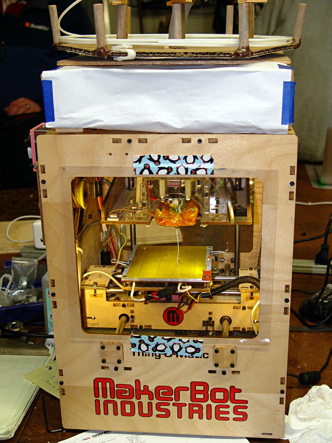
    The gutted TOM286 carcass with the MBI hardware off to the side:

    TOM286 - gutted electronics bay
    TOM286 – gutted electronics bay

    After a few sessions, it looked pretty cheerful again:

    TOM286 - reborn at Squidwrench
    TOM286 – reborn at Squidwrench

    The penguin duct tape adds a festive flair, don’t you agree?

    This is what you see when looking down through the acrylic baseplate:

    Azteeg X3 - inside TOM286
    Azteeg X3 – inside TOM286

    The blurry silver rectangle off to the left is an aluminum channel glommed to bottom of the acrylic baseplate with silicone snot to eliminate a nasty mechanical resonance.

    The thermal cutout circuitry isn’t wired in yet; the ATX power supply has its -Power-On pin hotwired to the adjacent ground pin for now. The X3 gets its power directly from the +12 V supply, so there doesn’t seem to be any way to power the X3 from the +5 V Standby ouput, deliver +12 V to the motors, and switch the supply through the X3’s ATX output pin.

    The heaters work fine, the motors turn properly, and the extruder feeds molten plastic; all the motor calibrations seem to be pretty close. The first test object was a total botch, of course, but the printer’s parts seem to work OK again.

    Next step: calibration!

  • Sherline Tommy Bar Handles

    While putting the speed wrenches in the box with the Sherline four-jaw chuck, it occurred to me that I had all the makings of a handle for Sherline’s steel tommy bars:

    Sherline Tommy Bar Handle - solid model
    Sherline Tommy Bar Handle – solid model

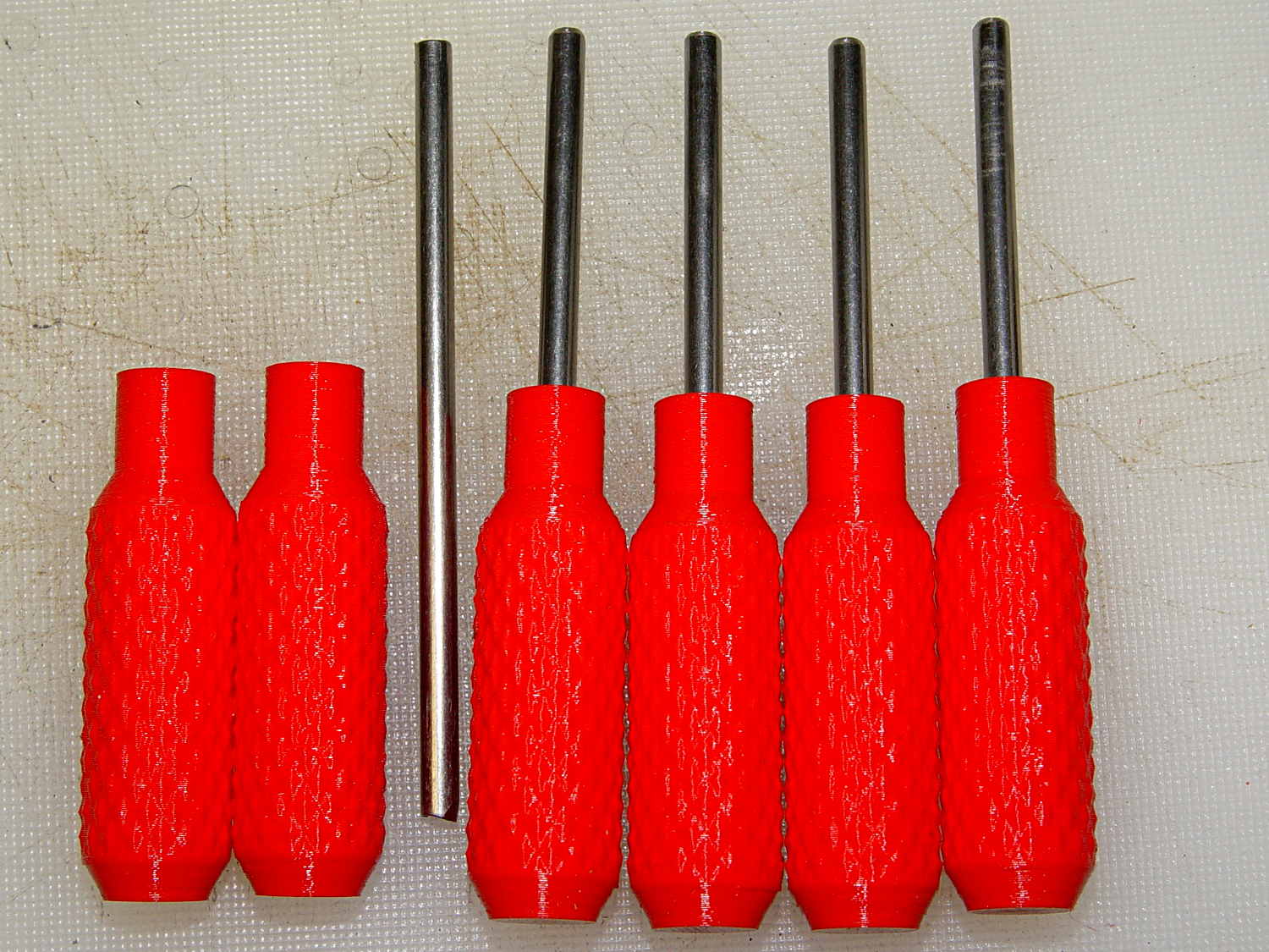
    Because these are intended for pushing, rather than twisting, I dialed the knurl back to 32 DP, reduced the depth to 0.5 mm, and ran the bar almost all the way through the handle for strength:

    Sherline Tommy Bar Handles
    Sherline Tommy Bar Handles

    A dab of urethane adhesive inside the handle holds the bar in place. They started out a snug slip fit, so we’ll see how well that holds the bars in place.

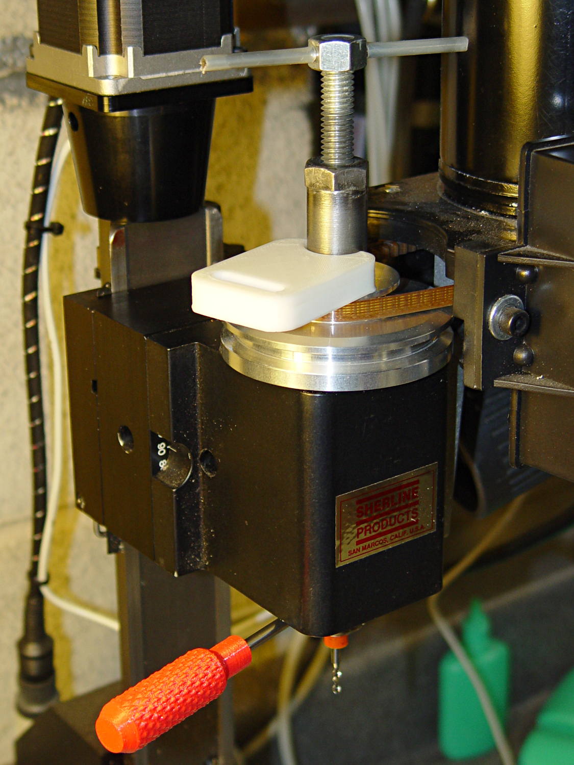
    A tommy bar holds the spindle against the torque from the collet pusher:

    Sherline CNC mill - tommy bar and collet pusher
    Sherline CNC mill – tommy bar and collet pusher

    A pair will come in handy with the three-jaw chuck the next time that one appears.

    The white slab is a very early 3D printed tool from my Thing-O-Matic, made to hold the pin at exactly the proper distance from the pulley so it fits squarely into the pusher and locks it to the spindle:

    Locking pin holder - spindle end view
    Locking pin holder – spindle end view

    Other folks make much nicer tommy bar handles than mine, but I’d say my 3D printed handles beat a common nail any day!

    The OpenSCAD source code:

    // Knurled handles for Sherline tommy bars
    // Ed Nisley - KE4ZNU - December 2013
    
    use <knurledFinishLib_v2.scad>
    
    //- Extrusion parameters must match reality!
    //  Print with 2 shells and 3 solid layers
    
    ThreadThick = 0.20;
    ThreadWidth = 0.40;
    
    HoleWindage = 0.2;			// extra clearance
    
    Protrusion = 0.1;			// make holes end cleanly
    
    PI = 3.14159265358979;
    inch = 25.4;
    
    //----------------------
    // Dimensions
    
    ShaftDia = 10.0;				// un-knurled section diameter
    ShaftLength = 10.0;				//  ... length
    
    SocketDia = 4.0;				// tommy bar diameter
    SocketDepth = 40.0;
    
    KnurlLen = 35.0;				// length of knurled section
    KnurlDia = 15.0;				//   ... diameter
    KnurlDPNom = 32;				// Nominal diametral pitch = (# diamonds) / (OD inches)
    
    DiamondDepth = 0.5;				//   ... depth of diamonds
    DiamondAspect = 2;				// length to width ratio
    
    NumDiamonds = floor(KnurlDPNom * KnurlDia / inch);
    echo(str("Num diamonds: ",NumDiamonds));
    
    NumSides = 4*(NumDiamonds - 1);		// 4 facets per diamond. Library computes diamonds separately!
    
    KnurlDP = NumDiamonds / (KnurlDia / inch);				// actual DP
    echo(str("DP Nom: ",KnurlDPNom," actual: ",KnurlDP));
    
    DiamondWidth = (KnurlDia * PI) / NumDiamonds;
    
    DiamondLenNom = DiamondAspect * DiamondWidth;					// nominal diamond length
    DiamondLength = KnurlLen / round(KnurlLen/DiamondLenNom);		//  ... actual
    
    TaperLength = 0.75*DiamondLength;
    
    //----------------------
    // Useful routines
    
    module PolyCyl(Dia,Height,ForceSides=0) {			// based on nophead's polyholes
    
      Sides = (ForceSides != 0) ? ForceSides : (ceil(Dia) + 2);
    
      FixDia = Dia / cos(180/Sides);
    
      cylinder(r=(FixDia + HoleWindage)/2,
               h=Height,
               $fn=Sides);
    }
    
    module ShowPegGrid(Space = 10.0,Size = 1.0) {
    
      Range = floor(50 / Space);
    
    	for (x=[-Range:Range])
    	  for (y=[-Range:Range])
    		translate([x*Space,y*Space,Size/2])
    		  %cube(Size,center=true);
    }
    
    //- Build it
    
    ShowPegGrid();
    
    difference() {
    	union() {
    		render(convexity=10)
    		translate([0,0,TaperLength])
    			knurl(k_cyl_hg=KnurlLen,
    				  k_cyl_od=KnurlDia,
    				  knurl_wd=DiamondWidth,
    				  knurl_hg=DiamondLength,
    				  knurl_dp=DiamondDepth,
    				  e_smooth=DiamondLength/2);
    		color("Orange")
    		cylinder(r1=ShaftDia/2,
    					r2=(KnurlDia - DiamondDepth)/2,
    					h=(TaperLength + Protrusion),
    					$fn=NumSides);
    		color("Orange")
    		translate([0,0,(TaperLength + KnurlLen - Protrusion)])
    			cylinder(r2=ShaftDia/2,
    					r1=(KnurlDia - DiamondDepth)/2,
    					h=(TaperLength + Protrusion),
    					$fn=NumSides);
    		color("Moccasin")
    		translate([0,0,(2*TaperLength + KnurlLen - Protrusion)])
    			cylinder(r=ShaftDia/2,h=(ShaftLength + Protrusion),$fn=NumSides);
    
    	}
    	translate([0,0,(2*TaperLength + KnurlLen + ShaftLength - SocketDepth + Protrusion)])
    		PolyCyl(SocketDia,(SocketDepth + Protrusion),6);
    }
    
  • 3D Printed Bike Helmet Mirror Mount: Two Years Later

    A bit over two years ago, I hoped my design for a bike helmet mirror mount would prove to be more durable than the fragile commercial mirrors I’d given up on:

    Helmet mirror mount - 3D model - Fit layout
    Helmet mirror mount – 3D model – Fit layout

    Having just tightened the teeny screws that hold the joints in place for the first time since I glued it to the helmet, I’d say it’s working fine. The 2-56 elevation setscrew has worn a slight dent in the arc and the 3-48 azimuth screw worked slightly loose; the mirror didn’t fall apart, but the position wasn’t as stable as it should be.

    If I ever re-do the design, I’ll try adding a recessed metal (brass?) strip along the top of that arc, as that’s the most finicky adjustment. Perhaps a shoe under the setscrew would be better?

    Two years of road grit show up clearly against the yellow plastic, though:

    Bike helmet mirror mount - two years
    Bike helmet mirror mount – two years

    For the record, those 2-56 setscrews require 35 mil hex keys; as Eks reminds me, any design requiring those screws is just crazy talk.

  • Practical Solid Modeling for 3D Printing with OpenSCAD

    I’m teaching an introduction to OpenSCAD for Squidwrench this evening in Highland NY…

    To quote from the course description:

    This intensive course will bootstrap you into designing solid models of useful objects suitable for production on a 3D printer.

    We won’t build anything like this, but it makes a nice showpiece:

    Solid Model - Oblique Exploded Top
    Solid Model – Oblique Exploded Top

    The presentation in PDF form: Practical Solid Modeling for 3D Printing with OpenSCAD – 2013-09-25

    I plan on a bunch of learning-by-doing, but, in the event the typing becomes burdensome, here are the OpenSCAD files:

    A simplified version of the Dishwasher Rack Protector, minus the support structure:

    Dishwasher rack protector - support model
    Dishwasher rack protector – support model
    // Dishwasher rack protector
    // Simplified version for OpenSCAD course
    // Ed Nisley KE4ZNU - July 2013
    
    ThreadThick = 0.25;
    ThreadWidth = 0.40;
    
    Protrusion = 0.1;							// make holes end cleanly
    
    //-------
    // Dimensions
    
    PinDia = 4.0 + 0.5;                 // upright pin diameter + clearance
    PinRadius = PinDia/2;
    
    PinOC = 3.4;                        // bar center to pin center
    
    PinTubeLength = 15.0;               // length of upright tube along pin
    
    BarDia = 4.7 + 0.2;                 // horizontal bar diameter + clearance
    BarRadius = BarDia/2;
    
    BarTubeLength = 30.0;               // length of horizontal half tube along bar
    
    TubeWall = 4*ThreadWidth;           // wall thickness -- allow for fill motion
    
    TubeSides = 4 * 4;                  // default side count for tubes (in quadrants)
    $fn = TubeSides;
    
    SupportClear = 0.85;                // support structure clearance fraction
    
    //-------
    
    module ShowPegGrid(Space = 10.0,Size = 1.0) {
    
      Range = floor(50 / Space);
      for (x=[-Range:Range])
        for (y=[-Range:Range])
          translate([x*Space,y*Space,Size/2])
            %cube(Size,center=true);
    }
    
    //-------
    // Put it together
    
    module Protector() {
    
      difference() {
        union() {
          translate([0,PinOC,0])
            rotate(180/TubeSides)
              cylinder(r=(PinDia + 2*TubeWall)/2,h=PinTubeLength);
          translate([-BarTubeLength/2,0,0])
            rotate([0,90,0])
              rotate(180/TubeSides)
                cylinder(r=(BarDia + 2*TubeWall)/2,h=BarTubeLength);
        }
    
        translate([0,PinOC,-Protrusion])
          rotate(180/TubeSides)
            cylinder(r=PinRadius,h=(PinTubeLength + 2*Protrusion),$fn=TubeSides);
    
        translate([-BarTubeLength/2,0,0])
          rotate([0,90,0])
            rotate(180/TubeSides)
              translate([0,0,-Protrusion])
                cylinder(r=BarRadius,h=(BarTubeLength + 2*Protrusion));
    
        translate([0,0,-(BarRadius + TubeWall + Protrusion)/2])
          cube([(BarTubeLength + 2*Protrusion),
              BarTubeLength,
              (BarRadius + TubeWall + Protrusion)],center=true);
      }
    
    }
    
    //-------
    // Build it!
    
    ShowPegGrid();
    
    Protector();
    

    And a bare-bones version:

    // Dishwasher rack protector
    // Trivial version for OpenSCAD course
    // Ed Nisley KE4ZNU - July 2013
    
    	difference() {
    		union() {
    			translate([0,3.4,0])
    				color("lightgreen")
    					cylinder(r=5,h=15);
    			translate([-15.0,0,0])
    				rotate([0,90,0])
    					color("lightyellow")
    						cylinder(r=6.0,h=30.0);
    		}
    
    		translate([0,3.4,-15.0])
    			cylinder(r=3.0,h=3*15.0);
    
    		translate([-30.0,0,0])
    			rotate([0,90,0])
    				cylinder(r=3.0,h=2*30.0);
    
    		translate([0,0,-5.0])
    			cube([50,50,10.0],center=true);
    	}
    

    A simplified version of the Sink Drain Strainer I wrote up for Digital Machinist:

    3D Printed Sink Strainer - overview
    3D Printed Sink Strainer – overview
    // Strainer Plate
    // Simplified version for OpenSCAD course
    // Ed Nisley KE4ZNU - July 2013
    
    Layout = "Build";				// Handle Plate Show Build
    
    Protrusion = 0.1;							// make holes end cleanly
    
    PlateOD = 150.0;							// strainer plate diameter
    PlateThick = 5.0;							//  .. thickness
    
    HoleOD = 6.0;								// hole diameter
    
    NumRings = 4;								// number of hole rings
    RingMinDia = 20.0;							// innermost ring diameter
    RingStep = 30.0;							// ring diameter increment
    
    HandleOD = 8.0;								// handle diameter
    HandleLength = 15.0;						//  .. length
    HandlePegOD = HandleOD/2;					//  .. mounting peg
    HandlePegLength = 1.5;
    
    //-- Create single handle
    
    module Handle() {
    
    	cylinder(r=HandleOD/2,h=HandleLength);
    	cylinder(r=HandlePegOD/2,h=(HandleLength + HandlePegLength));
    
    }//-- Create single ring of holes
    
    module RingHoles(RingDia,HoleDia,Thickness) {
    
    	Num = floor(90/asin(HoleDia/RingDia));	// how many holes fit in ring?
    	echo(str("Dia: ",RingDia," Holes: ",Num));
    
    	for(n=[0:(Num-1)]) {
    		rotate([0,0,n*360/Num])
    		translate([RingDia/2,0,-Protrusion])
    			cylinder(r=HoleDia/2,
    					h=(Thickness + 2*Protrusion));
    	}
    
    }
    
    //-- Create strainer plate with holes
    
    module StrainerPlate() {
    
    	difference() {
    		cylinder(r=PlateOD/2,h=PlateThick);
    		for (RingID = [0:NumRings-1]) {
    			RingHoles((RingMinDia + RingID*RingStep),
    						HoleOD,PlateThick);
    		}
    		cylinder(r=HandlePegOD/2,h=3*PlateThick,center=true);
    	}
    }
    
    //-- Build it!
    
    if (Layout == "Plate")
    	StrainerPlate();
    
    if (Layout == "Handle")
    	Handle();
    
    if (Layout == "Build") {
    	StrainerPlate();
    	translate([PlateOD/2,PlateOD/2,0])
    		Handle();
    	translate([(PlateOD/2 - 2*HandleOD),
    				PlateOD/2,0])
    		Handle();
    	}
    
    if (Layout == "Show") {
    	color("LightYellow")
    		StrainerPlate();
    	color("LightGreen") {
    		translate([0,0,-HandleLength])
    			Handle();
    		translate([0,0,(PlateThick + HandleLength)])
    			rotate([180,0,0])
    			Handle();
    	}
    
    }
    

    And a bare-bones version, minus the handles:

    Protrusion = 0.1;
    
    PlateOD = 150.0;
    PlateThick = 5.0;
    HoleOD = 6.0;
    
    NumRings = 4;
    RingMinDia = 20.0;
    RingStep = 30.0;
    
    module RingHoles(RingDia,HoleDia,Thickness) {
    
      Num = floor(90/asin(HoleDia/RingDia));
      echo("Dia: ",RingDia," holes: ",Num);
    
      for(n=[0:(Num-1)]) {
    			rotate([0,0,n*360/Num])
    	 	 translate([RingDia/2,0,-Protrusion])
    			  cylinder(r=HoleDia/2,
    														h=(Thickness + 2*Protrusion));
      }
    }
    
    difference() {
    	cylinder(r=PlateOD/2,h=PlateThick);
    	for (RingID = [0:NumRings-1]) {
    		RingHoles((RingMinDia + RingID*RingStep),
    					       HoleOD,PlateThick);
    	}
    }
    

    [Update: The talk went well and took a bit under three hours, although by mutual agreement we didn’t fire up the M2 at the end. I’ll work on a short talk about Design for Printability and we’ll run that with a separate printing session. A good time was had by all!]

  • Creating a Curvelicious Cookie Cutter

    So, for reasons I need not go into, I needed an OpenSCAD solid model of a custom cookie cutter produced on an Afinia 3D printer from a Trimble Sketchup model:

    Afinia Robot Cutter - on raft
    Afinia Robot Cutter – on raft

    The cutter is still attached to the raft that, it seems, is required for passable results on the Afinia’s platform.

    Having already figured out how to wrap a cutter around a shape, the most straightforward procedure starts by extracting the cutter’s shape. So, lay the cutter face down on the scanner and pull an image into GIMP:

    Afinia Robot - scan
    Afinia Robot – scan

    Blow out the contrast to eliminate the background clutter, then posterize to eliminate shadings:

    Afinia Robot - scan enhanced
    Afinia Robot – scan enhanced

    Select the black interior region, grow the selection by a pixel or two, then shrink it back to eliminate (most of) the edge granularity, plunk it into a new image, and fill with black:

    Afinia Robot - scan filled
    Afinia Robot – scan filled

    Now the magic happens…

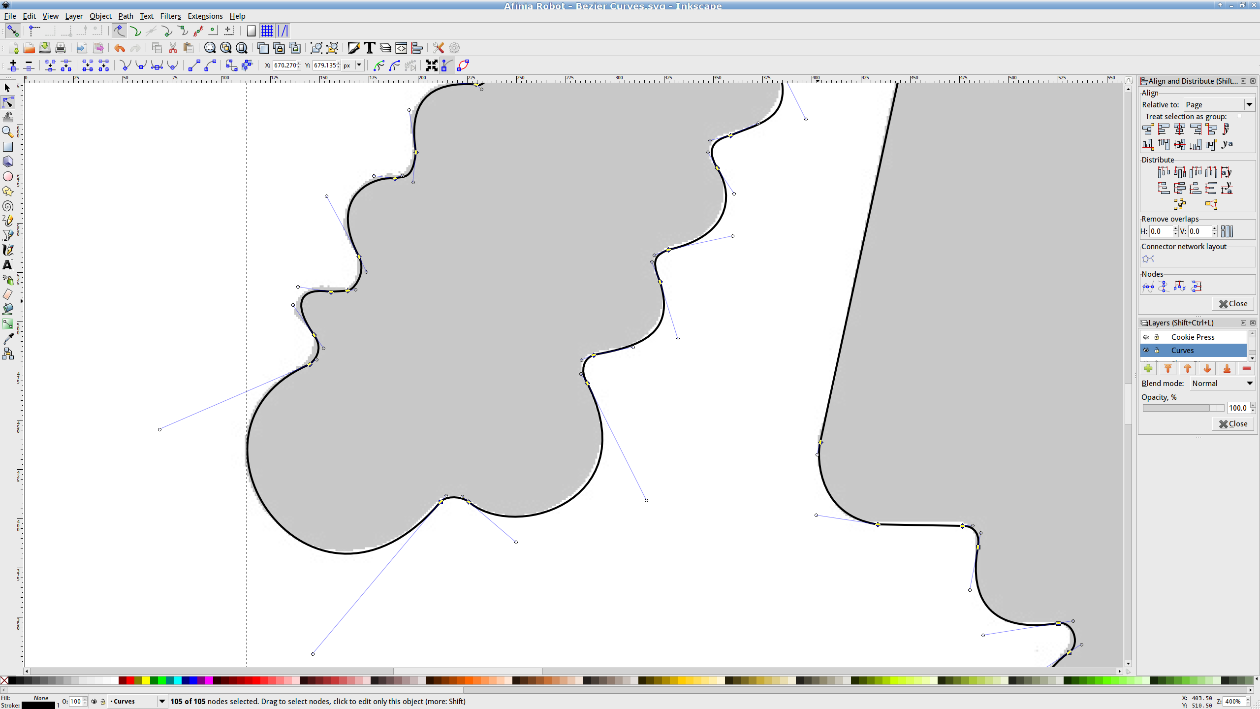
    Import the bitmap image into Inkscape. In principle, you can auto-trace the bitmap outline and clean it up manually, but a few iterations of that convinced me that it wasn’t worth the effort. Instead, I used Inkscape’s Bézier Curve tool to drop nodes (a.k.a. control points) at all the inflection points around the image, then warped the curves to match the outline:

    Afinia Robot - Bezier spline fitting
    Afinia Robot – Bezier spline fitting

    If you’re doing that by hand, you could start with the original scanned image, but the auto-trace function works best with a high-contrast image and, after you give up on auto-tracing, you’ll find it’s easier to hand-trace a high-contrast image.

    Anyhow, the end result of all that is a smooth path around the outline of the shape, without all the gritty details of the pixelated version. Save it as an Inkscape SVG file for later reference.

    OpenSCAD can import a painfully limited subset of DXF files that, it seems, the most recent versions of Inkscape cannot produce (that formerly helpful tutorial being long out of date). Instead, I exported (using “Save as”) the path from Inkscape to an Encapsulated Postscript file (this is a PNG, as WordPress doesn’t show EPS files):

    Afinia Robot - Bezier Curves.eps
    Afinia Robot – Bezier Curves.eps

    It’s not clear what the EPS file contains; I think it’s just a list of points around the path that doesn’t include the smooth Bézier goodness. That may account for the grittiness of the next step, wherein the pstoedit utility converts the EPS file into a usable DXF file:

    pstoedit dxf:-polyaslines Afinia\ Robot\ -\ Bezier\ Curves.eps Afinia\ Robot\ -\ outline.dxf
    

    Unfortunately, either the EPS file doesn’t have enough points on each curve or pstoedit automatically sets the number of points and doesn’t provide an override: contrary to what you (well, I) might think, the -splineprecision option doesn’t apply to whatever is in the EPS file. In any event, the resulting DXF file has rather low-res curves, but they were good enough for my purposes and OpenSCAD inhaled the DXF and emitted a suitable STL file:

    Afinia Robot - shape slab
    Afinia Robot – shape slab

    To do that, you set the Layout variable to “Slab”, compile the model, and export the STL.

    Being interested only in the process and its results, not actually cutting and baking cookies, I tweaked the OpenSCAD parameters to produce stumpy “cutters”:

    Afinia Robot - solid model
    Afinia Robot – solid model

    You do that by setting the Layout variable to “Build”, compile the model, and export yet another STL. In the past, this seemed to be a less fragile route than directly importing and converting the DXF at each stage, but that may not be relevant these days. In any event, having an STL model of the cookie may be useful in other contexts, so it’s not entirely wasted effort.

    Run the STL through Slic3r to get the G-Code as usual.

    The resulting model printed in about 20 minutes apiece on the M2:

    Robot Cutter - stumpy version
    Robot Cutter – stumpy version

    As it turns out, the fact that the M2 can produce ready-to-use cutters, minus the raft, is a strong selling point.

    Given a workable model, the next step was to figure out the smallest possible two-thread-wide cutter blade, then run variations of the Extrusion Factor to see how that affected surface finish. More on that in a while.

    The OpenSCAD source isn’t much changed from the original Tux Cutter; the DXF import required different scale factors:

    // Robot cookie cutter using Minkowski sum
    // Ed Nisley KE4ZNU - Sept 2011
    // August 2013 adapted from the Tux Cutter
    
    Layout = "Build";				// Build Slab
    
    //- Extrusion parameters - must match reality!
    
    ThreadThick = 0.25;
    ThreadWidth = 0.40;
    
    function IntegerMultiple(Size,Unit) = Unit * ceil(Size / Unit);
    
    MaxSize = 150;				// larger than any possible dimension ...
    
    Protrusion = 0.1;
    
    //- Cookie cutter parameters
    
    Size = 95;
    
    TipHeight = IntegerMultiple(3.0,ThreadThick);
    TipThick = 1.5*ThreadWidth;			// 1.5* = thinnest 2-thread wall, 1.0* thread has gaps
    
    WallHeight = IntegerMultiple(1.0,ThreadThick);
    WallThick = 4.5*ThreadWidth;
    
    LipHeight = IntegerMultiple(1.0,ThreadWidth);
    LipThick = IntegerMultiple(5,ThreadWidth);
    
    //- Wrapper for the shape of your choice
    
    module Shape(Size) {
      Robot(Size);
    }
    
    //- A solid slab of Tux goodness in simple STL format
    // Choose magic values to:
    //		center it in XY
    //		reversed across Y axis (prints with handle on bottom)
    //		bottom on Z=0
    //		make it MaxSize from head to feet
    
    module Tux(Scale) {
      STLscale = 250;
      scale(Scale/STLscale)
    	translate([105,-145,0])
    	  scale([-1,1,24])
    		import(
    		  file = "/mnt/bulkdata/Project Files/Thing-O-Matic/Tux Cookie Cutter/Tux Plate.stl",
    		  convexity=5);
    }
    
    module Robot(Scale) {
        STLscale = 100.0;
        scale(Scale / STLscale)
    			scale([-1,1,10])
    				import("/mnt/bulkdata/Project Files/Thing-O-Matic/Pinkie/M2 Challenge/Afinia Robot.stl",
    					convexity=10);
    }
    
    //- Given a Shape(), return enlarged slab of given thickness
    
    module EnlargeSlab(Scale, WallThick, SlabThick) {
    
    	intersection() {
    	  translate([0,0,SlabThick/2])
    		cube([MaxSize,MaxSize,SlabThick],center=true);
    	  minkowski(convexity=5) {
    		Shape(Scale);
    		cylinder(r=WallThick,h=MaxSize,$fn=16);
    	  }
    	}
    
    }
    
    //- Put peg grid on build surface
    
    module ShowPegGrid(Space = 10.0,Size = 1.0) {
    
      RangeX = floor(100 / Space);
      RangeY = floor(125 / Space);
    
    	for (x=[-RangeX:RangeX])
    	  for (y=[-RangeY:RangeY])
    		translate([x*Space,y*Space,Size/2])
    		  %cube(Size,center=true);
    
    }
    
    //- Build it
    
    ShowPegGrid();
    
    if (Layout == "Slab")
    	Shape(Size);
    
    if (Layout == "Build")
    	difference() {
    	union() {
    		translate([0,0,(WallHeight + LipHeight - Protrusion)])
    		EnlargeSlab(Size,TipThick,TipHeight + Protrusion);
    		translate([0,0,(LipHeight - Protrusion)])
    		EnlargeSlab(Size,WallThick,(WallHeight + Protrusion));
    		EnlargeSlab(Size,LipThick,LipHeight);
    	}
    	Shape(Size);					// punch out cookie hole
    	}
    
  • Makergear M2: Mechanical Setup

    That Slic3r configuration presumes a somewhat nonstandard mechanical setup for my M2…

    I put the XY coordinate origin in the middle of the platform, so that laying objects out for printing doesn’t require knowing how large the platform will be: as long as the printer is Big Enough, you (well, I) can print without further attention.

    The RepRap world puts the XY coordinate origin in the front left corner of the platform, so that the platform size sets the maximum printable coordinates and all printing happens in Quadrant I.  This has the (major, to some folks) advantage of using only positive coordinates, while requiring an offset for each different platform.

    Yes, depending on which printer software you use, you can (automagically) center objects on your platform; this is often the only way to find objects created with Trimble (formerly Google) Sketchup. I am a huge fan of knowing exactly what’s going to happen before the printing starts, so I position my solid models exactly where I want them, right from the start. For example, this OpenSCAD model of the bike helmet mirror parts laid out for printing:

    Helmet mirror mount - 3D model - Show layout
    Helmet mirror mount – 3D model – Show layout

    … exactly matches the plastic on the Thing-O-Matic’s platform, with the XY origin right down the middle of the platform:

    Helmet mirror mount on build platform - smaller mirror shaft
    Helmet mirror mount on build platform – smaller mirror shaft

    It’d print exactly the same, albeit with more space around the edges, on the M2’s platform.

    Similarly, the Z axis origin sits exactly on the surface of the platform. That way, the Z axis coordinate equals the actual height of the current thread extrusion in a measurable way: when you set the Z axis to, say, 2.0 mm, you can measure that exact distance between the extruder nozzle and the platform:

    Taper gauge below nozzle
    Taper gauge below nozzle

    Now, admittedly, I fine-tune that distance by measuring the height of the skirt thread around the printed object, but the principle remains: a thread printed  on the platform with Z=0.25 should be exactly 0.25 mm thick.

    The start.gcode file handles all that:

    ;-- Slic3r Start G-Code for M2 starts --
    ;  Ed Nisley KE4NZU - 15 April 2013
    M140 S[first_layer_bed_temperature]	; start bed heating
    G90				; absolute coordinates
    G21				; millimeters
    M83				; relative extrusion distance
    M84				; disable stepper current
    G4 S3			; allow Z stage to freefall to the floor
    G28 X0			; home X
    G92 X-95			; set origin to 0 = center of plate
    G1 X0 F30000		; origin = clear clamps on Y
    G28 Y0			; home Y
    G92 Y-127 		; set origin to 0 = center of plate
    G1 Y-125 F30000	; set up for prime at front edge
    G28 Z0			; home Z
    G92 Z1.0			; set origin to measured z offset
    M190 S[first_layer_bed_temperature]	; wait for bed to finish heating
    M109 S[first_layer_temperature]	; set extruder temperature and wait
    G1 Z0.0 F2000		; plug extruder on plate
    G1 E10 F300		; prime to get pressure
    G1 Z5 F2000		; rise above blob
    G1 X5 Y-122 F30000	; move away from blob
    G1 Z0.0 F2000		; dab nozzle to remove outer snot
    G4 P1			; pause to clear
    G1 Z0.5 F2000		; clear bed for travel
    ;-- Slic3r Start G-Code ends --
    

    The wipe sequence, down near the bottom, positions the extruder at the front center edge of the glass plate, waits for it to reach the extrusion temperature, then extrudes 10 mm of filament to build up pressure behind the nozzle. The blob generally hangs over the edge of the platform and usually doesn’t follow the nozzle during the next short move and dab to clear the mess:

    M2 - Wipe blobs on glass platform
    M2 – Wipe blobs on glass platform

    I’ve also configured Slic3r to extrude at least 25 mm of filament in at least three passes around the object. After that, the extruder pressure has stabilized and the first layer of the object begins properly.

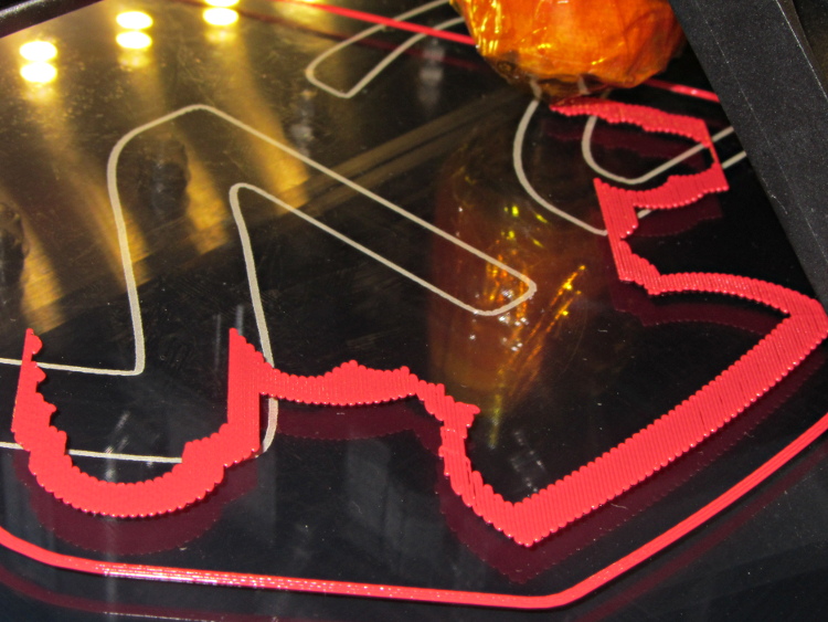
    Which brings up another difference: the first layer printed on the platform is exactly like all the others. It’s not smooshed to get better adhesion or overfilled to make the threads stick together:

    Robot cookie cutter - printing first layer
    Robot cookie cutter – printing first layer

    I print the first layer at 25 mm/s to give the plastic time to bond to the platform and use hairspray to make PLA stick to glass like it’s glued down.

    After that, it’s just ordinary 3D printing…