The Smell of Molten Projects in the Morning

Ed Nisley's Blog: Shop notes, electronics, firmware, machinery, 3D printing, laser cuttery, and curiosities. Contents: 100% human thinking, 0% AI slop.

Tag: Sherline

Sherline CNC mill

  • Tube Turning Adapters

    Tube Turning Adapters

    Finishing the PVC tubes reinforcing the vacuum cleaner adapters required fixtures on each end:

    Dirt Devil adapter - pipe turning
    Dirt Devil adapter – pipe turning

    Because the tubes get epoxied into the adapters, there’s no particular need for a smooth surface finish and, in fact, some surface roughness makes for a good epoxy bond. The interior of a 3D printed adapter is nothing if not rough; the epoxy in between will be perfectly happy.

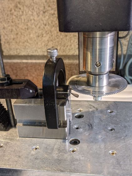
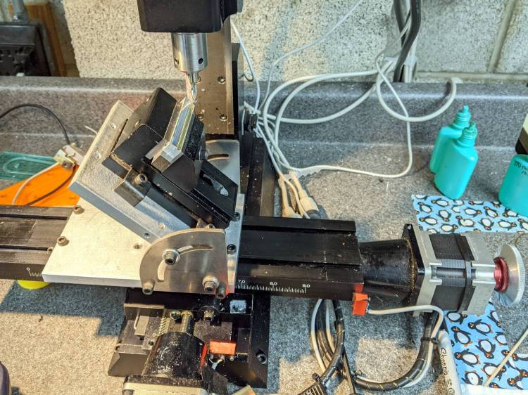
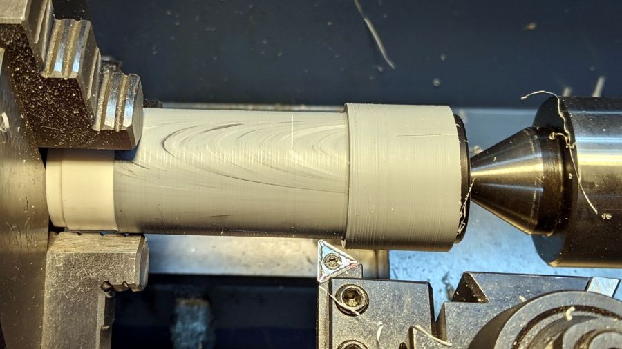
    Turning the tubes started by just grabbing the conduit in the chuck and peeling the end that stuck out down to the finished diameter, because the conduit was thick-walled enough to let that work.

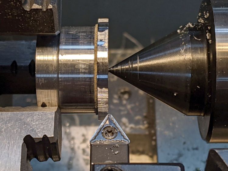
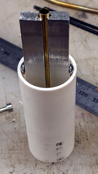
    The remaining wall was so thin that the chuck would crunch it into a three-lobed shape, so the white ring in the chuck is a scrap of PVC pipe turned to fit the tube ID and provide enough reinforcement to keep the tube round.

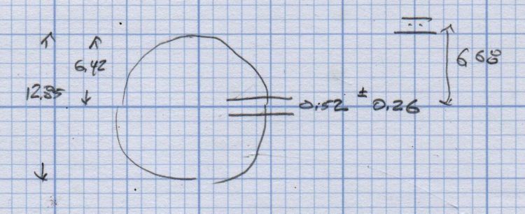
    The conduit ID isn’t a controlled dimension and was, in point of fact, not particularly round. It was, however, smooth, which counts for more than anything inside a tube carrying airborne fuzzy debris; polishing the interior of a lathe-bored pipe simply wasn’t going to happen.

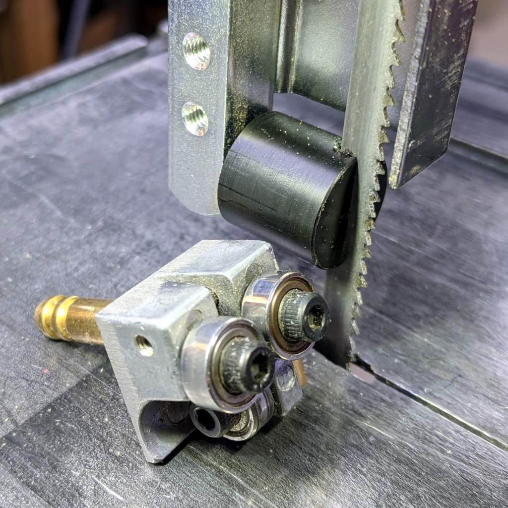
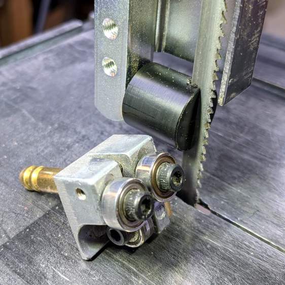
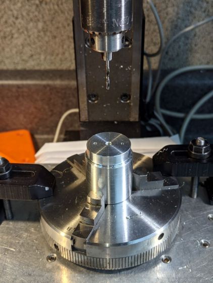
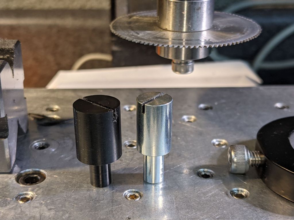
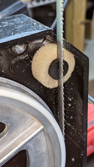
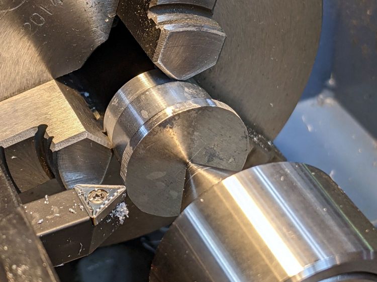
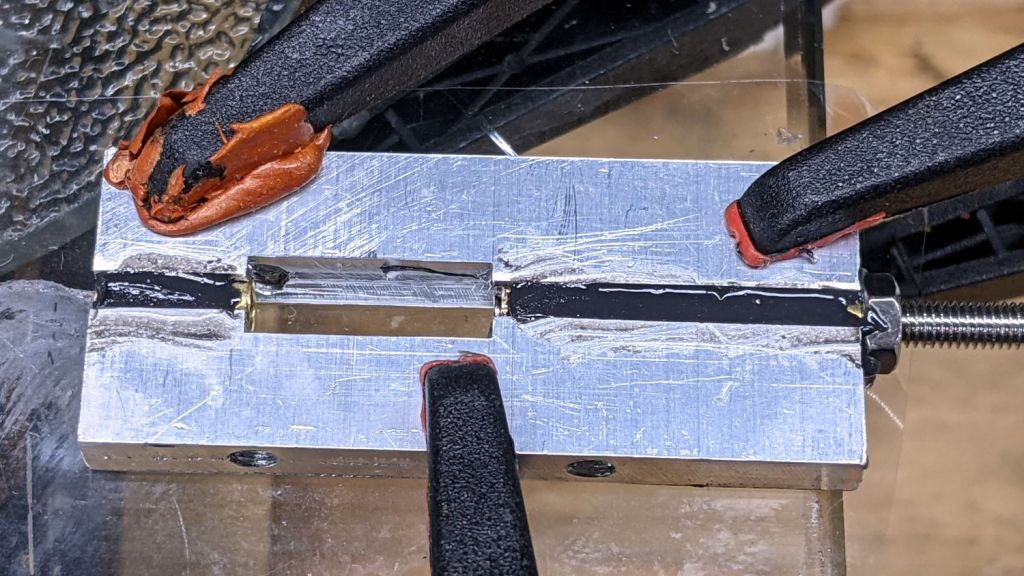
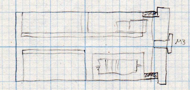
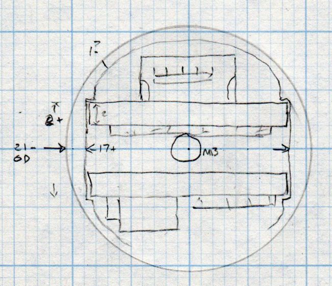
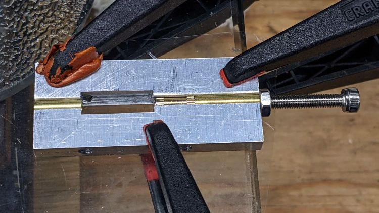
    The fixture on the other end started as a scrap of polycarbonate bandsawed into a disk with a hole center-drilled in the middle:

    Pipe end lathe fixture - center drilling
    Pipe end lathe fixture – center drilling

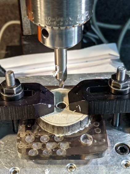
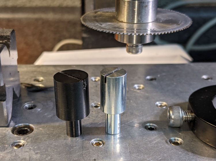
    Stick it onto a disk turning fixture and sissy-cut the OD down a little smaller than the eventual tube OD:

    Pipe end lathe fixture - turning OD
    Pipe end lathe fixture – turning OD

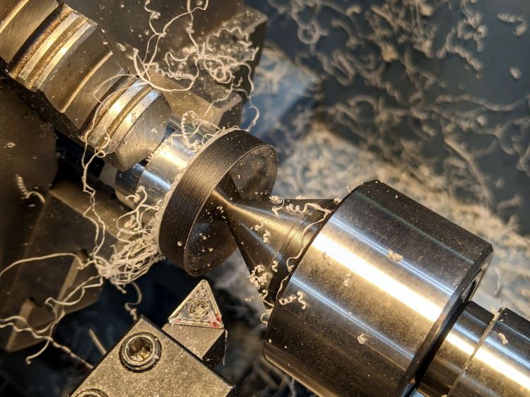
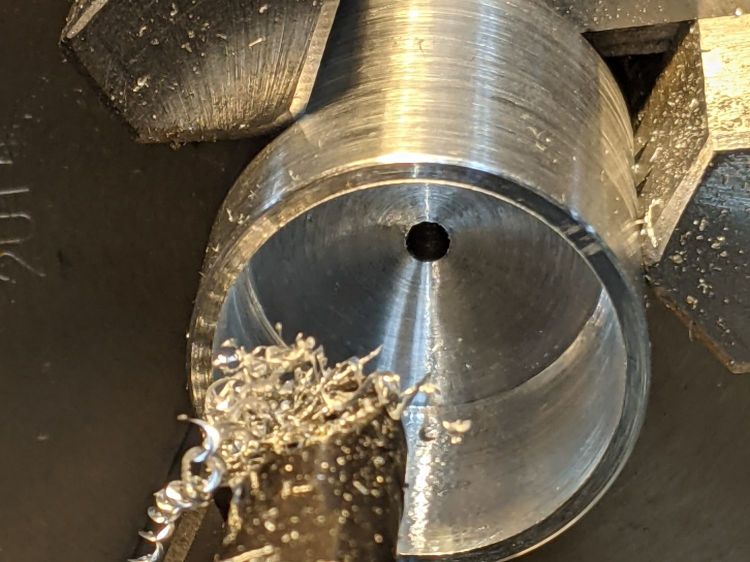
    Turn the end down to fit the tube ID, flip it around to center-drill the other side, stick it into the tube, and finally finish the job:

    Dirt Devil adapter - pipe fixture
    Dirt Devil adapter – pipe fixture

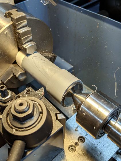
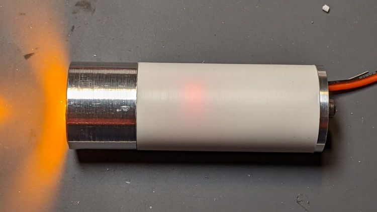
    The nice layering effect along the tube probably comes from molding the conduit from recycled PVC with no particular concern for color matching.

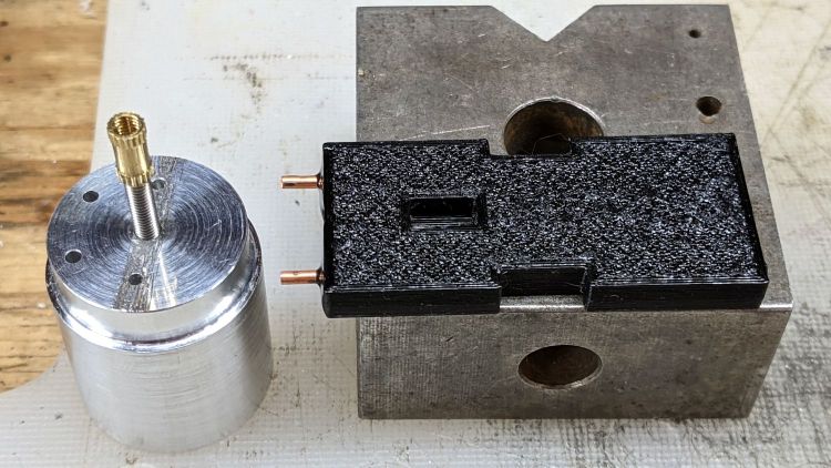
    A family portrait of the fixtures with a finished adapter:

    Dirt Devil adapter - fixtures
    Dirt Devil adapter – fixtures

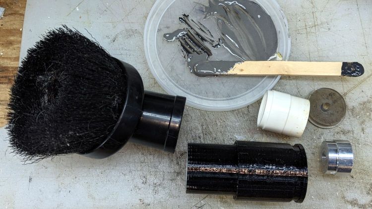
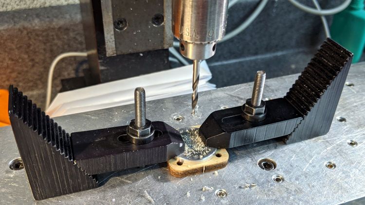
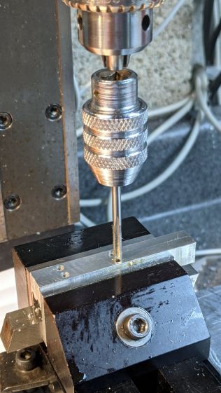
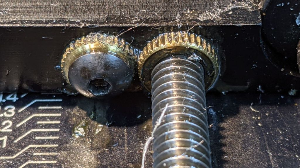
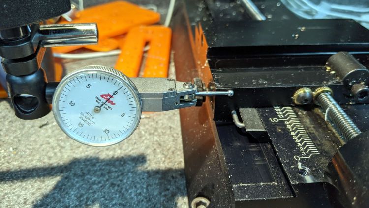
    A fine chunk of Quality Shop Time: solid modeling, 3D printing, mini-lathe turning, and even some coordinate drilling on the Sherline.

  • Micro-Mark Bandsaw: Acetal Upper Blade Guide

    Micro-Mark Bandsaw: Acetal Upper Blade Guide

    There being nothing like a good new problem to take one’s mind off all one’s old problems:

    Micro-Mark Bandsaw - acetal upper blade guide installed
    Micro-Mark Bandsaw – acetal upper blade guide installed

    It’s basically the same as the lower blade guide, except coming from a stick of 5/8 inch acetal. A scant 6 mm stem goes into the vertical square rod, with a flat matching the setscrew coming up from the bottom to hold it in proper alignment.

    I came within a heartbeat of cutting the slot parallel to the flat.

    It worked OK while cutting a chunk of stout aluminum tube: so far, so good!

    The impressive chunk of hardware is the OEM blade guide, with the brass tube for coolant flow all over the bearings. It’s mostly intended for use with the diamond blade, so I’ll swap it back in when I finally get around to cutting some slate for base plates.

  • Tour Easy Rear Running Light: LED Heatsink

    Tour Easy Rear Running Light: LED Heatsink

    Because the rear running light will have a higher duty cycle than the front light, I made the (admittedly too small) heatsink slightly longer, with a deeper recess to protect the lens from cargo on the rear rack:

    Tour Easy Rear Running Light - boring LED recess
    Tour Easy Rear Running Light – boring LED recess

    Boring that nice flat bottom is tedious; I must lay in a stock of aluminum tubing to simplify the process.

    Drilling the holes went smoothly:

    Tour Easy Rear Running Light - drilling LED heatsink
    Tour Easy Rear Running Light – drilling LED heatsink

    Those two holes fit a pair of pins aligning the circuit plate, with a screw and brass insert holding it to the heatsink. Scuffing a strip across the aluminum might give the urethane adhesive (you can see uncured globs on the pins) a better grip:

    Tour Easy Rear Running Light - circuit plate attachment
    Tour Easy Rear Running Light – circuit plate attachment

    The screw / insert /pins are glued into the plate to permanently bond it to the heatsink. The screw occupies only half of the insert, with the longer screw from the end cap pulling the whole affair together.

    The two holes on the left pass both LED leads to one side of the circuit plate, where they connect to the current regulator and its sense resistor.

  • Micro-Mark Bandsaw: Acetal Blade Guide

    Micro-Mark Bandsaw: Acetal Blade Guide

    The Micro-Mark bandsaw has a metal blade guide below the table that contributes to the awful noise it makes while running, even when it’s not cutting anything. Having recently touched the Delrin = acetal rod stash, a simple project came to mind.

    A doodle with the original metal guide dimensions:

    Micro-Mark Bandsaw - metal blade guide dimensions
    Micro-Mark Bandsaw – metal blade guide dimensions

    The 10 mm dimension is non-critical, so I started with a 1/2 inch acetal rod and turned the stub end to match.

    A doodle suggested how to carve the slot with a 20.5 mil = 0.52 mm slitting saw, with the offset from a Z touchoff at the top:

    Micro-Mark Bandsaw - acetal blade guide - slitting doodles
    Micro-Mark Bandsaw – acetal blade guide – slitting doodles

    The V block setup required swapping out the overly long OEM screw for a shorter 5 mm SHCS to clear the Sherline’s motor:

    Micro-Mark Bandsaw - acetal guide slitting
    Micro-Mark Bandsaw – acetal guide slitting

    The end result looked pretty good:

    Micro-Mark Bandsaw - acetal vs steel blade guides
    Micro-Mark Bandsaw – acetal vs steel blade guides

    And it looks like it pretty much belongs in the saw:

    Micro-Mark Bandsaw - acetal blade guide installed
    Micro-Mark Bandsaw – acetal blade guide installed

    The 6 mm stud goes into a hole in the frame, where a setscrew holds it in place. You must remove the blade to extract / replace the guide, with the correct position having the end of the slot just touching the back of the blade.

    The foam ring apparently keeps crud away from the stud on the backside; I doubt it’s mission-critical.

    The saw became somewhat quieter; the ball bearing guides above the table now generate most of the racket. At some point I’ll try replacing them with a block, probably made from UHMW, with a simple slit to guide the blade.

    Plastic guides may not last as long as the steel ones, but occasional replacements will be worth it if the saw runs quieter.

  • Tour Easy 1 W Amber Running Light: End Cap

    Tour Easy 1 W Amber Running Light: End Cap

    My initial doodles suggested an end cap with an opening for the Arduino’s USB port and something for the power cable from the Bafang controller:

    1 W LED Running Light - internal assembly
    1 W LED Running Light – internal assembly

    Common sense finally broke out and I made a simple disk cover held in place with an M3 screw:

    1 W Amber Running Light - bench test
    1 W Amber Running Light – bench test

    Unfortunately, I cut the PVC shell flush with the USB port, which meant the cap couldn’t have a little shoulder to stabilize it on the shell. Maybe next time?

    Machining the disk required using the scrap of aluminum rod left over from the heatsink as a fixture with a piece of sandpaper stuck to the front surface:

    1 W Amber Running Light - end cap setup
    1 W Amber Running Light – end cap setup

    The live center presses the bandsawed + disk sanded cap against the sandpaper, providing barely enough traction for sissy cuts reducing the disk to the proper diameter:

    1 W Amber Running Light - end cap turning
    1 W Amber Running Light – end cap turning

    It actually worked pretty well, although next time I’ll skip the sandpaper, affix the disk directly to the double sided duct tape, and be done with it.

    Line up the center punch dimple and drill a hole for the M3 screw:

    1 W Amber Running Light - end cap drilling
    1 W Amber Running Light – end cap drilling

    The power cable port turned into a little slot bandsawed into the edge of the disk with the sharp edges filed off.

    Basically, the thing needs some road testing before I build one for real …

  • Tour Easy 1 W Amber Running Light: Internal Plate

    Tour Easy 1 W Amber Running Light: Internal Plate

    A semi-scaled doodle laying out an Arduino Nano and the MP1584 regulator board suggested they might fit behind the heatsink with the 1 W LED:

    Amber running light - board layout doodle - side
    Amber running light – board layout doodle – side

    A somewhat more detailed doodle of the end view prompted me to bore the PVC pipe out to 23 mm:

    Amber running light - board layout doodle - end
    Amber running light – board layout doodle – end

    The prospect of designing a 3D printed holder for the boards suggested Quality Shop Time combined with double-stick foam tape would ensure a better outcome.

    So I bandsawed the remains of a chunky angle bracket into a pair of rectangles, flycut All The Sides to square them up, and tapped a pair of M3 holes along one edge of each:

    1 W LED Running Light - baseplate tapping
    1 W LED Running Light – baseplate tapping

    The other long edges got the V groove that killed the Sherline’s Y axis nut:

    Sherline Y-Axis Nut Mishap - setup
    Sherline Y-Axis Nut Mishap – setup

    The groove holds a length of 4 mm OD (actually 5/32 inch, but don’t tell anybody) brass tubing:

    1 W LED Running Light - baseplate trial fit
    1 W LED Running Light – baseplate trial fit

    The M3 button head screws are an admission of defeat, as I could see no way of controlling the width + thickness of the aluminum slabs to get a firm push fit in the PVC tube. The screws let me tune for best picture after everything else settled out.

    A little more machining opened up the top of the groove:

    1 W LED Running Light - baseplate dry assembly
    1 W LED Running Light – baseplate dry assembly

    A short M3 button head screw (with its head turned down to 4 mm) drops into the slot and holds the slab to the threaded hole in the LED heatsink. The long screw is holding the threaded insert in place for this dry fit.

    I doodled a single long screw through the whole thing, but having it fall off the heatsink when taking the rear cover off seemed like a Bad Idea™. An M3 button head screw uses a 2 mm hex key that fits neatly through the threaded insert, thereby making it work.

    Butter it up with epoxy, scrape off the excess, and let things cure:

    1 W LED Running Light - baseplate curing
    1 W LED Running Light – baseplate curing

    This was obviously made up as I went along …

  • Sherline CNC Mill: Y-Axis Nut Mishap

    Sherline CNC Mill: Y-Axis Nut Mishap

    The need to gnaw a V groove into the side of two 60 mm aluminum bars led to this Sherline CNC mill setup:

    Sherline Y-Axis Nut Mishap - setup
    Sherline Y-Axis Nut Mishap – setup

    Milling the near end of the bars put the angle plate’s rear lock screw within a millimeter of the column; the vise fits in exactly one spot on the angle plate and that’s where the jaws must be.

    While controlling the mill with the Joggy Thing and some manual command entry, because it’s easier than real CNC programming, I overshot the near end and rammed the column with enough enthusiasm to dislodge the Y-axis leadscrew nut. An interlude of utter confusion ended with the backlash preload nut firmly jammed against the leadscrew coupler on the other end of travel:

    Sherline Y-Axis Nut Mishap - stuck preload nut
    Sherline Y-Axis Nut Mishap – stuck preload nut

    The paper shreds show where the bellows formerly stuck on the Y axis stage.

    The backlash nut chewed off a few star lock gear teeth on its way out, as seen here just above where they mesh:

    Sherline Y-Axis Nut Mishap - chewed star nut
    Sherline Y-Axis Nut Mishap – chewed star nut

    It’s been quite a few years since I took the thing apart to replace the nuts, so I used the opportunity to lube the otherwise inacessible X axis leadscrew inside its table upside down on the bench.

    The setscrew locking the Y axis leadscrew nut in place heaves into view with the X axis table off:

    Sherline Y-Axis Nut Mishap - setscrew
    Sherline Y-Axis Nut Mishap – setscrew

    I thought about jamming it in place with a second 10-32 setscrew, but the ones on hand were just an itsy too long and collided with the X-axis table:

    Sherline Y-Axis Nut Mishap - doubled setscrew
    Sherline Y-Axis Nut Mishap – doubled setscrew

    The thought of having the additional setscrew work loose, grind into the underside of the table, and require major surgery for recovery persuaded me to drop it back in the drawer.

    With everything in place, I adjusted the backlash (on both axes) down to a few mils:

    Sherline Y-Axis Nut Mishap - backlash test
    Sherline Y-Axis Nut Mishap – backlash test

    Tweaking the X axis preload nut under the table is not my idea of a good time, but it’s been quite a while since I had to do that.

    Folding the new paper bellows and installing them took about as long as repairing the mill.

    Milling the second V groove worked fine; all is right with the Sherline again.