The Smell of Molten Projects in the Morning

Ed Nisley's Blog: Shop notes, electronics, firmware, machinery, 3D printing, laser cuttery, and curiosities. Contents: 100% human thinking, 0% AI slop.

Tag: Sherline

Sherline CNC mill

  • Tour Easy Running Light: Heatsink Machining

    Tour Easy Running Light: Heatsink Machining

    Having acquired some thick-wall (1 inch OD, ¾ inch ID) aluminum tube, making the LED heatsink and lens holder for a running light generates a lot less scrap. A new doodle gives the dimensions in a rather Picasso-ish layout:

    Running Light - dimension doodles
    Running Light – dimension doodles

    The back end of the tube gets turned down to 23 mm OD and cleaned up to 19 mm ID, then scored to give the epoxy something to grip:

    Front Running Light - Heatsink shell scoring
    Front Running Light – Heatsink shell scoring

    The front end gets bored to 22.5 mm for the lens holder and has its OD cleaned up to 25 mm:

    Front Running Light - finished shell
    Front Running Light – finished shell

    Clean up the end of a ¾ inch rod to 19 mm OD, knurl it a little to increase the OD ever so slightly and improve its griptivity, slice off a bit more than 10 mm, butter it up with JB Weld epoxy, and shove it into the shell with its front end aligned and its back end sticking out:

    Front Running Light - epoxied plug in shell - rear
    Front Running Light – epoxied plug in shell – rear

    Face off the back end and the front end looks fine as assembled:

    Front Running Light - epoxied plug in shell - front
    Front Running Light – epoxied plug in shell – front

    Grab it in the Sherline mill’s three jaw chuck to:

    • Drill & tap the M3 central hole for the stud holding the circuit plate to the back end
    • Drill 1.6 mm blind holes for the circuit plate pins
    • Drill 2 mm through holes for the LED wires, 60° apart

    Which looks like this from the front:

    Front Running Light - drilled heatsink - front
    Front Running Light – drilled heatsink – front

    And like this with the circuit plate screwed & glued to the rear:

    Front Running Light - circuit plate mounted
    Front Running Light – circuit plate mounted

    Clean up the OD of some ¾ inch PVC pipe to 25 mm, bore it out to 23 mm.

    While the Sherline is set up, drill a pair of 2 mm holes in the lens holder for the wires, aligned so they’ll match the heatsink holes.

    Because we live in the future, laser-cut the rear cap from some edge-lit acrylic with a black inner disk:

    Front Running Light - PVC tube - end cap
    Front Running Light – PVC tube – end cap

    Cutting that cap with the notch included is now trivially easy, compared to the previous machining.

    Now for some circuitry …

  • World War II Dog Tag Layout

    World War II Dog Tag Layout

    Quite some time ago, I hammered out G-Code to engrave ersatz dog tags for a Cabin Fever demo:

    Cabin Fever Dog Tag
    Cabin Fever Dog Tag

    A dozen years later, making a World War II dog tag is a whole lot easier:

    John Q Public - WWII dog tag
    John Q Public – WWII dog tag

    Well, “easier” if you allow laser engraving in white-on-black Trolase using a font intended to mimic a typewriter.

    Close enough, methinks.

    Which comes from a simple layout:

    John Q Public - WWII dog tag - LB layout
    John Q Public – WWII dog tag – LB layout

    The outline traces a scanned image of my father’s tag, fitting a few hand-laid splines around the curves:

    John Q Public - WWII dog tag - spline curves
    John Q Public – WWII dog tag – spline curves

    I generated a random serial number based on my father’s draftee status (he was in his early 30s during his South Sea Island tour) and state of residence; my apologies to anyone carrying it for real. His blood type was A and (I think) the religion code marks him as “Brethren”, a common group in my ancestry.

    Given the outline, various plastics, and a laser, other effects become possible:

    WWII dog tag outline test
    WWII dog tag outline test

    It might come in handy for something, someday.

    The LightBurn SVG layout as GitHub Gist:

  • Tailor’s Clapper: CNC Pocketing

    Tailor’s Clapper: CNC Pocketing

    Separating the interior contour of the finger grip from its overall shape let me reduce the woodworking to a simple pocketing operation:

    Ironing Weight Finger Grip
    Ironing Weight Finger Grip

    Start by aligning the finished block to put the joint between the pieces parallel to the X axis, then touch off at the center:

    Ironing Weight - alignment
    Ironing Weight – alignment

    A pair of clamps screwed to the tooling plate act as fixtures to align the block when it’s flipped over to mill the other pocket.

    Just to see how it worked, I set up a GCMC program to produce a trochoidal milling pattern using the sample program:

    Tailors Clapper - Pocket Milling Path
    Tailors Clapper – Pocket Milling Path

    Now, most folks would say the Sherline lacks enough speed and stiffness for trochoidal milling:

    Ironing weight - trochoidal milling
    Ironing weight – trochoidal milling

    Aaaand I would agree with them: chugging along at 24 in/min = 600 mm/min doesn’t put the 10 k RPM spindle speed to good use. Fortunately, oak doesn’t require much in the way of machine stiffness and the trochoid path does ensure good chip clearance, so there’s that.

    If I had to do a lot of trochoid milling, I’d tweak the GCMC sample code to short-cut the return path across the circle diameter, rather than air-cut the last half of every circumference.

    The code starts by emptying a circular pocket so the trochoid path begins in clear air, rather than trenching into solid wood.

    Eventually it finishes the pocket:

    Ironing weight - grip pocket
    Ironing weight – grip pocket

    After the trochoid finishes, one climb-milling pass around the perimeter clears the little ripple between each trochoid orbit.

    Flip it over, clamp it down, touch off the middle, and do it all again.

    The next step is filling those pockets with a pair of comfy grips.

    The GCMC source code as a GitHub Gist:

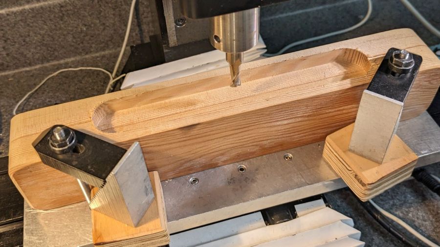
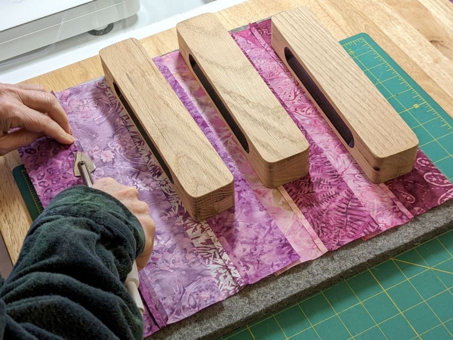
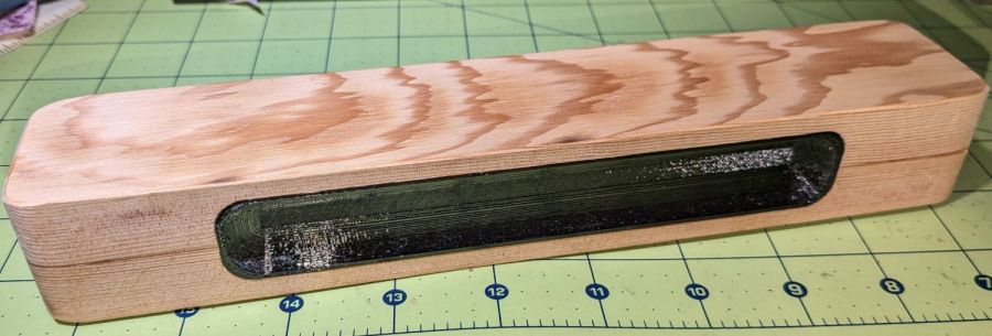
    // Ironing weight pocketing
    // Ed Nisley KE4ZNU – 2023-01
    //—–
    // Library routines
    include("/opt/gcmc/example/cc_hole.inc.gcmc");
    include("varcs.inc.gcmc");
    include("tracepath_comp.inc.gcmc");
    include("trochoidal.inc.gcmc");
    /*
    include("tracepath.inc.gcmc");
    include("engrave.inc.gcmc");
    */
    //—–
    // Useful constants
    SafeZ = 10.0mm; // above all obstructions
    TravelZ = 2.0mm; // within engraving / milling area
    BlockHome = [0.0mm,0.0mm,TravelZ]; // Origin on surface at center of pocket
    FALSE = 0;
    TRUE = !FALSE;
    //—–
    // Overall values
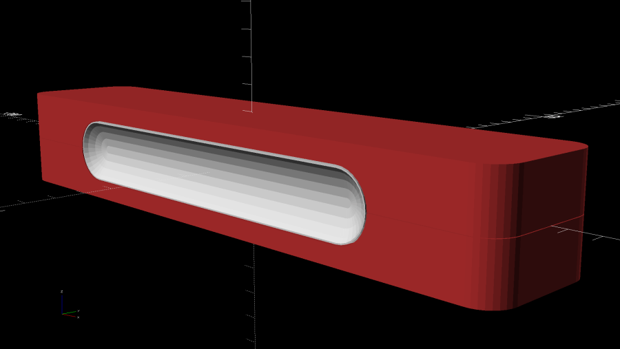
    Socket = [160.0mm,25.0mm,7.0mm]; // raw grip recess into block
    RoundEnds = TRUE; // TRUE for smooth rounded endcaps
    SocketRadius = RoundEnds ? Socket.y/2 : 10.0mm;
    comment("SocketRadius: ",SocketRadius);
    CutterDia = 6.32mm – 0.15; // actual cutter diameter – windage
    MillStep = 0.25 * CutterDia; // stepover in XY plane
    comment("CutterDia: ",CutterDia," MillStep: ",MillStep);
    MillClean = MillStep/2;
    PlungeSpeed = 150.0mm; // cutter Z plunge into work
    MillSpeed = 600.0mm; // XY speed
    if (CutterDia > SocketRadius) {
    error("Cutter too large for corner radius");
    }
    CornerOC = head(Socket,2) – 2*[SocketRadius,SocketRadius];
    comment("CornerOC: ",CornerOC);
    Corners = RoundEnds ? // rear left CCW around slot
    {-CornerOC/2, CornerOC/2} :
    {[-CornerOC.x,CornerOC.y]/2, [-CornerOC.x,-CornerOC.y]/2, [CornerOC.x,-CornerOC.y]/2, CornerOC/2};
    comment("Corners: ", Corners);
    if (RoundEnds) {
    SlotPerimeter = {[0.0mm,Socket.y/2,-Socket.z]}; // entry point at center rear
    SlotPerimeter += {Corners[0] + [0.0mm,SocketRadius]};
    SlotPerimeter += varc_ccw([-SocketRadius,-SocketRadius],SocketRadius) + SlotPerimeter[-1];
    SlotPerimeter += varc_ccw([+SocketRadius,-SocketRadius],SocketRadius) + (Corners[0] + [-SocketRadius,0.0mm]);
    SlotPerimeter += {Corners[1] + [0.0mm,-SocketRadius]}; // across front
    SlotPerimeter += varc_ccw([+SocketRadius,+SocketRadius],SocketRadius) + SlotPerimeter[-1];
    SlotPerimeter += varc_ccw([-SocketRadius,+SocketRadius],SocketRadius) + (Corners[1] + [+SocketRadius,0.0mm]);
    }
    else {
    SlotPerimeter = {[0.0mm,Socket.y/2,-Socket.z]}; // entry point at center rear
    SlotPerimeter += {Corners[0] + [0.0mm,SocketRadius]};
    SlotPerimeter += varc_ccw([-SocketRadius,-SocketRadius],SocketRadius) + SlotPerimeter[-1];
    SlotPerimeter += {Corners[1] + [-SocketRadius,0.0mm]};
    SlotPerimeter += varc_ccw([+SocketRadius,-SocketRadius],SocketRadius) + SlotPerimeter[-1];
    SlotPerimeter += {Corners[2] + [0.0mm,-SocketRadius]}; // across front
    SlotPerimeter += varc_ccw([SocketRadius,SocketRadius],SocketRadius) + SlotPerimeter[-1];
    SlotPerimeter += {Corners[3] + [SocketRadius,0.0mm]};
    SlotPerimeter += varc_ccw([-SocketRadius,SocketRadius],SocketRadius) + SlotPerimeter[-1];
    }
    //— Begin cutting
    goto([-,-,TravelZ]);
    goto(BlockHome);
    if (!RoundEnds) { // clear corners outward of main pocket
    foreach(Corners; xy) {
    comment("Plunge corner at: ",xy);
    feedrate(PlungeSpeed);
    goto(xy);
    move([-,-,-Socket.z]);
    comment(" pocket");
    feedrate(MillSpeed);
    cc_hole(xy,(SocketRadius – MillClean),CutterDia/2,MillStep,-Socket.z);
    goto([-,-,TravelZ]);
    comment(" done!");
    }
    }
    comment("Open slot");
    TrochRadius = (Socket.y – CutterDia)/2 – MillClean;
    TrochPath = {[-(Socket.x/2 – TrochRadius – CutterDia/2 – MillStep),TrochRadius],
    [ (Socket.x/2 – TrochRadius – CutterDia/2 – MillStep),TrochRadius]};
    comment(" clear landing zone");
    xy = [TrochPath[0].x,0.0mm];
    feedrate(PlungeSpeed);
    goto(xy);
    move([-,-,-Socket.z]);
    feedrate(MillSpeed);
    cc_hole(xy,Socket.y/2 – MillClean,CutterDia/2,MillStep,-Socket.z);
    goto([-,-,TravelZ]);
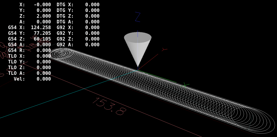
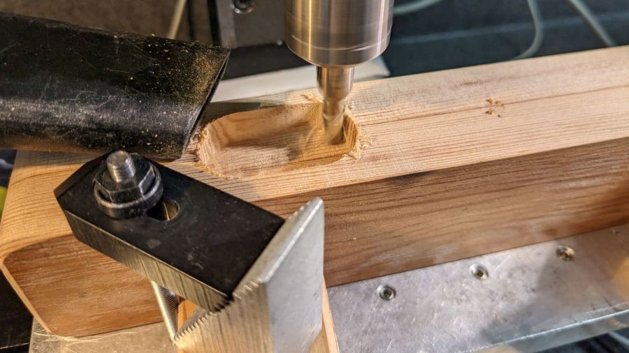
    comment(" trochoid pocket milling");
    feedrate(MillSpeed);
    trochoid_move(TrochPath[0],TrochPath[1],
    -Socket.z, TrochRadius, MillStep);
    goto([-,-,TravelZ]);
    comment("Clean slot perimeter");
    feedrate(MillSpeed);
    goto([-,-,-Socket.z]);
    tracepath_comp(SlotPerimeter,CutterDia/2,TPC_CLOSED + TPC_LEFT + TPC_ARCIN + TPC_ARCOUT);
    goto([-,-,TravelZ]);
    goto(BlockHome);
    #!/bin/bash
    # Ironing weight finger grip pocketing
    # Ed Nisley KE4ZNU – 2023-01
    Flags='-P 4 –pedantic' # quote to avoid leading hyphen gotcha
    # Set these to match your file layout
    LibPath='/opt/gcmc/library'
    Prolog='prolog.gcmc'
    Epilog='epilog.gcmc'
    #—–
    gcmc $Flags \
    –include "$LibPath" –prologue "$Prolog" –epilogue "$Epilog" \
    "Ironing weight grip pocket.gcmc" > "Grip pocket.ngc"
    view raw pocket.sh hosted with ❤ by GitHub
  • Ironing Weight, a.k.a. Tailor’s Clapper: Overview

    Ironing Weight, a.k.a. Tailor’s Clapper: Overview

    Mary wanted some ironing weights, formally known as tailor’s clappers, to produce flatter seams as she pieced fabric together:

    Ironing weight - flattened seam
    Ironing weight – flattened seam

    The weights are blocks of dense, hard, unfinished wood:

    Ironing weight - seam ironing A
    Ironing weight – seam ironing A

    One can buy commercial versions ranging from cheap Amazon blocks to exotic handmade creations, but a comfortable grip on a block sized to Mary’s hands were important. My lack of woodworking equipment constrained the project, but the picture shows what we settled on.

    The general idea is a rounded wood block with 3D printed grips:

    Ironing Weight Finger Grip
    Ironing Weight Finger Grip

    All other clappers seem to have a simple slot routed along the long sides, presumably using a round-end or ball cutter, which means the cutter determines the shape. This being the age of rapid prototyping, I decided to put the complex geometry in an easy-to-make printed part inserted into a simple CNC-milled pocket.

    The first pass at the grip models:

    Ironing Weight Finger Grip - slicer preview
    Ironing Weight Finger Grip – slicer preview

    Both recesses came from spheres sunk to their equators with their XY radii scaled appropriately, then hulled into the final shape. Customer feedback quickly reported uncomfortably abrupt edges along the top and bottom:

    Ironing Weight - maple prototype
    Ironing Weight – maple prototype

    We also decided the straight-end design didn’t really matter, so all subsequent grips have rounded ends to simplify milling the pocket into the block.

    With the goal in mind, the next few posts will describe the various pieces required to make a nice tailor’s clapper customized to fit the user’s hand.

  • CO₂ Laser Cutter: Improved PIN-10D Photodiode Filter Holder

    CO₂ Laser Cutter: Improved PIN-10D Photodiode Filter Holder

    Anything would be better than just taping some gel filters to the front of the bare photodiode package:

    Laser output - photodiode kludge
    Laser output – photodiode kludge

    Right?

    I heaved the slab of ½ inch black acrylic left over from the Totally Featureless (WWVB) Clock into the laser cutter and, two passes at 90% power later, had a somewhat lumpy 32 mm donut with an 11 mm hole in the middle. Because acrylic is opaque to the IR light from a CO₂ laser (which is why it cuts so well) and black acrylic is opaque to visible light (which is what the photodiode is designed for), this is at least as good as an aluminum housing and much easier to make.

    Chuck the donut into Tiny Lathe and bore out the hole:

    PIN-10D photodiode filter holder - boring ID
    PIN-10D photodiode filter holder – boring ID

    When it’s a snug fit to ½ inch brass tube (about the same size as the photodiode’s active area), flip it around, and bore the other size out to fit the photodiode case.

    Ram the tube in place, grab the large recess, and center the tube:

    PIN-10D photodiode filter holder - centering snout
    PIN-10D photodiode filter holder – centering snout

    That’s the chuck-in-chuck trick I used with the coasters, because the neither of the larger four-jaw chucks close far enough to get their inside jaws inside those little holes.

    [Edit: Got that backwards: I bored the big recess first.]

    Skim most of the OD down, then, because I am a dolt forgot to put a spacer in there, flip it around again, get it running true (the chuck aligns the flat side):

    PIN-10D photodiode filter holder - turning OD
    PIN-10D photodiode filter holder – turning OD

    Then skim the rest of the OD to clean it up.

    Cut some filter gels to fit inside the recess:

    PIN-10D photodiode filter holder - filter disc cutting
    PIN-10D photodiode filter holder – filter disc cutting

    Even though they’re pretty much transparent to thermal IR, a focused IR laser beam cuts them just fine. The little tab at 6 o’clock (remember round clocks with hands?) keeps the cut circle from falling out.

    Drill & tap for an M3 setscrew to hold the photodiode in place:

    PIN-10D photodiode filter holder - parts
    PIN-10D photodiode filter holder – parts

    Put them all together:

    PIN-10D photodiode filter holder - assembled
    PIN-10D photodiode filter holder – assembled

    I must conjure a better mount for the thing, because this is way too precarious:

    PIN-10D photodiode filter holder - test install
    PIN-10D photodiode filter holder – test install

    Early results suggest it works better than the previous hack job, without ambient light sneaking around the edges of the filter pack.

  • Laser Cutter: Improving the Red-Dot Pointer

    Laser Cutter: Improving the Red-Dot Pointer

    The red-dot pointer on the OMTech laser cutter has the same problem as my laser aligner for the Sherline mill: too much brightness creating too large a visual spot. In addition, there’s no way to make fine positioning adjustments, because the whole mechanical assembly is just a pivot.

    The first pass involved sticking a polarizing filter on the existing mount while I considered the problem:

    OMTech red dot pointer - polarizing filter installed
    OMTech red dot pointer – polarizing filter installed

    The red dot pointer module is 8 mm OD and the ring is 10 mm ID, but you will be unsurprised to know the laser arrived with the module jammed in the mount with a simple screw. Shortly thereafter, I turned the white Delrin bushing on the lathe to stabilize the pointer and installed a proper setscrew, but it’s obviously impossible to make delicate adjustments with that setup.

    Making the polarizing filter involves cutting three circles:

    OMTech red dot pointer - polarizing filter
    OMTech red dot pointer – polarizing filter

    Rotating the laser module in the bushing verified that I could reduce the red dot to a mere shadow of its former self, but it was no easier to align.

    Replacing the Delrin bushing with a 3D printed adjuster gets closer to the goal:

    Pointer fine adjuster - solid model
    Pointer fine adjuster – solid model

    Shoving a polarizing filter disk to the bottom of the recess, rotating the laser module for least brightness, then jamming the module in place produces a low-brightness laser spot.

    The 8 mm recess for the laser module is tilted 2.5° with respect to the Y axis, so (in principle) rotating the adjuster + module (using the wide grip ring) will move the red dot in a circle:

    Improved red-dot pointer - overview
    Improved red-dot pointer – overview

    The dot sits about 100 mm away at the main laser focal point, so the circle will be about 10 mm in diameter. In practice, the whole affair is so sloppy you get what you get, but at least it’s more easily adjusted.

    The M4 bolt clamping the holder to the main laser tube now goes through a Delrin bushing. I drilled out the original 4 mm screw hole to 6 mm to provide room for the bushing:

    Improved red-dot pointer - drilling bolt hole
    Improved red-dot pointer – drilling bolt hole

    The bushing has a wide flange to soak up the excess space in the clamp ring:

    Improved red-dot pointer - turning clamp bushing
    Improved red-dot pointer – turning clamp bushing

    With all that in place, the dimmer dot is visually about 0.3 mm in diameter:

    Improved red-dot pointer - offset
    Improved red-dot pointer – offset

    The crappy image quality comes from excessive digital zoom. The visible dot on the MDF surface is slightly larger than the blown-out white area in the image.

    The CO₂ laser hole is offset from the red laser spot by about 0.3 mm in both X and Y. Eyeballometrically, the hole falls within the (dimmed) spot diameter, so this is as good as it gets. I have no idea how durable the alignment will be, but it feels sturdier than it started.

    Because the red dot beam is 25° off vertical, every millimeter of vertical misalignment (due to non-flat surfaces, warping, whatever) shifts the red dot position half a millimeter in the XY plane. You can get a beam combiner to collimate the red dot with the main beam axis, but putting more optical elements in the beam path seems like a Bad Idea™ in general.

    The OpenSCAD source code as a GitHub Gist:

    // Laser cutter red-dot module fine adjust
    // Ed Nisley KE4ZNU 2022-09-22
    Layout = "Show"; // [Build, Show]
    /* [Hidden] */
    ThreadThick = 0.25;
    ThreadWidth = 0.40;
    HoleWindage = 0.2;
    Protrusion = 0.1; // make holes end cleanly
    inch = 25.4;
    ID = 0;
    OD = 1;
    LENGTH = 2;
    function IntegerMultiple(Size,Unit) = Unit * ceil(Size / Unit);
    //———————-
    // Dimensions
    PointerOD = 8.0 + 0.2; // plus loose turning fit
    Aperture = 5.0; // clear space for lens
    SkewAngle = 2.5;
    MountRing = [10.0,16.0,8.0]; // OEM laser module holder
    GripRim = [Aperture,MountRing[OD] + 2*1.5,3.0]; // finger grip around OD
    NumSides = 24;
    //———————-
    // Useful routines
    module PolyCyl(Dia,Height,ForceSides=0) { // based on nophead's polyholes
    Sides = (ForceSides != 0) ? ForceSides : (ceil(Dia) + 2);
    FixDia = Dia / cos(180/Sides);
    cylinder(r=(FixDia + HoleWindage)/2,
    h=Height,
    $fn=Sides);
    }
    //———————-
    // Holder geometry
    module Holder() {
    difference() {
    union() {
    cylinder(d=GripRim[OD],h=GripRim[LENGTH],$fn=NumSides);
    PolyCyl(MountRing[ID],MountRing[LENGTH] + GripRim[LENGTH],NumSides);
    }
    translate([0,0,-Protrusion]) // close enough without skew angle
    PolyCyl(Aperture,2*MountRing[LENGTH],NumSides);
    translate([0,0,MountRing[LENGTH]/2 + GripRim[LENGTH]])
    rotate([0,SkewAngle,0])
    translate([0,0,-MountRing[LENGTH]/2])
    PolyCyl(PointerOD,2*MountRing[LENGTH],NumSides);
    }
    }
    //———————-
    // Build it
    if (Layout == "Show") {
    Holder();
    }
    if (Layout == "Build") {
    Holder();
    }
  • Acrylic Coasters: Edge Finishing, Round 4

    Acrylic Coasters: Edge Finishing, Round 4

    Lacking a 4-jaw chuck for the lathe, this should suffice:

    Coaster Epoxy Rim - chuck-in-chuck setup
    Coaster Epoxy Rim – chuck-in-chuck setup

    Which is just the Sherline 4-jaw chuck chucked in the lathe’s 3-jaw chuck, with both chuck Jaw 1 positions lined up and marked on the acrylic disk fixture. The picture is a recreation set up after the fact, because I lack a good picture of the overall scene.

    Now it’s easy enough to center the fixture, stick the coaster in place with reasonable accuracy, then tweak the Sherline chuck to center the coaster:

    Coaster Epoxy Rim - turning setup
    Coaster Epoxy Rim – turning setup

    Because the bottom layer is a laser-cut disk, eyeballometrically aligning its edge to a simple pointer worked surprisingly well:

    Coaster Epoxy Rim - locating mirror edge
    Coaster Epoxy Rim – locating mirror edge

    Turning the OD down to match the bottom disk meant I could finally get decent results with zero drama:

    Coaster Epoxy Rim - turned samples
    Coaster Epoxy Rim – turned samples

    From the bottom, this one has a 3 mm mirror, the 3 mm fluorescent green frame + petals, and a 1.6 mm top sheet:

    Coaster Epoxy Rim - turned 6 petal mirror
    Coaster Epoxy Rim – turned 6 petal mirror

    This one has a 3M double-sided tape with low-surface-energy adhesive layers between the mirror and the fluorescent blue frame + petal, with epoxy between the top layer and the frame.

    Coaster Epoxy Rim - turned 4 petal
    Coaster Epoxy Rim – turned 4 petal

    If I never tell anybody, they’ll think the slightly granular look of the tape was deliberate; it looks OK to me.

    And, for completeness, the crash test dummy from the start of this adventure:

    Coaster Epoxy Rim - turned 6 petal black
    Coaster Epoxy Rim – turned 6 petal black

    I don’t know how to avoid the bubbles, as the usual torch-the-top and pull-a-vacuum techniques pop bubbles at the epoxy-air interface. These bubbles are trapped under the top acrylic sheet, even though I was rather painstaking about easing the layer down from one side to the other while chasing bubbles along.

    Maybe I can define bubbles as Part of the Art?

    Definitely fancier than chipboard, although not nearly as absorbent.