Ed Nisley's Blog: Shop notes, electronics, firmware, machinery, 3D printing, laser cuttery, and curiosities. Contents: 100% human thinking, 0% AI slop.
Two of the external Li-Ion battery packs I’m using with the bike radios seemed to fail quickly after being charged, so I sawed them open to check the state of the cells. This time I used the fine-tooth cutoff blades, rather than a coarse slitting saw:
Li-Ion pack – sawing case
As before, a 2 mm depth-of-cut, done 0.25 mm per pass after the first millimeter, seems about right. I didn’t saw the front of the case near the jack, which proved to be a mistake; the interlocked case halves need cutting.
No cell trouble found, which leads me to suspect an intermittent short in the battery-to-radio cable that trips the battery protection circuit. The spare cables went into hiding during the shop cleanout, so I can’t swap in a known-good cable just yet; of course, the existing cable behaves perfectly on the bench. The suspect cable is now on my bike and, if the problem follows the cable, further surgery will be in order.
A chunk of 1/2 inch = 12.7 mm brass hex rod looks pretty good as an ersatz heatsink serving as an ersatz plate cap on a halogen bulb standing in for a vacuum tube:
Halogen bulb brass cap – overview
The knockoff Neopixels measure just over 10 mm at their widest points, but some judicious filing rounded it off and brought it down to fit in the 3/8 inch = 0.375 = 9.52 mm hole I drilled in the hex:
Halogen bulb brass cap – wiring
I let it run for a day like that to make sure the thing wasn’t going to crap out, then epoxied everything in place. If the WS2812B controller fails, the repair will require drilling out all the electronics and wiring, then rebuilding it in place.
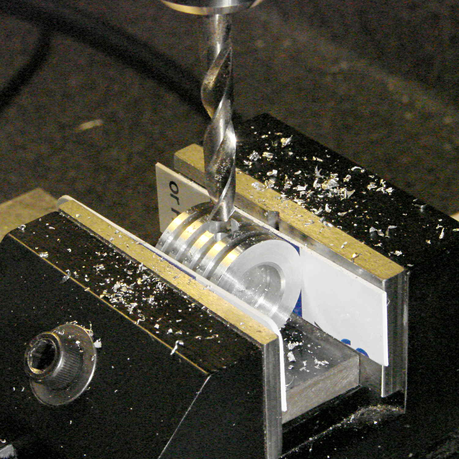
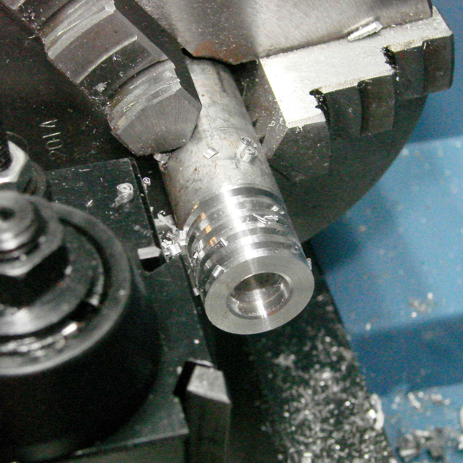
The fins come from the same HSS cutoff tool I used for the Bowl o’ Fire cap, cut at 2.5 mm intervals to produce 0.9 mm fins that IMO better suit the smaller diameter. I stopped cutting when the tool got through the hex flats to produce a continuous ring, cut the hex off a bit above the top fin, rounded the end with a carbide insert cutting tool, then sanded the flats to shine ’em up a bit:
Halogen bulb brass cap – detail flash
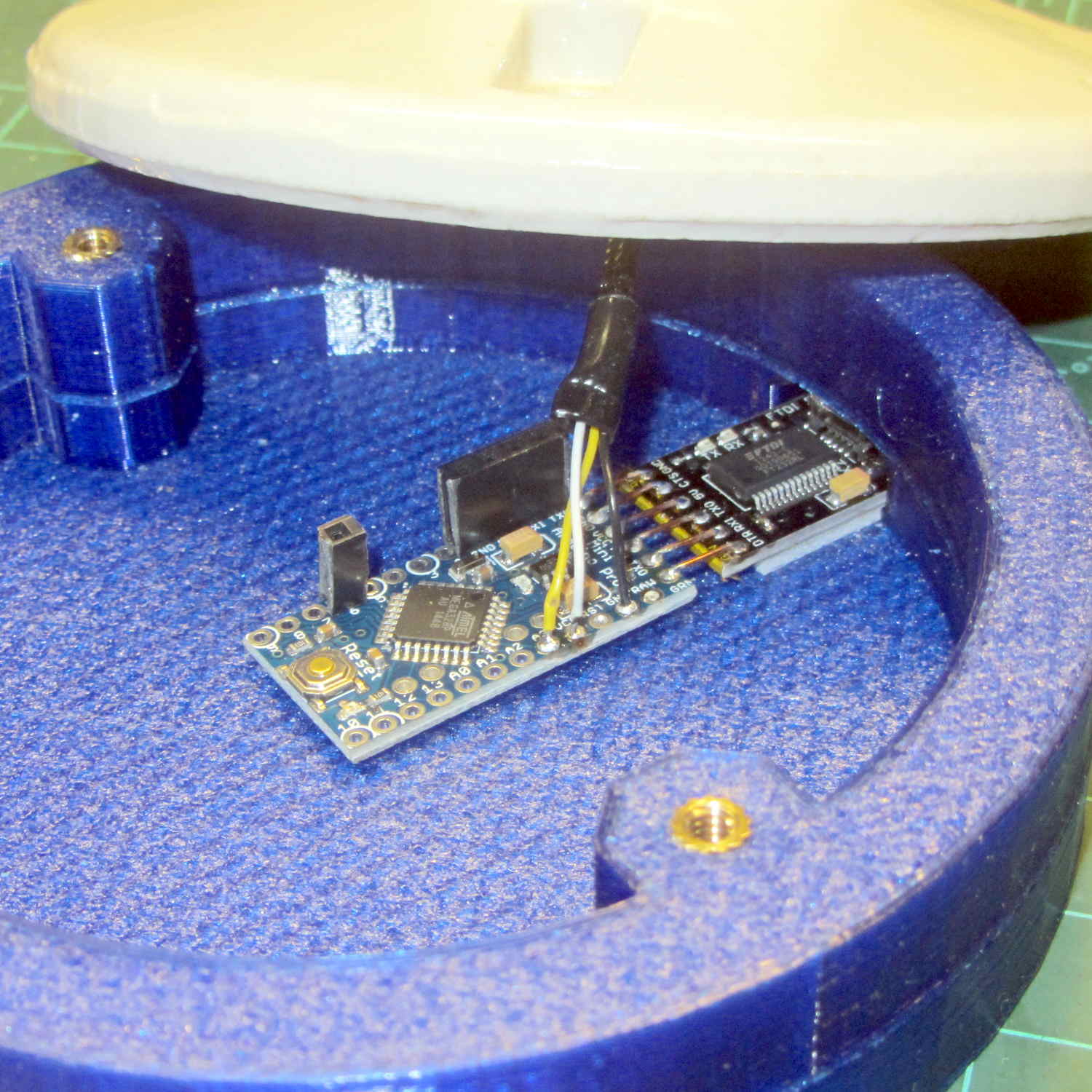
It turns out that 12 inches of wire inside PET braid barely reaches from the cap to the Arduino Pro Mini in the base:
Halogen bulb brass cap – Arduino Pro Mini
Next time, I’m going to add half a foot more wire than I think it can possibly require, with PET braid to suit.
A thin ring of clear epoxy holds the “heatsink” at the dead center of the bulb. It lights up a bit more than I expected, so opaque epoxy may be in order:
Halogen bulb brass cap – detail red
It’s still too big to suit even the big 21HB5A tubes, but brass definitely wins over plastic!
That blue PETG base has become the least-attractive part of the lamp, but it’s survivable for now.
Epoxy a snippet of brass tubing from the Bottomless Bag o’ Cutoffs into the hole:
Ersatz aluminum heatsink – tubing trial fit
Recycle the old wire and PET loom, solder to another fake Neopixel, blob epoxy inside to anchor everything, and press it into place:
Ersatz aluminum heatsink – epoxying LED
Cutting the failed LED & plastic heatsink off the wire left it a bit too short for that tall bulb, but some rummaging in the heap produced a 100 W incandescent floodlight with a nicely pebbled lens:
Reflector floodlight – overview
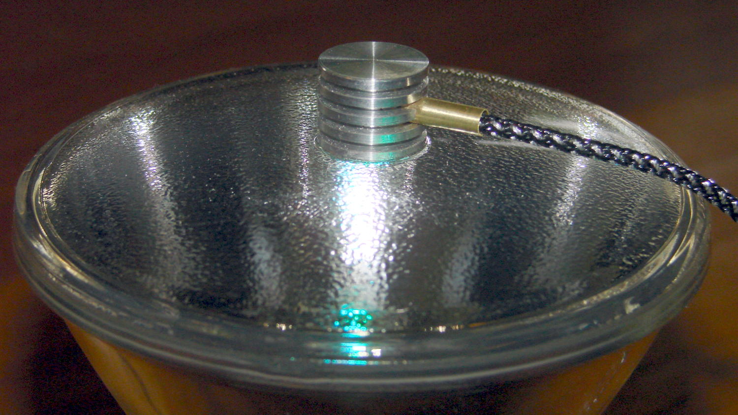
A thin ring of clear epoxy secures the ersatz heatsink to the floodlight:
Reflector floodlight – finned LED holder
This time, I paid more attention to centering it atop the General Electric logo ring in the middle of the lens, which you can just barely see around the perimeter of the aluminum fin. By pure raw good fortune, the cable ended up pointed in the general direction of the socket’s pull-chain ferrule; you can’t unscrew the bulb without tediously unsoldering the wires from connector atop the knockoff Pro Mini inside the base and squeezing them back out through the ferrule.
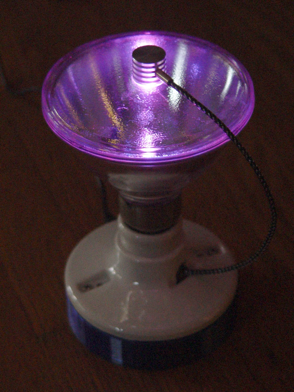
With the firmware set for a single fake Neopixel on pin A3 and a 75 ms update rate, the floodlight bowl fills with color:
Reflector floodlight – purple phase
It puts a colored ring on the ceiling and lights the whole room far more than you’d expect from 200 mW of RGB LEDs.
The QC post and tool holders have very nice machining and surface finish; they evidently come from an entirely different production line than the lathe components. I can definitely get used to using carbide inserts, although I ordered some HSS inserts for interrupted cuts.
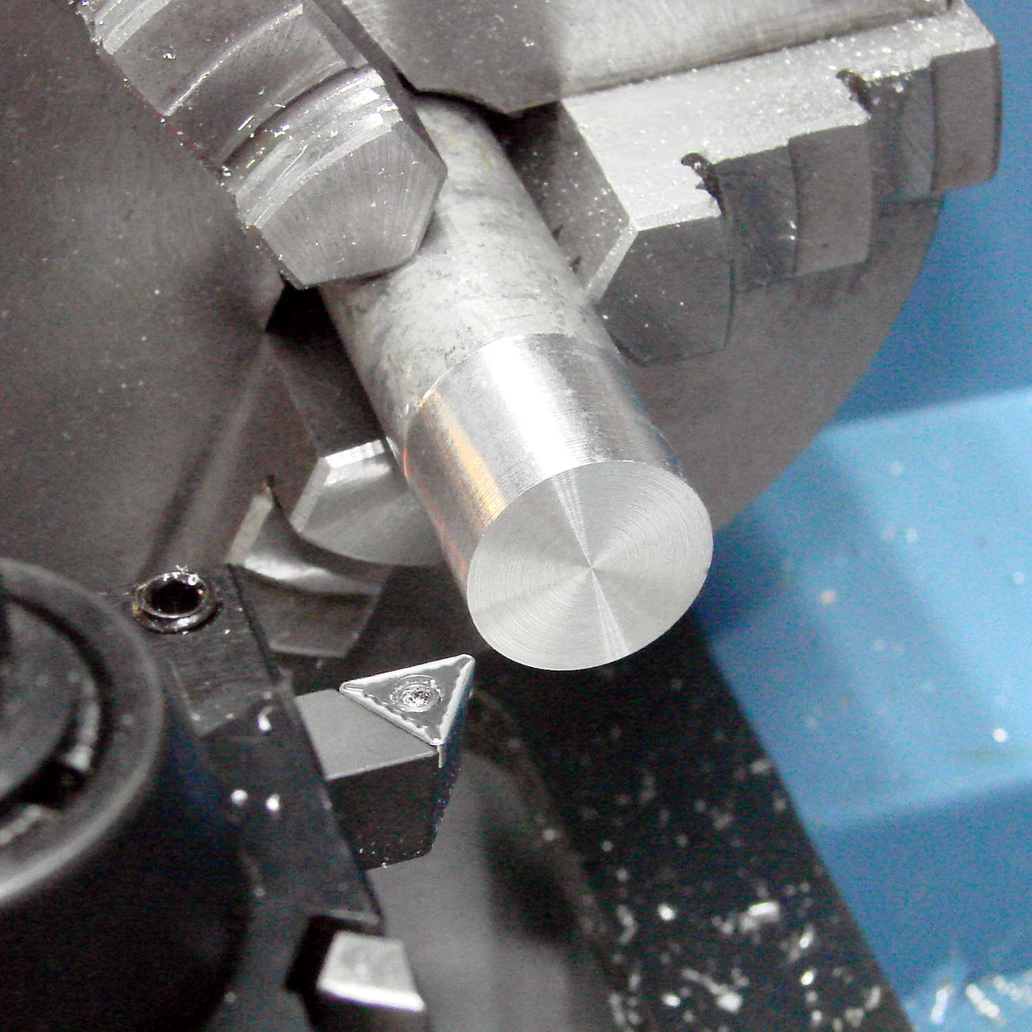
The HSS cutoff tool does what you’d expect:
LMS Mini-lathe – first cut – drilled and slotted
The holes in the end came from short (“screw machine”) drill bits I got for the Sherline’s painfully limited Z axis travel. Even so, chucking one in the 1/2 inch capacity LMS drill chuck shows why a 16 inch bed isn’t excessive:
LMS Mini-lathe – drill chuck vs bed length
The 6 inch = 150 mm scale on the bed (to the right of the tailstock) extends to the limit of tailstock travel, so you could have another half foot of stock sticking out of the 3 jaw chuck. A collet in the spindle would give you another two inches, but it’s snug in there.
On the other paw, this is a little lathe intended to make little things. It’ll do fine…
Having that knockoff Neopixel fail from overheating prompted me to measure what was going on. Because the LEDs sink most of their heat into the package leads, the back of the LED strip should be the hottest part of the package and the Mood Light’s central pillar should be pretty nearly isothermal. Despite that, I figured I should measure the temperature closer to the back of the strip, sooo I drilled a hole for the thermocouple…
Clamp the whole Mood Light to the Sherline’s tooling plate with the pillar sides mostly square to the axes and line up the spindle 2 mm behind the LED strip:
Mood Light – aligning thermocouple hole
The two clamp pads are CD chunks, under just enough pressure to anchor the Mood Light.
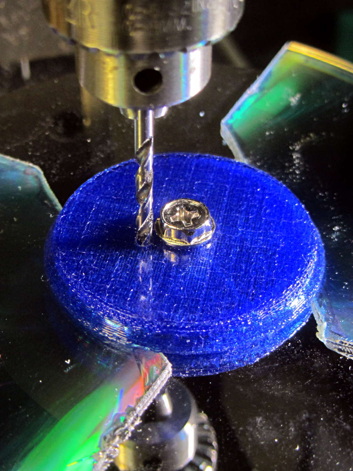
Screw the cap in place (to match-drill both holes at once) and drill a 2 mm (#46, close enough) hole down past the top LED:
Mood Light – drilling thermocouple hole
I tucked the Mood Light into a box to ward off breezes, jammed one thermocouple into the new hole, let another float over the top platter, then forced the Neopixels to display constant grayscale PWM values (R=G=B) while recording the LED and air temperatures every five minutes:
Hard Drive Mood Light – temp vs power data
That was easier and faster than screwing around with automated data collection. The data has some glaring gaps where I went off to do other things during the day.
I turned those numbers into a graph, printed it out, puzzled over it for a bit, then annotated it with useful numbers:
Hard Drive Mood Light – temp vs power data – graph
That first little blip over on the left comes from a minute or two at PWM 32; the cooling time constant works out to be a bit under 10 minutes. The warming time constant looks to be somewhat longer, but not by much.
Eyeballing the endpoint temperatures for each PWM value, feeding in the current measurements, and creating a small table:
VCC
5
V
Current
0.057
A
Package
0.285
W
Total
3.42
W
PWM
Duty
Nom Power
Failed LEDs
Net Power
°C Rise
0
0.00
0.00
0
0.00
0
32
0.13
0.43
0
0.43
6
64
0.25
0.86
0
0.86
12
85
0.33
1.14
1
1.04
16
128
0.50
1.71
1
1.62
24
192
0.75
2.57
1
2.47
35
255
1.00
3.41
4
3.03
42
The same blue LED that failed earlier dropped out again, plus another package (on a different strip) went completely dark shortly after I clobbered the LEDs with full power at PWM 255. The Net Power column deducts the power not used by the failed LEDs, under the reasonable assumption that the total heating depends on the number of active LEDs.
All the failed LEDs worked fine when they cooled to room temperature, so, whatever the failure mode might be, it’s not permanent. The skimpy WS2812B datasheet says bupkis about a protective thermal shutdown circuit, although it specs an 80 °C maximum operating junction temperature. I’ll stipulate a 20 °C temperature difference from junction to thermocouple at PWM 255, but that doesn’t explain the first blue LED failure at PWM 85.
Methinks these knockoffs will be much happier operating in the mid-30s.
Turning the last two columns of that table into a graph (minus the PWM 0 line to let the intercept float around) looks like I’m faking it:
Hard Drive Mood Light – Temperature vs Power
The Y intercept is off by less than 1 °C, which seems pretty good under the circumstances. The kink at PWM 85 shows that I probably didn’t allow enough time for the temperature to stabilize after the blue LED failed.
So, in round numbers, the thermal coefficient for a dozen knockoff Neopixels on a plastic pillar inside a stack of hard drive platters works out to 14 °C/W.
The raised sine waves in the Mood Light produce a long-term average PWM half of their maximum PWM. They’ve been perfectly happy with MaxPWM = 64 pushing them barely 6 °C over ambient, so they should continue to work fine at PWM 128 for a 12 °C rise… except, perhaps, during the hottest of mid-summer days.
Obviously, I should jam a thermistor inside the column and have the Arduino wrap a feedback loop around the column temperature…
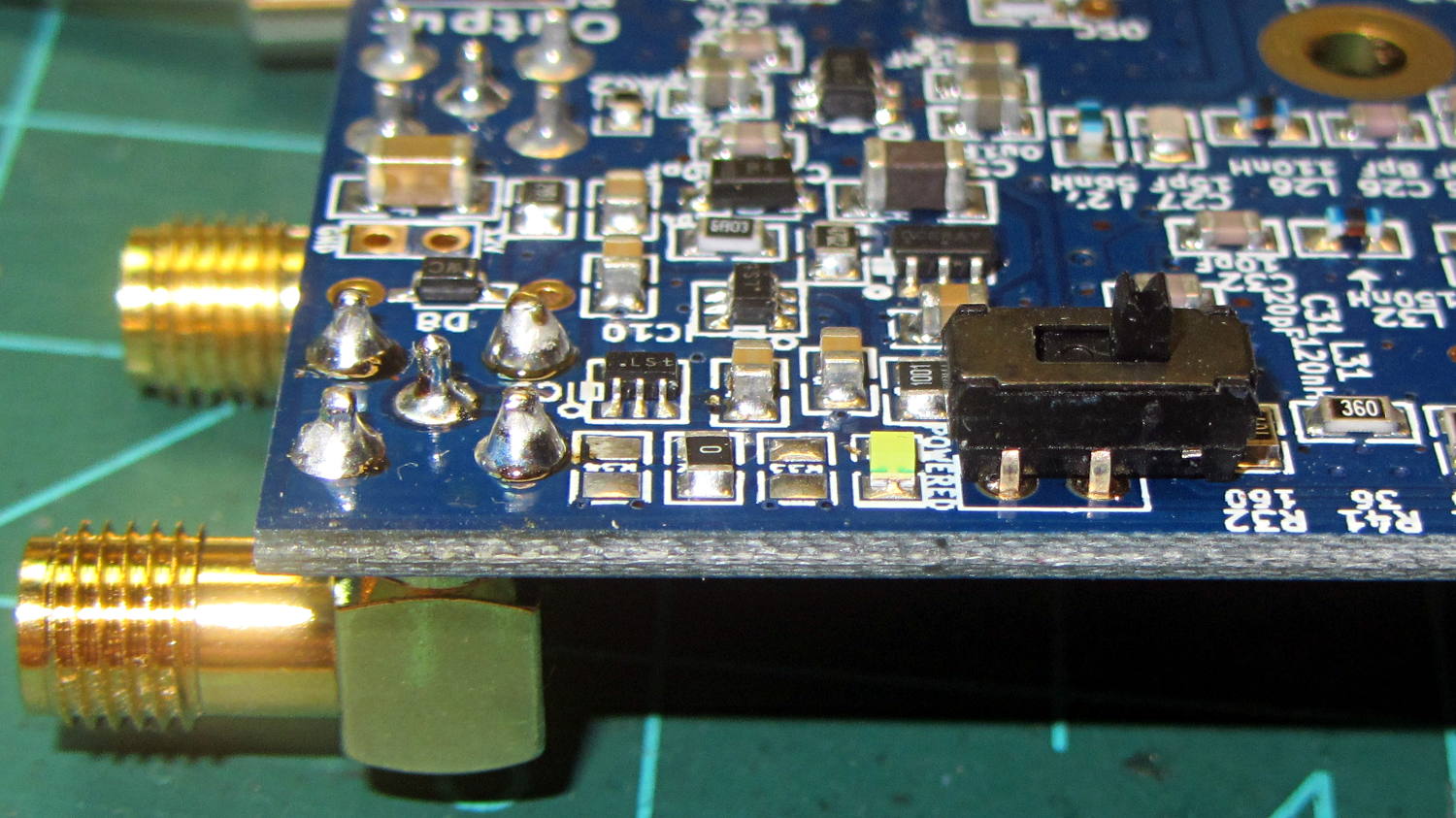
Some rummaging produced a tiny DPDT switch that actually fit the holes intended for a pin header on the recently arrived Ham It Up board, at least after I amputated 2/3 of the poor thing’s legs:
Ham-It-Up – noise source switch – B
The new SMA noise output jack sits in the front left, with the white “noise on” LED just left of the switch:
Ham-It-Up – noise source switch – A
There’s no way to measure these things accurately, at least as far as I can tell, but the holes came out pretty close to where they should be. The new SMA connector lined up horizontally with the existing IF output jack and vertically with the measured / rounded-to-the-nearest-millimeter on-center distance:
Ham It Up – noise SMA drilling
The Enable switch doesn’t quite line up with the LED, so the holes will always look like I screwed up:
Ham-It-Up – noise source switch – case holes
That’s OK, nobody will ever notice.
Now, to stack up enough adapters to get from the SMA on the Ham It Up board to the N connector on the spectrum analyzer …