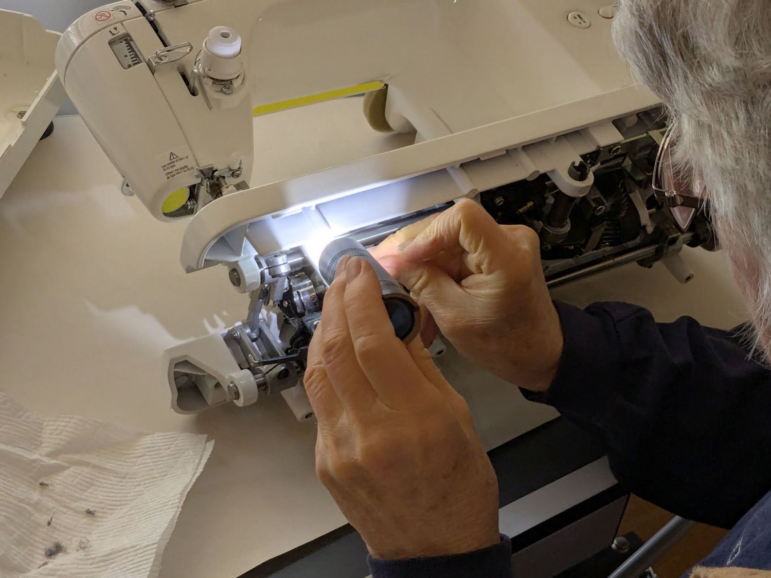
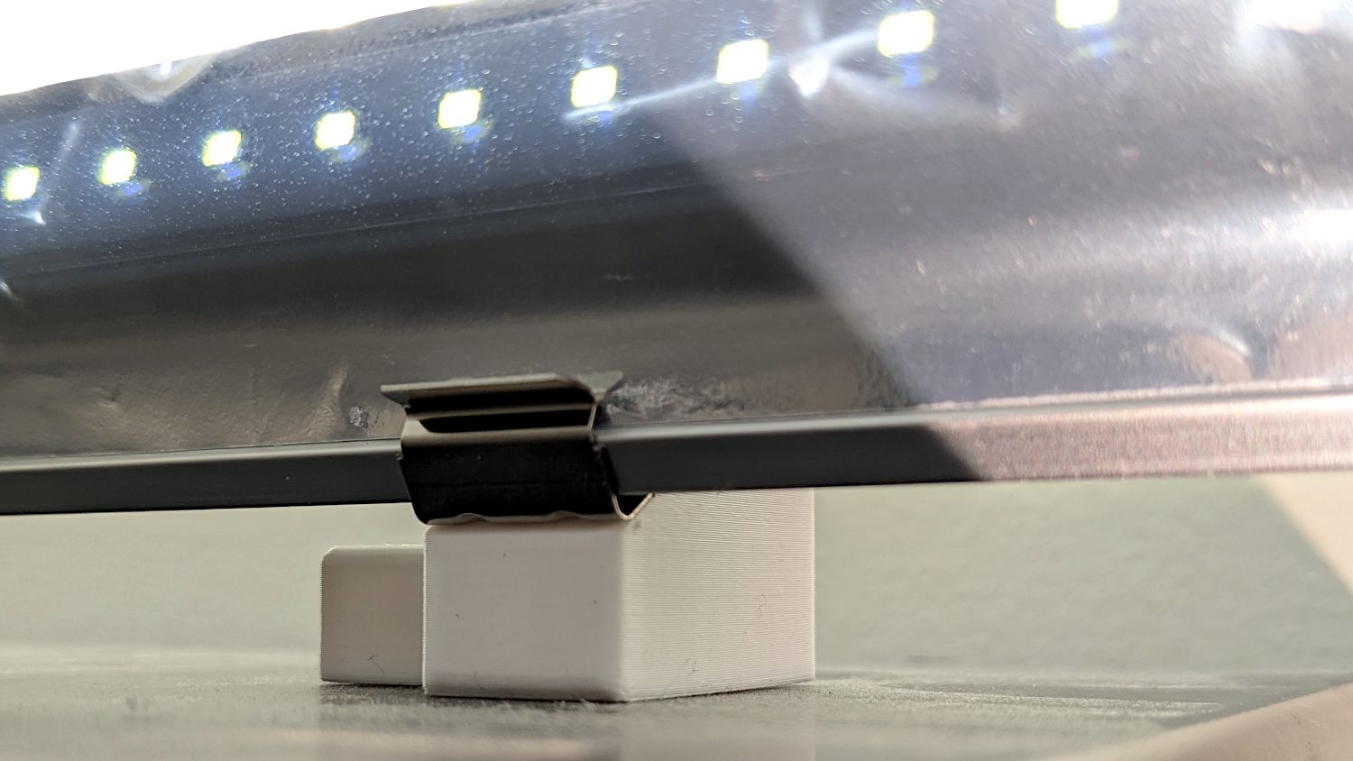
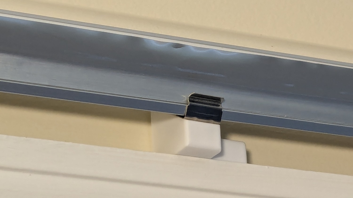
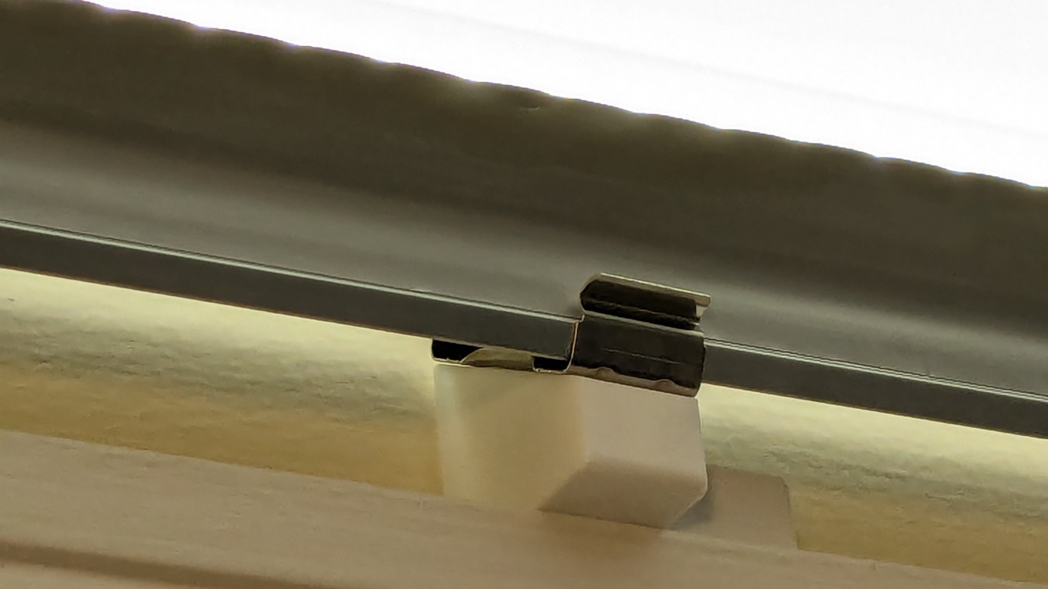
Mary wanted a horizontal spool adapter mounted closer to the front of her HQ Sixteen, in the M5 threaded hole where the Official Horizontal Adapter would go:
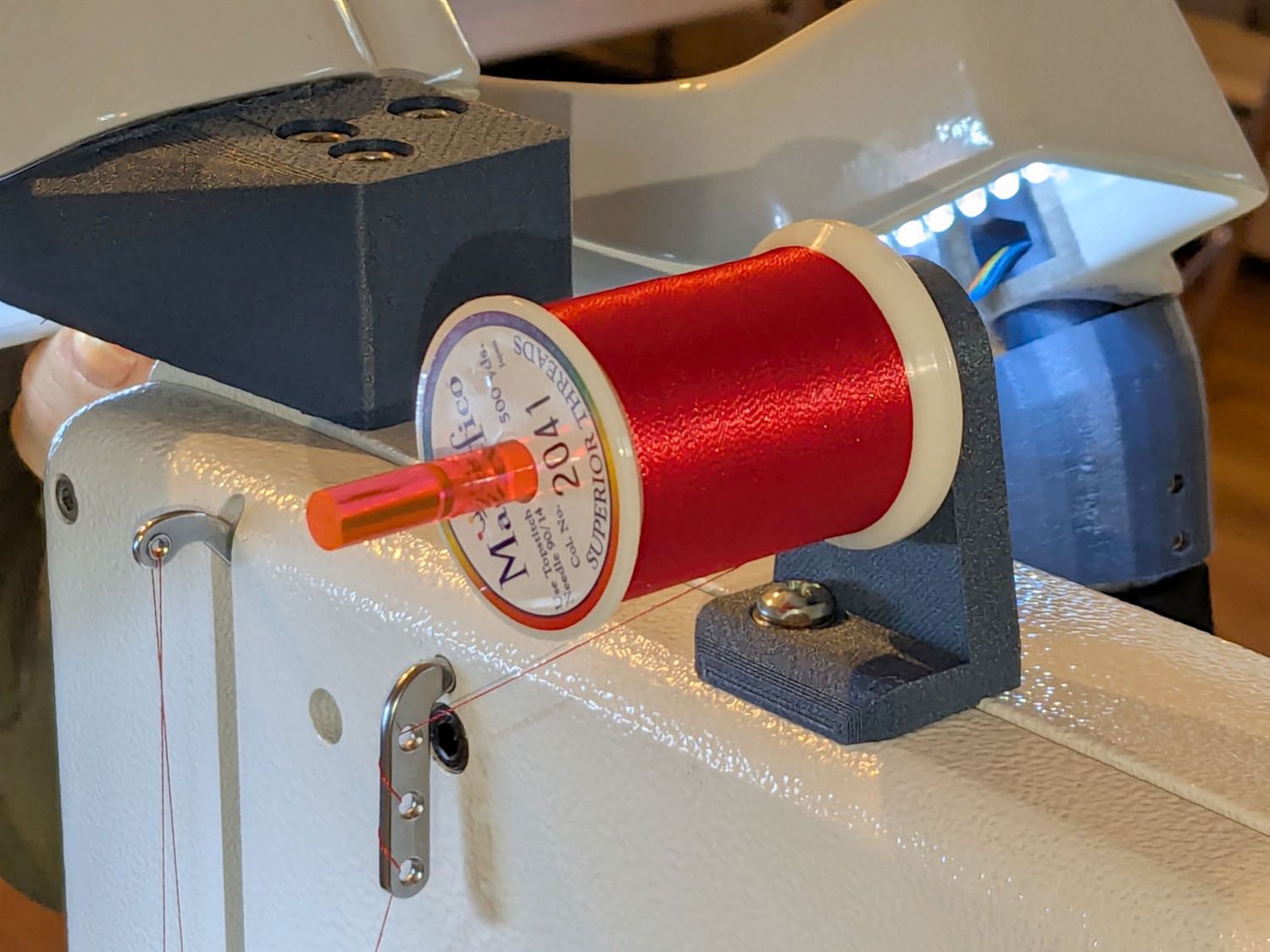
Yes, the pin through the spool is fluorescent edge-lit orange acrylic that looks wonderful in sunlight and is much more amusing than the black rod in the adapter atop the power supply pod.
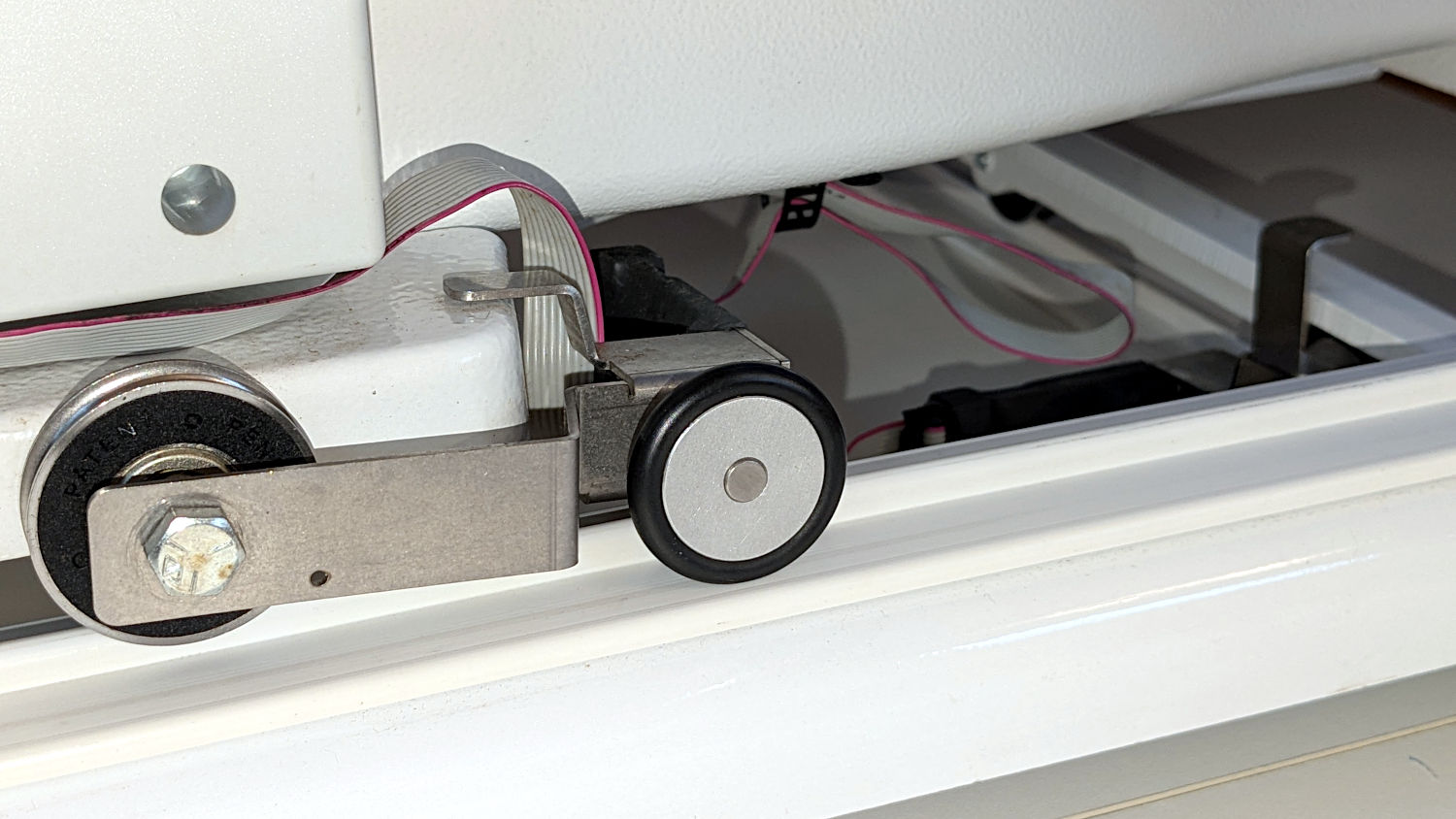
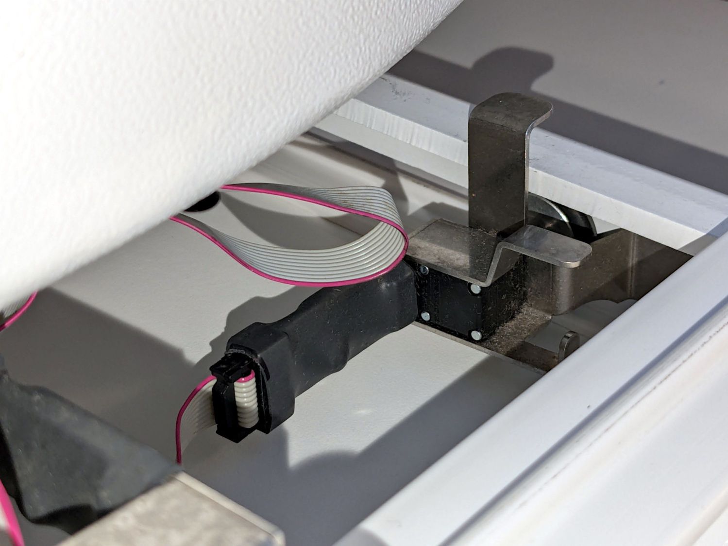
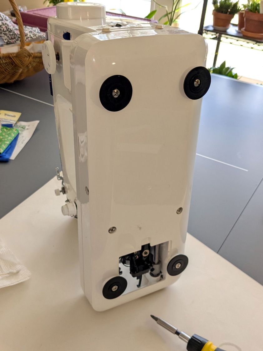
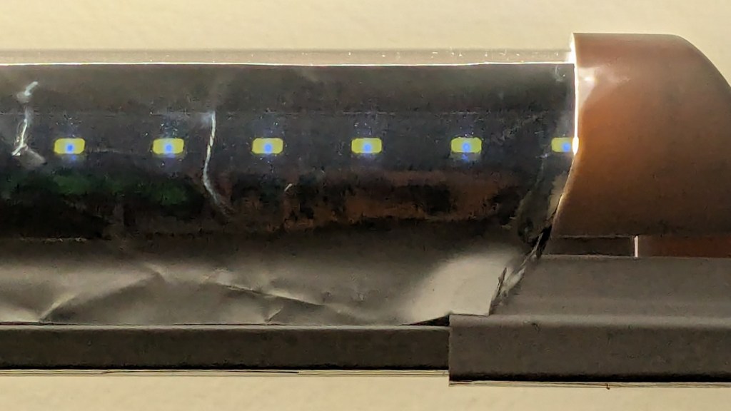
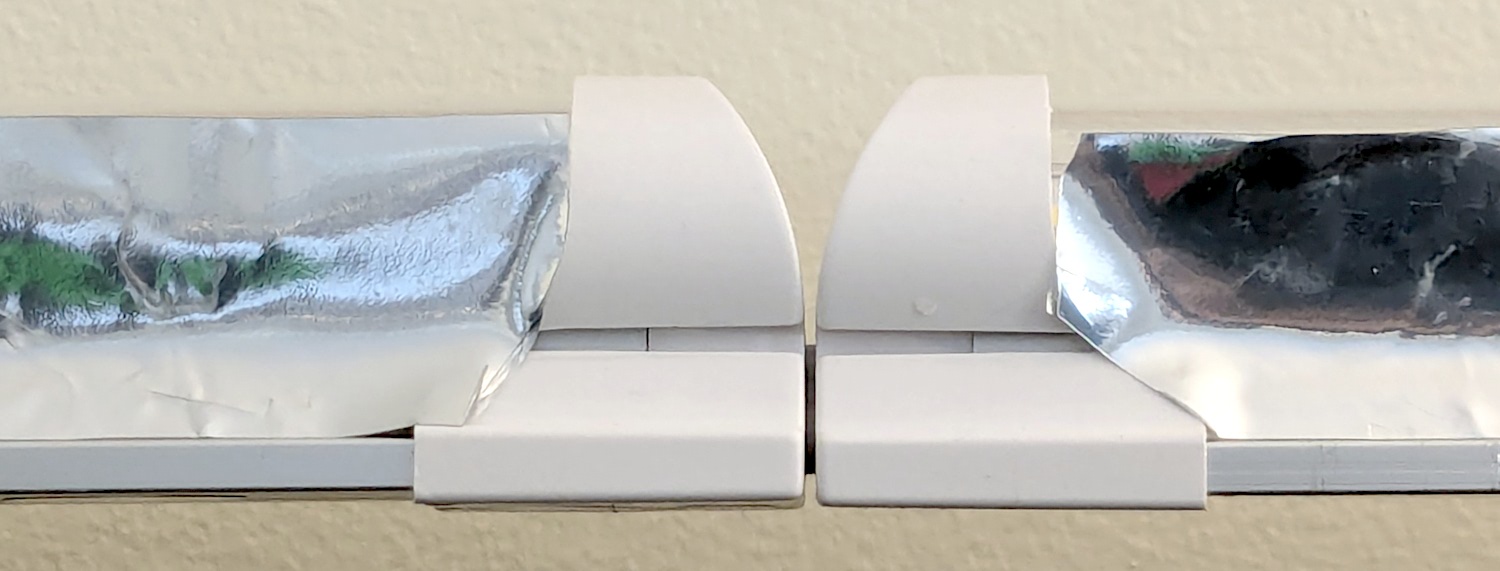
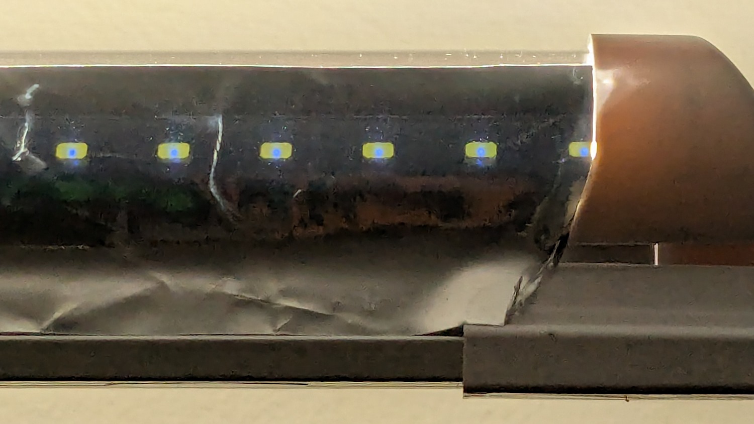
The top of the machine case is not flat, level, or easy to model, so I deployed the contour gauge again, with some attention to keeping the edge pins parallel & snug along the machine sides:
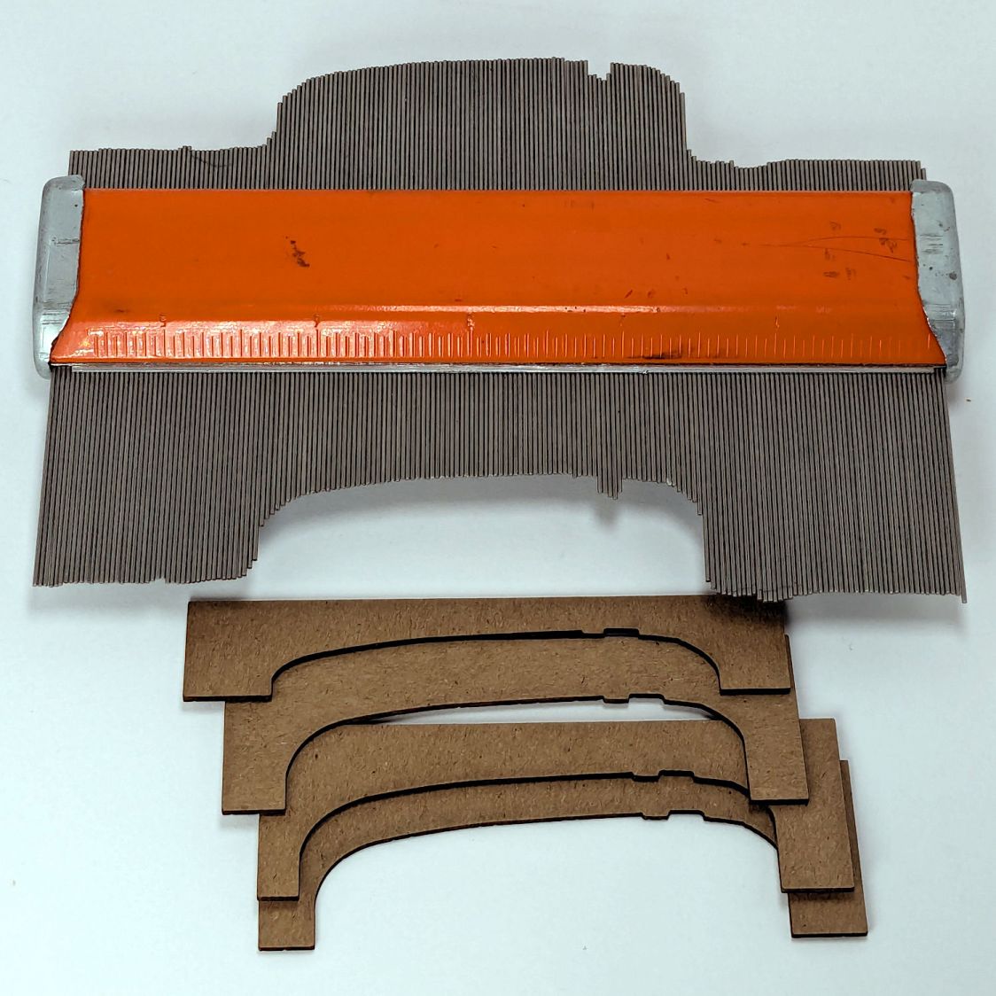
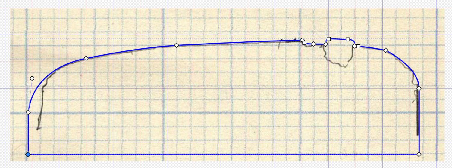
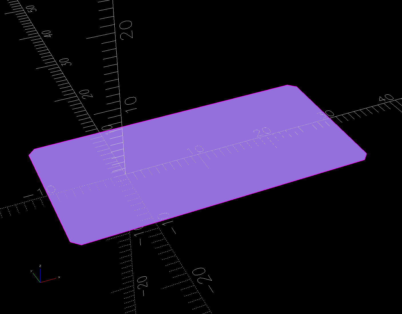
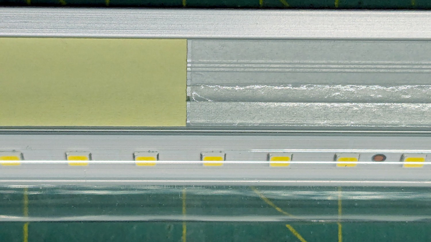
Tracing the edge of the pins onto paper, scanning, and feeding it into Inkscape let me lay a few curves:
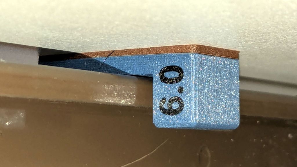
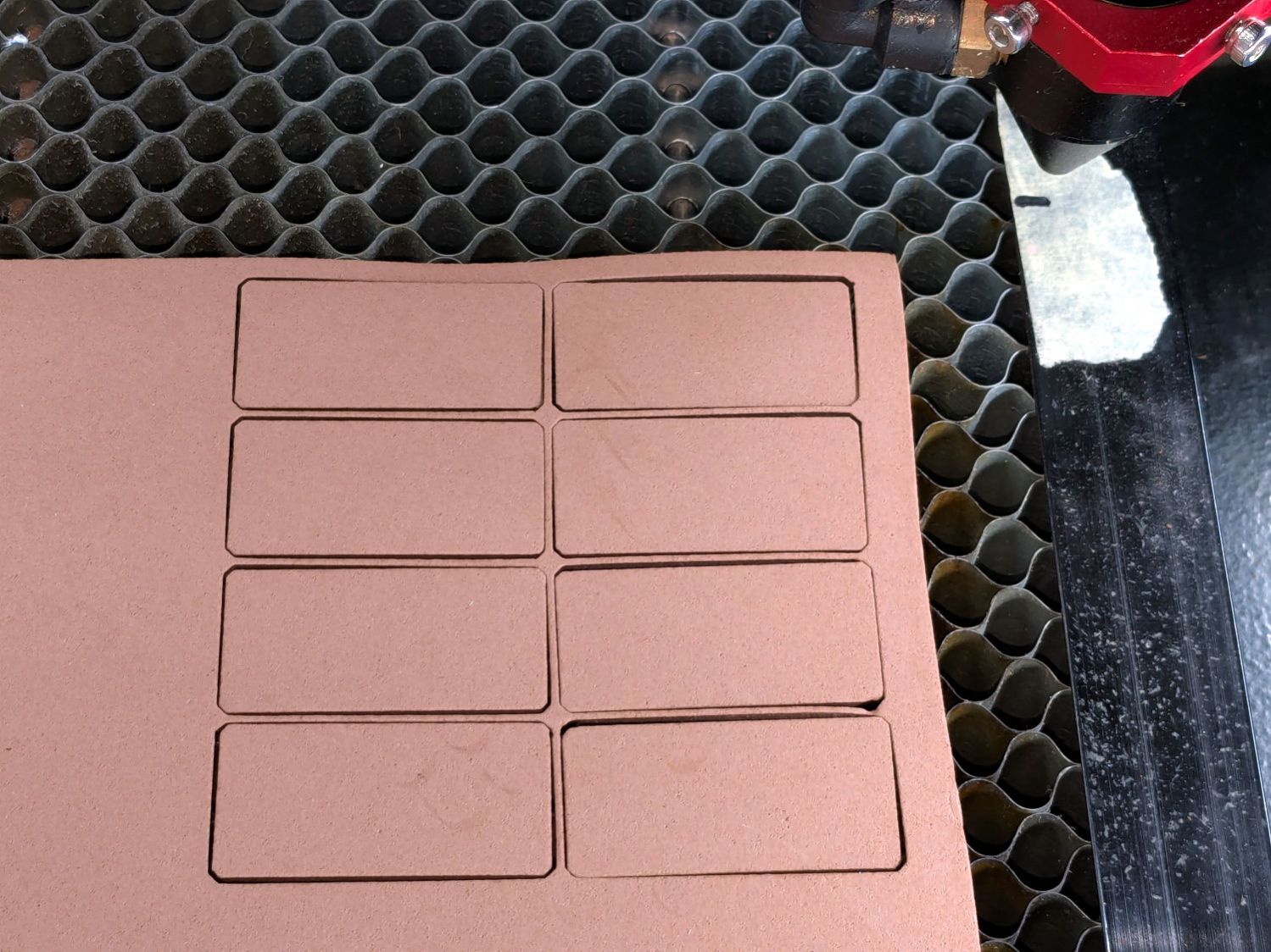
The laser-cut chipboard test pieces show the iterations producing closer and closer fits to the machine.
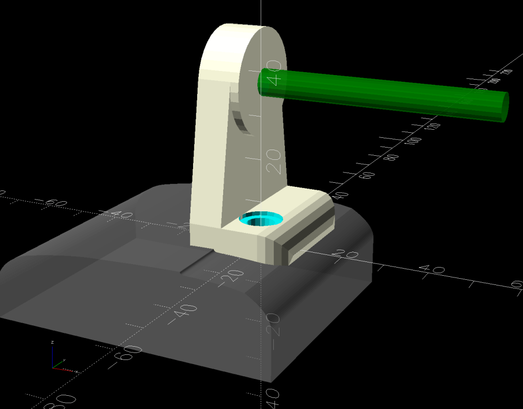
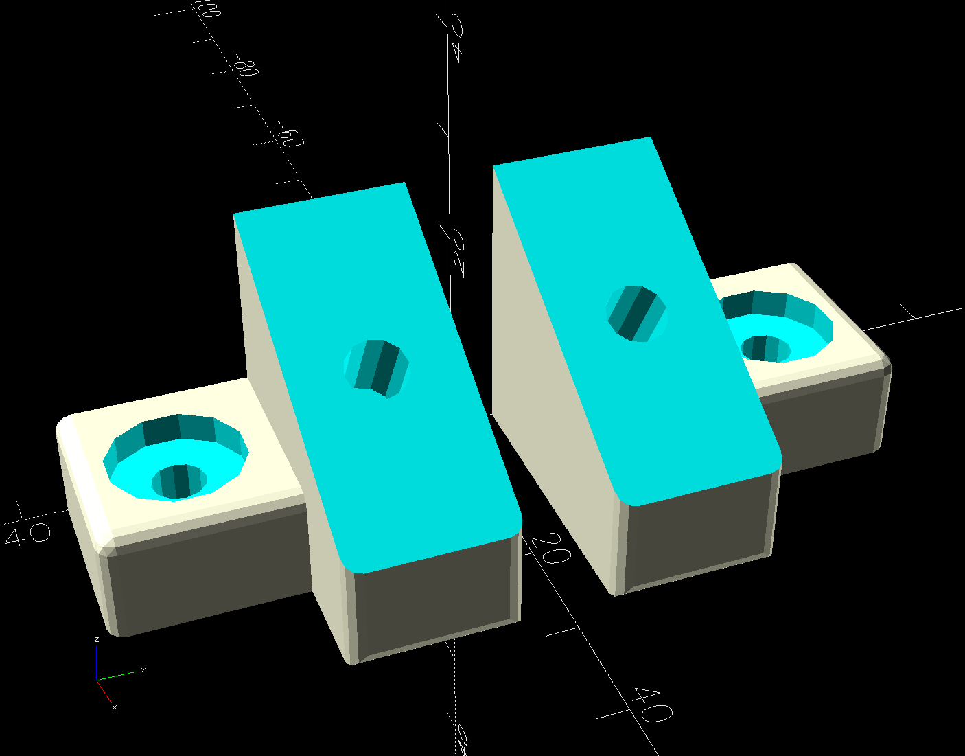
Importing the final SVG image into OpenSCAD and extruding it produced a suitable solid model of the machine’s case:
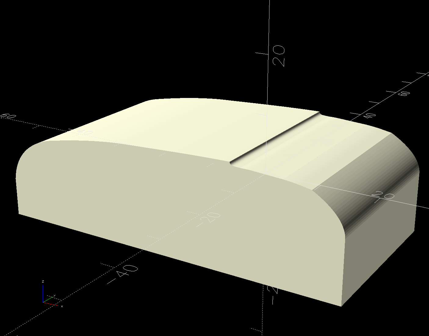
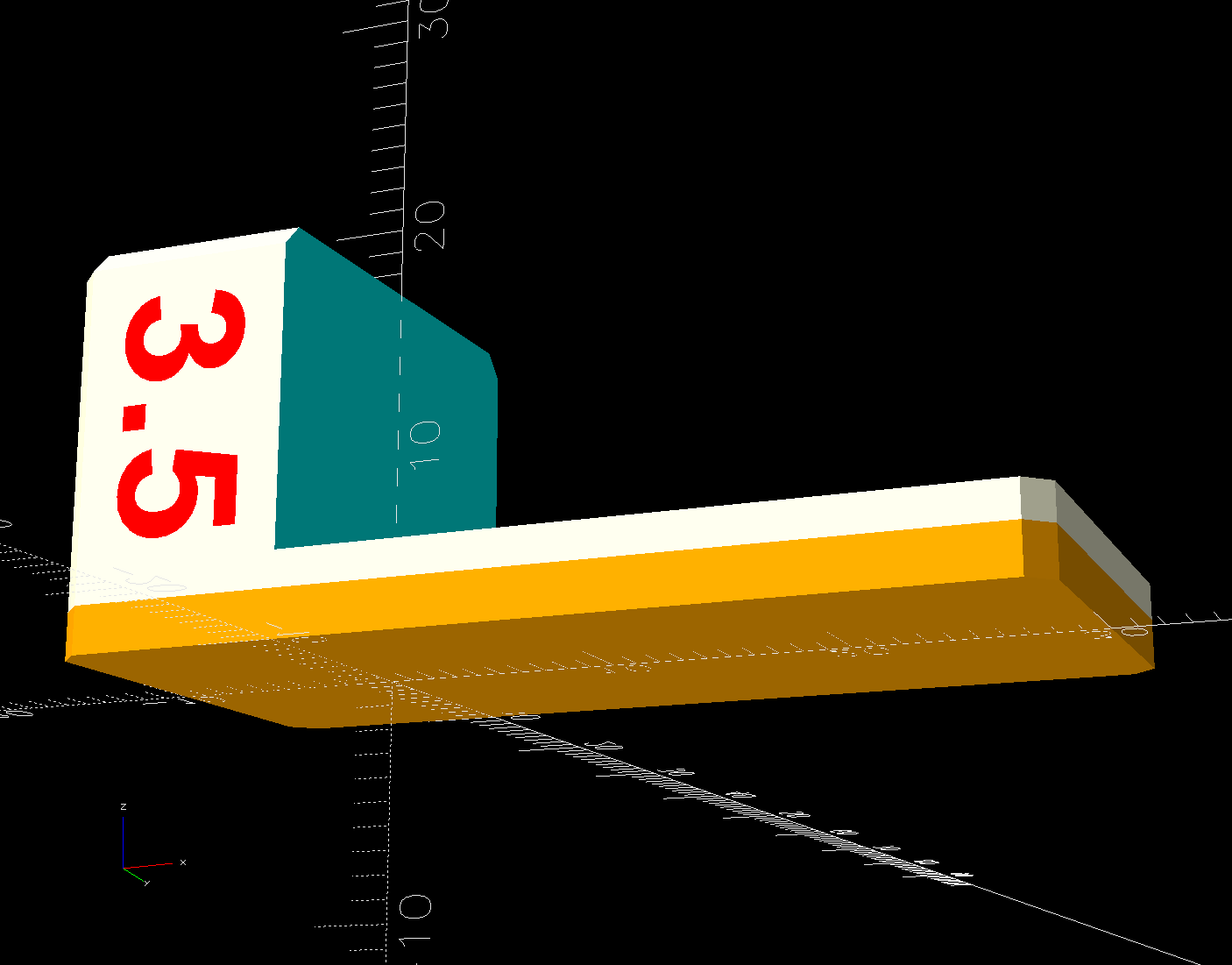
Subtract that shape from the bottom of the adapter to get a perfect fit atop the machine:

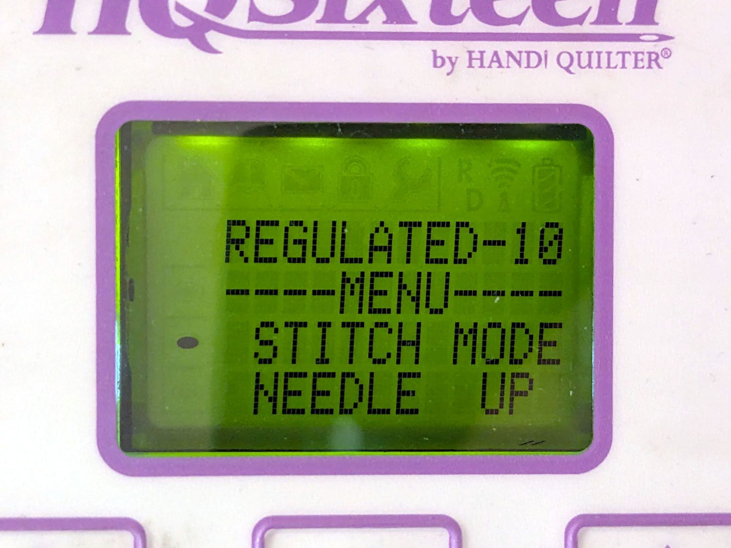
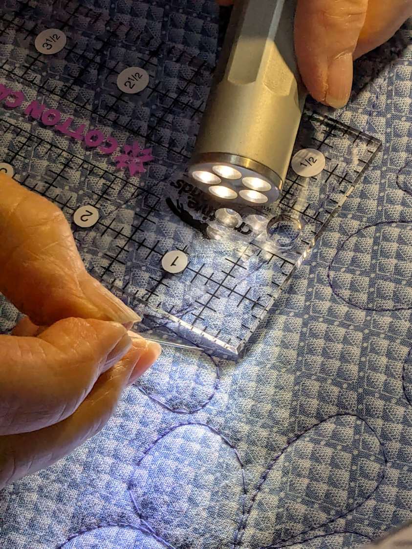
Early results are encouraging, although the cheap polyester thread Mary got from a friend’s pile and is using for practice untwists itself after passing through the tension disks on its way to the needle. She’ll load much better thread for the real quilt.
The OpenSCAD source code and SVG of the HQ Sixteen’s top profile as a GitHub Gist:
| // HQ Sixteen – horizontal thread spool adapter for front pin | |
| // Ed Nisley – KE4ZNU | |
| // 2025-04-07 | |
| include <BOSL2/std.scad> | |
| Layout = "Show"; // [Show,Build,Base,Wall,Frame] | |
| /* [Hidden] */ | |
| Protrusion = 0.1; | |
| HoleWindage = 0.2; | |
| ID = 0; | |
| OD = 1; | |
| LENGTH = 2; | |
| WallThick = 8.0; | |
| BaseThick = 12.0; | |
| Washer = [5.0,10.0,1.0]; // M5 washer | |
| Spool = [0.25*INCH,50.0,55.0]; // maximum thread spool | |
| SpoolClearance = [2.0,5.0,5.0]; // spool pin pointed to +X axis | |
| SpoolPin = [Spool[ID],Spool[ID],Spool[LENGTH] + WallThick + SpoolClearance.x]; | |
| BasePlate = [WallThick + SpoolClearance.x + 13.0, // X flush with side of machine | |
| Spool[OD]/2 + 2*SpoolClearance.y, | |
| BaseThick]; | |
| BaseOffset = [-(BasePlate.x – Washer[OD]),-Washer[OD],0.0]; // left front corner w.r.t. pin | |
| SpoolOC = [0, // relative to left front top of Base | |
| BasePlate.y/2, | |
| SpoolClearance.z + Spool[OD]/2 + BaseThick/2]; | |
| //———- | |
| // Construct the pieces | |
| // HQ Sixteen top frame profile | |
| // Aligned with hole somewhere along X=0, front edge at Y=0 | |
| // Lengthened slightly to cut cleanly | |
| module MachineFrame(Length=BasePlate.y + 2*Protrusion) { | |
| back(BasePlate.y + Protrusion) xrot(90) | |
| linear_extrude(height=Length,convexity=5,center=false) | |
| import("HQ Sixteen – top profile curve.svg",layer="Top Profile"); | |
| } | |
| // Baseplate | |
| // Aligned with hole one washer diameter in from corner | |
| module Base() { | |
| $fn=18; | |
| difference() { | |
| fwd(Washer[OD]) | |
| difference() { | |
| right(Washer[OD]) | |
| cuboid(BasePlate,anchor=RIGHT+FRONT+CENTER,rounding=BaseThick/2,edges=RIGHT); | |
| MachineFrame(); | |
| } | |
| down(BasePlate.z) | |
| cylinder(d=SpoolPin[OD] + HoleWindage,h=2*BasePlate.z); | |
| up(BasePlate.z/2 – Washer[LENGTH]) | |
| cylinder(d=Washer[OD] + HoleWindage,h=2*Washer[LENGTH]); | |
| } | |
| } | |
| // Wall holding spool pin | |
| module Wall() { | |
| $fn=36; | |
| translate(BaseOffset) { | |
| difference() { | |
| union() { | |
| translate(SpoolOC) | |
| right(WallThick) | |
| cylinder(SpoolClearance.x,d=Spool[OD]/2,orient=RIGHT); | |
| hull() { | |
| translate(SpoolOC) | |
| cylinder(WallThick,d=Spool[OD]/2,orient=RIGHT); | |
| up(BasePlate.z/2 – 1) | |
| cube([WallThick,BasePlate.y,1],center=false); | |
| } | |
| } | |
| translate(SpoolOC) left(Protrusion) | |
| cylinder(SpoolPin[LENGTH],d=SpoolPin[OD],orient=RIGHT); | |
| } | |
| } | |
| } | |
| module Adapter() { | |
| Base(); | |
| Wall(); | |
| } | |
| //———- | |
| // Show & build the results | |
| if (Layout == "Base") | |
| Base(); | |
| if (Layout == "Wall") | |
| Wall(); | |
| if (Layout == "Frame") | |
| MachineFrame(); | |
| if (Layout == "Show") { | |
| Adapter(); | |
| color("Gray",0.5) | |
| MachineFrame(60); | |
| color("Green",0.75) | |
| translate(BaseOffset) | |
| translate(SpoolOC) | |
| cylinder(SpoolPin[LENGTH],d=SpoolPin[OD],orient=RIGHT,$fn=18); | |
| } | |
| if (Layout == "Build") | |
| up(-BaseOffset.x) | |
| yrot(-90) | |
| Adapter(); | |


