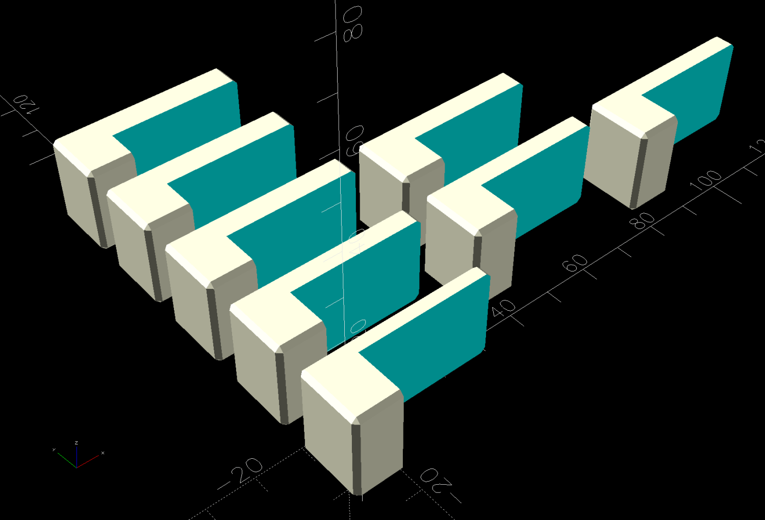
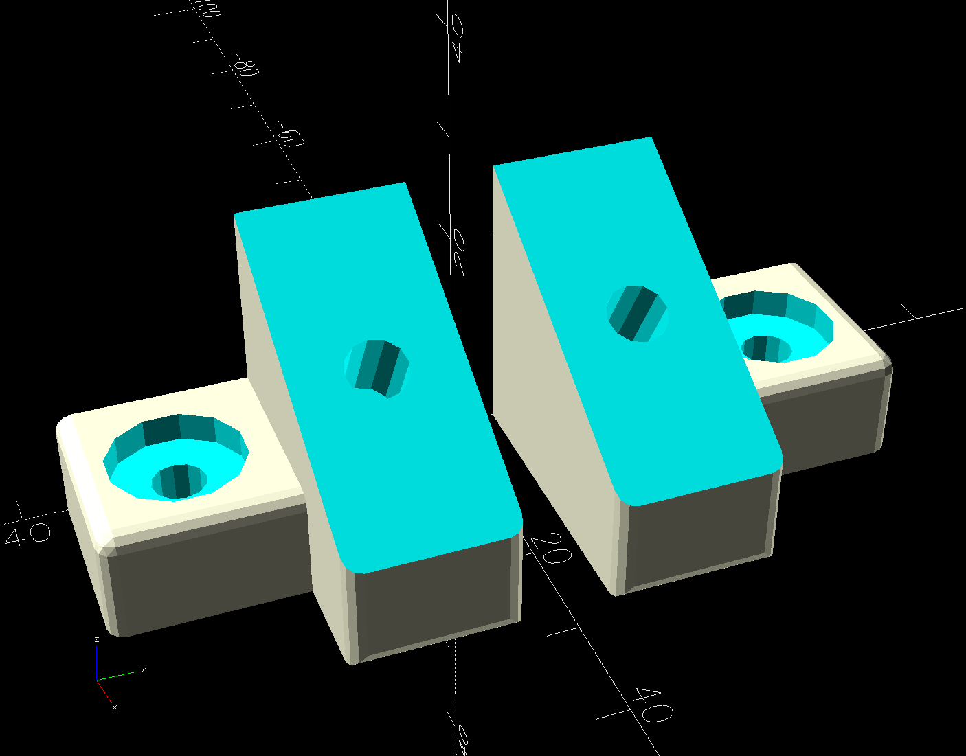
The object of the game being to tilt the LED strip lights at (maybe) 30° to put more light higher on the wall and further out on the ceiling, with the overriding constraint of no visible holes. Given their eventual home atop the window moulding along the front wall of the Living Sewing Room, these seemed adequate:
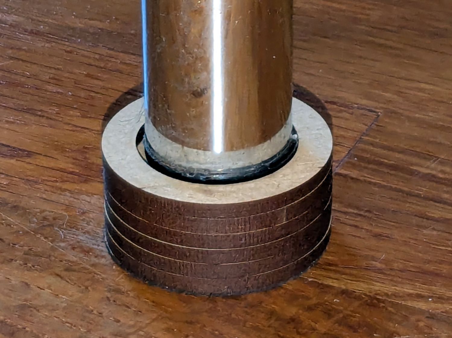
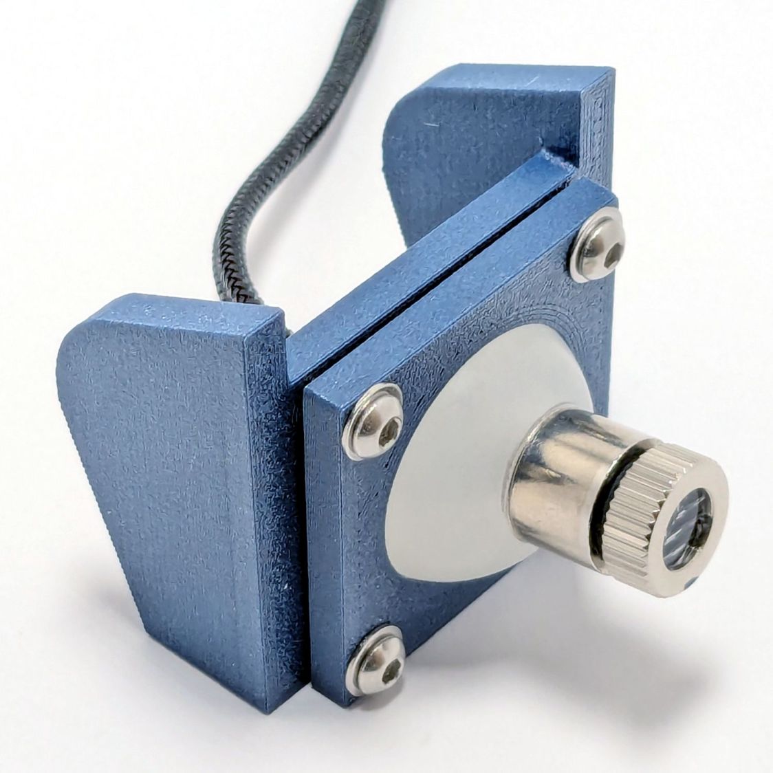
The hole on the angled part fits an M4 brass insert and the recessed holes capture the washer-like head of a sharp-point lath screw.
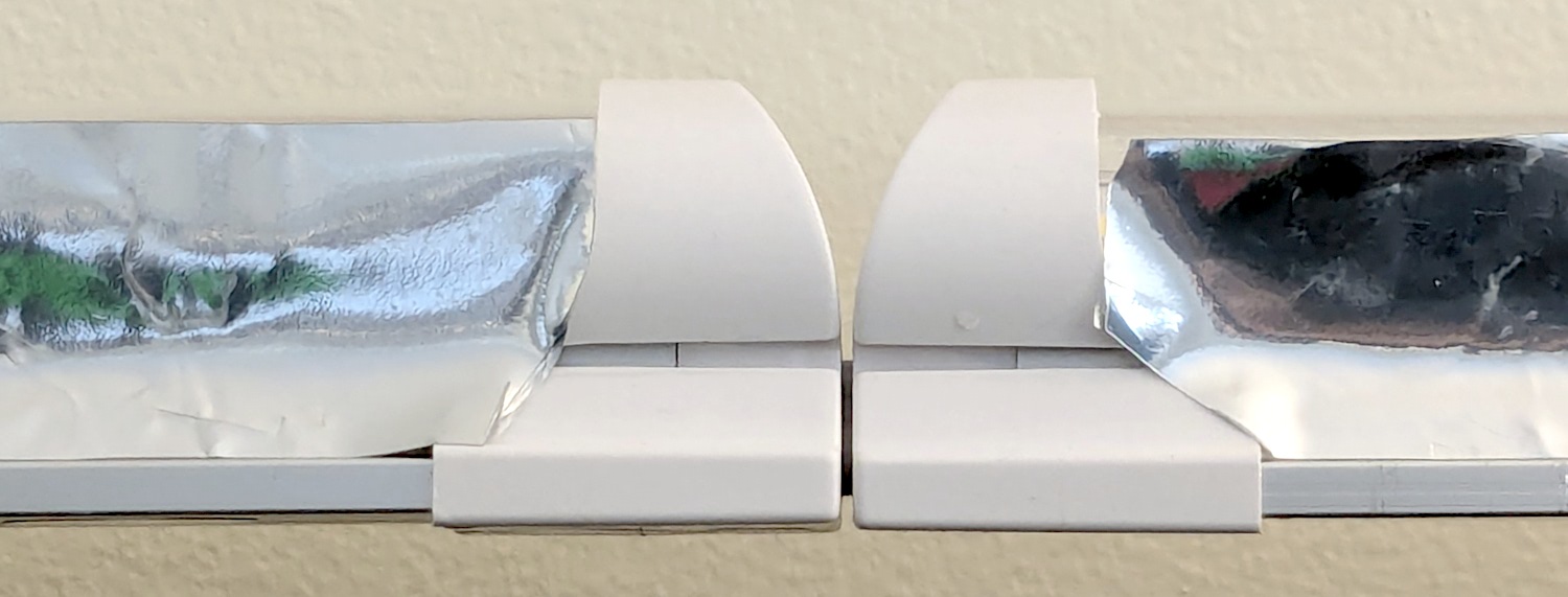
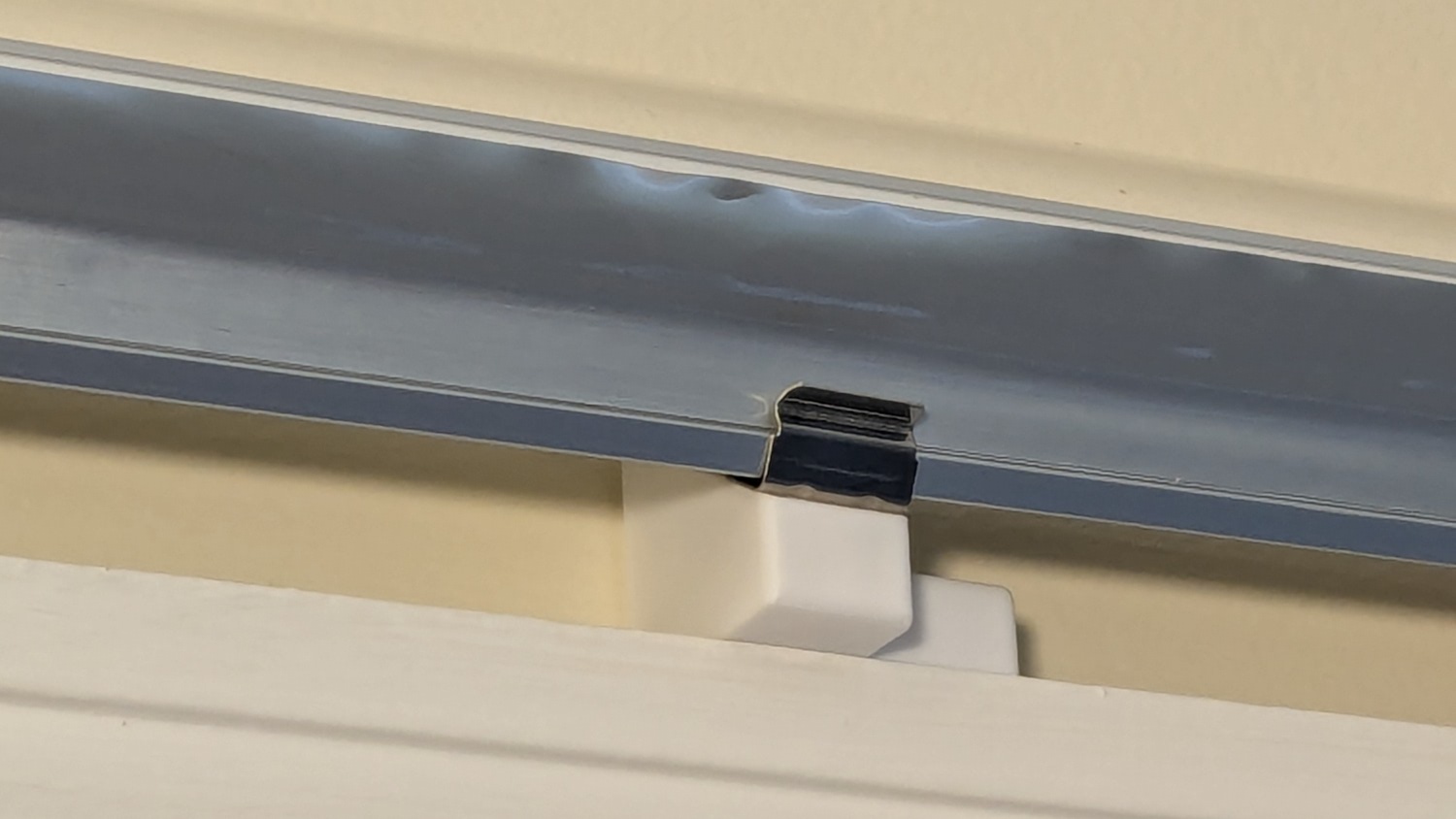
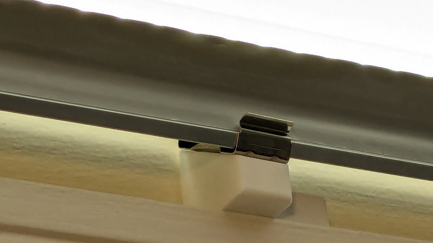
Two pairs applied to the lights sitting atop the Fabric Cabinets served to verify the fit:
They’re held firmly by the aluminum extrusion and don’t need a bigger footprint to remain stable.
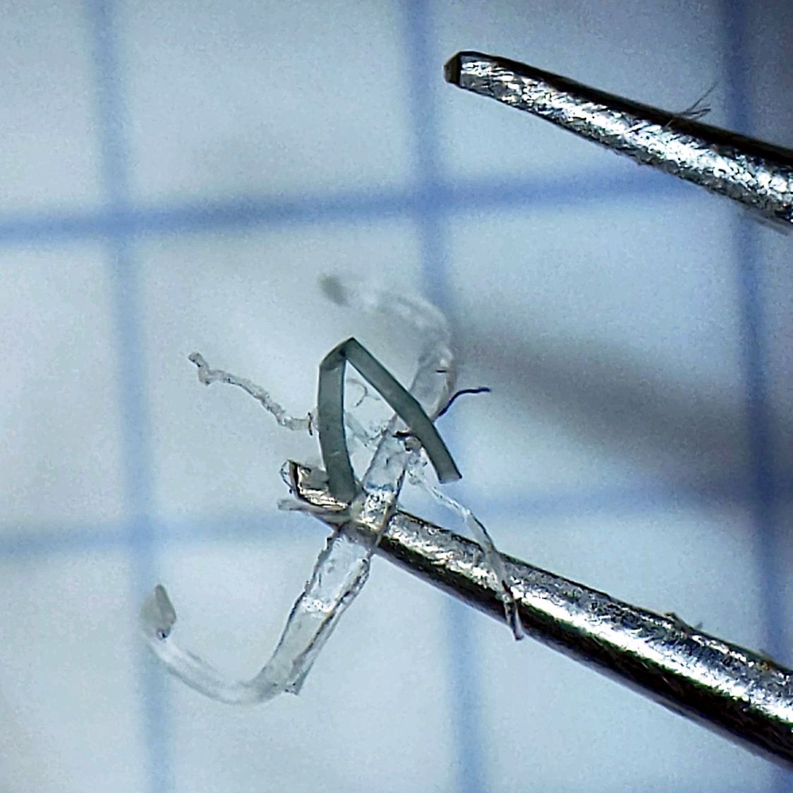
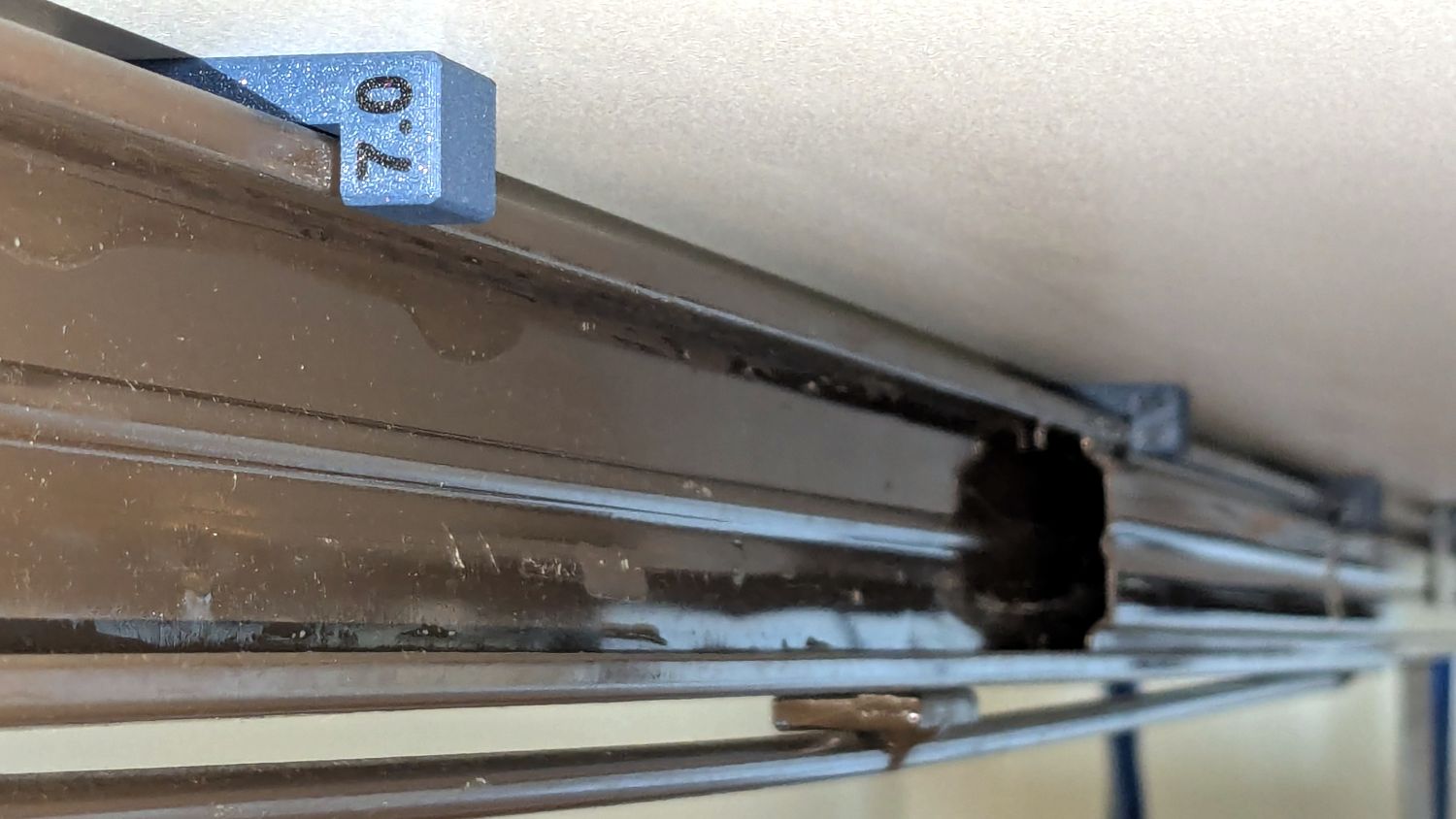
So I made another six, stuck on ⅞ inch strips of aluminized Mylar (cut from a bag in much better condition), and drilled holes where they can’t be seen:
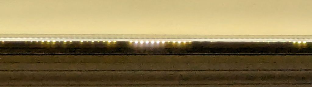
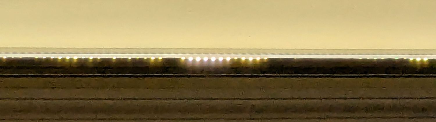
It’s almost too bright in there with 3 × 40 W of LED lights washing the wall and ceiling:
I don’t like the cold 6000 K color temperature, but Mary doesn’t mind it. They fill the Sewing Table with shadowless / glareless light, although that kind of light makes the place look like a store.
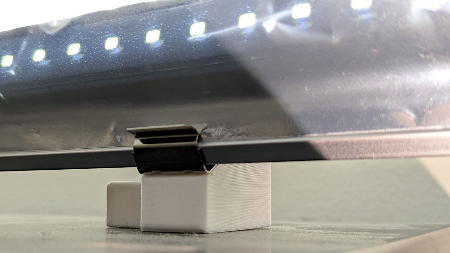
I think moving the strip lower and away from the wall could hide the entire mount from view.
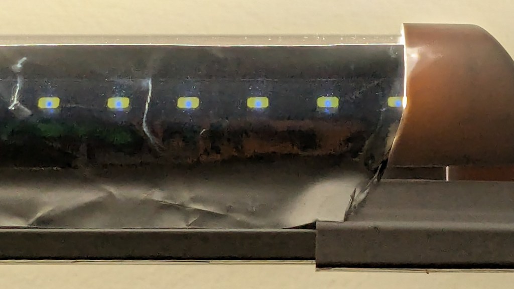
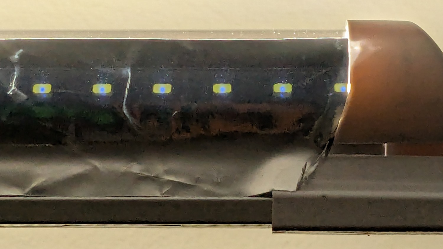
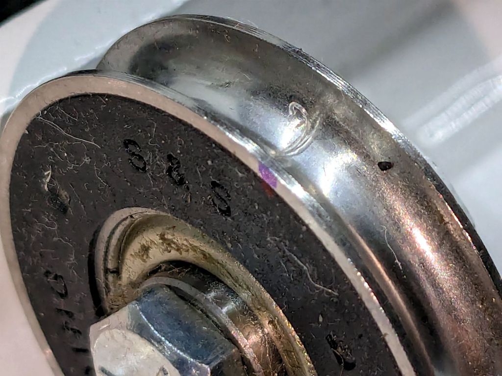
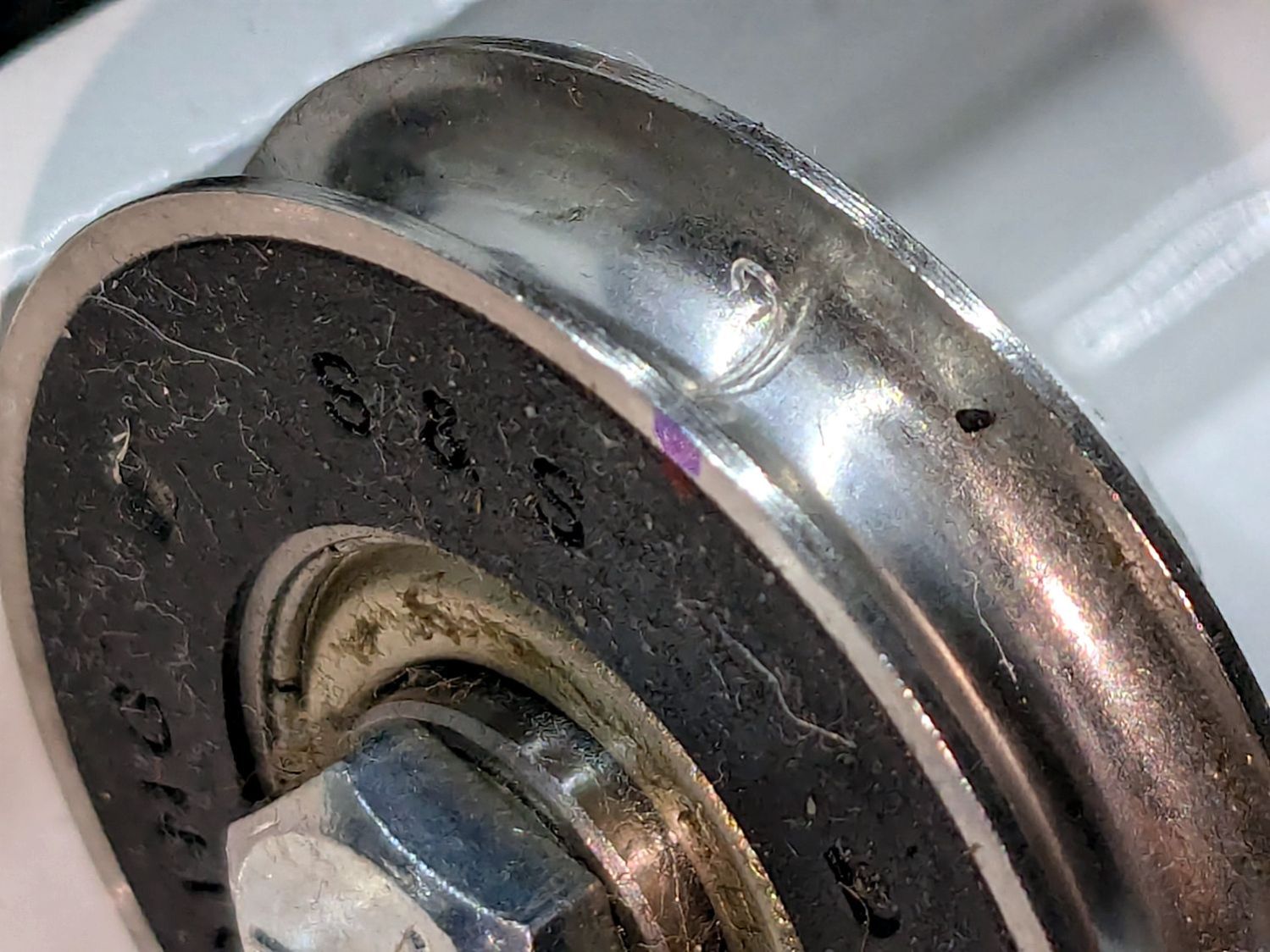
Contrary to what I expected, the Mylar reflectors must be at least an inch tall to avoid Baily’s Beads seen from across the room:
With all that in mind, we’ll run these for a while to shake out any other improvements.
The OpenSCAD source code as a GitHub Gist:
| // LED light bar mounts | |
| // Ed Nisley – KE4ZNU | |
| // 2025-03-16 | |
| include <BOSL2/std.scad> | |
| Layout = "Show"; // [Show,Build,ScrewMount,BarMount] | |
| BaseAngle = 30; // [0:50] | |
| /* [Hidden] */ | |
| ID = 0; | |
| OD = 1; | |
| LENGTH = 2; | |
| Protusion = 0.1; | |
| NumSides = 3*4; | |
| Radius = 1.5; | |
| $fn = NumSides; | |
| MouldWidth = 18.0; // nominal (3/4) * INCH, but lots of paint slop | |
| MouldScrew = [4.7,12.0,2.6]; // clearance, head OD, head thick | |
| Insert = [4.0,5.5,6.0 + 3.0]; // heat-set brass without pilot end | |
| BarClip = [33.0,15.0,11.0]; // snaps around led base | |
| ScrewBlockOA = [MouldWidth,MouldScrew[OD] + 2*Radius + 2.0,10.0]; | |
| BarBlockOA = [BarClip.x*cos(BaseAngle),15.0,BarClip.x*sin(BaseAngle) + 2*ScrewBlockOA.z]; | |
| Gap = 2.0 + max(ScrewBlockOA.y,BarBlockOA.y); | |
| //———- | |
| // Define shapes | |
| module ScrewMount() { | |
| difference(){ | |
| cuboid(ScrewBlockOA,anchor=BOTTOM,rounding=Radius,except=[FRONT,BOTTOM,LEFT]); | |
| up(ScrewBlockOA.z – MouldScrew[LENGTH]) | |
| zrot(180/NumSides) | |
| cylinder(d=MouldScrew[OD],h=MouldScrew[LENGTH] + Protusion); | |
| down(Protusion) | |
| cylinder(d=MouldScrew[ID],h=2*ScrewBlockOA.z); | |
| } | |
| } | |
| module BarMount() { | |
| difference() { | |
| cuboid(BarBlockOA,anchor=CENTER,rounding=Radius,edges=RIGHT); | |
| yrot(BaseAngle) | |
| cube([3*BarBlockOA.x,2*BarBlockOA.y,BarBlockOA.z],anchor=BOTTOM); | |
| yrot(BaseAngle) | |
| cylinder(d=Insert[OD],h=2*Insert[LENGTH],anchor=CENTER); | |
| } | |
| } | |
| module Mount() { | |
| union() { | |
| right(ScrewBlockOA.x/2) back(ScrewBlockOA.y/2) | |
| ScrewMount(); | |
| right(BarBlockOA.x/2) fwd(BarBlockOA.y/2) up(BarBlockOA.z/2) | |
| BarMount(); | |
| } | |
| } | |
| //———- | |
| // Build things | |
| if (Layout == "ScrewMount") | |
| ScrewMount(); | |
| if (Layout == "BarMount") | |
| BarMount(); | |
| if (Layout == "Show") | |
| Mount(); | |
| if (Layout == "Build") { | |
| yflip_copy(Gap) Mount(); | |
| } |