The Smell of Molten Projects in the Morning

Ed Nisley's Blog: Shop notes, electronics, firmware, machinery, 3D printing, laser cuttery, and curiosities. Contents: 100% human thinking, 0% AI slop.

Tag: Sewing

Fabric arts and machines

  • Kenmore 158 Sewing Machine: COB LEDs Redux

    Kenmore 158 Sewing Machine: COB LEDs Redux

    Having harvested the COB LED lighting from the Kenmore 158 Mary gave to a friend, I took advantage of a sewing pause to install the hardware on the 158 she now uses:

    Kenmore 158 - needle light detail
    Kenmore 158 – needle light detail

    That’s the sandblasted presser foot atop the original glare-y metal plates.

    For the record, this is inside the machine’s power connector:

    Kenmore 158 - power connector wiring
    Kenmore 158 – power connector wiring

    Power for the original glowworm incandescent light comes from the two rightmost terminals: 120 VAC switched by the machine’s power button. Those terminals now go to a new, much more flexy, cable for the 12 VDC power supply, with a step-up supply for the needle LEDs.

    An overview of the wire routing:

    Kenmore 158 - COB LED wire routing
    Kenmore 158 – COB LED wire routing

    There’s now a 9-pin JST SM connector between the repurposed serial cable and the LEDs, mostly so I can add another light bar to the front in the unlikely event it becomes necessary.

    The rear light bar wire once again burrows into the machine above the presser foot lever:

    Kenmore 158 - COB LED bar wire routing
    Kenmore 158 – COB LED bar wire routing

    All the LED wiring fans out through the endcap:

    Kenmore 158 - COB LED needle heatsink
    Kenmore 158 – COB LED needle heatsink

    You can just barely see the edge of the strip of LEDs epoxied to the bottom of the machine nose, on the right of the needle.

    If I were inclined to rebuild the needle LEDs, I’d use flexy silicone wiring instead of the Teflon insulated coax. The black insulation wouldn’t be nearly as pretty, but it’d be *way* easier to cut to length and solder.

    The patient survived the operation and sewing should resume shortly …

  • HQ Sixteen: Under-arm Lights

    HQ Sixteen: Under-arm Lights

    With the nose ring lights in place, I soldered up eight more 24 V LED strips to light the quilt under the HQ Sixteen’s arm:

    HQ Sixteen - under-arm lights - bottom view
    HQ Sixteen – under-arm lights – bottom view

    A simple fixture aligned the strips for soldering:

    HQ Sixteen - under-arm lights - soldering fixture
    HQ Sixteen – under-arm lights – soldering fixture

    I intended to peel the masking tape off the glossy cardboard, then use it to keep the strips aligned while I pressed the PSA adhesive on the back of the strips to the machine. The silicone molded over the LEDS turned out to be supremely un-stick-able to the tape and the strips got far more handling than I planned, but I think the adhesive will work.

    The cable from the power supply now has a pair of JST SM connectors on the end. Although crimping two conductors into the same pin is not good practice, all 14 of the LED strips draw an aggregate of maybe 130 mA, so I think it’ll suffice.

    The JST connectors hide behind the ribbon cable going to the machine’s front panel, so there’s not a lot of basis for arguing they’re unsightly:

    HQ Sixteen - under-arm lights - side view
    HQ Sixteen – under-arm lights – side view

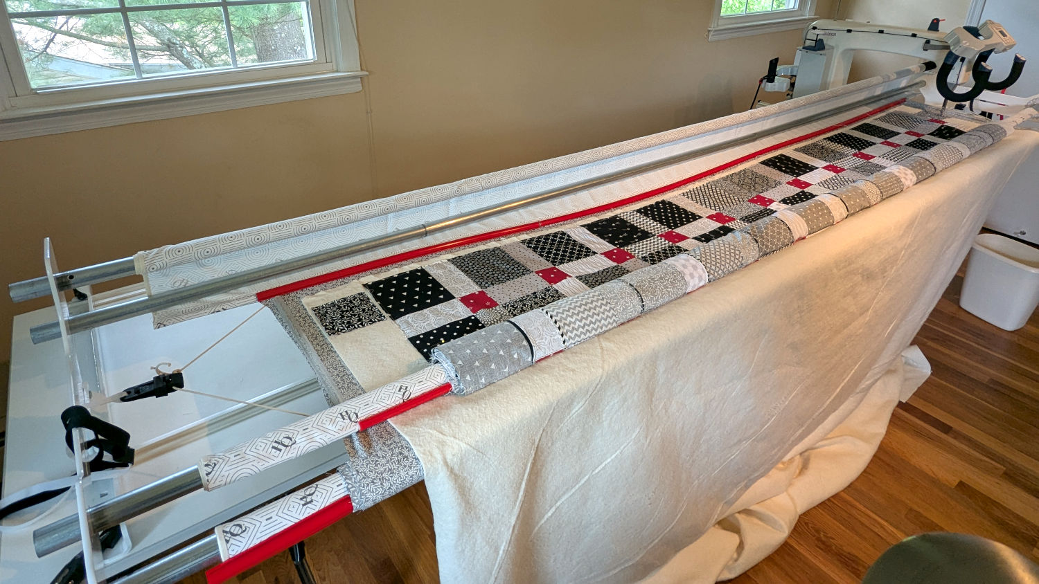
    The finished part of the quilt passes under the bottom bar on the left (the rear of the machine table) and forms an ever-increasing roll around the top bar; the white fabric leader attaches to the edge of the quilt. The LED strips illuminate the in-progress part of the quilt under the arm and should be far enough forward to not snag on the rolled-up finished part.

    I think there’s now enough light to work with:

    HQ Sixteen - under-arm lights - top view
    HQ Sixteen – under-arm lights – top view

    We recently decided the motor stall Heisenbug has vanished, perhaps due to my re-soldering the motor power supply components on the PCB. It’s hard to tell with Heisenbugs, but sometimes they decohere into a desirable state.

    After the better part of a year, Mary’s vintage HQ Sixteen runs better than new!

    A blog search unearths an extensive project in reverse chronologic order.

  • HQ Sixteen: Nose Ring Lights Power Supply

    HQ Sixteen: Nose Ring Lights Power Supply

    With the quilt off the HQ Sixteen, I could install the 24 V power supply for the Nose Ring Lights:

    HQ Sixteen Nose Ring Lights - power supply installed
    HQ Sixteen Nose Ring Lights – power supply installed

    IMO, black nylon screws look spiffier than brass.

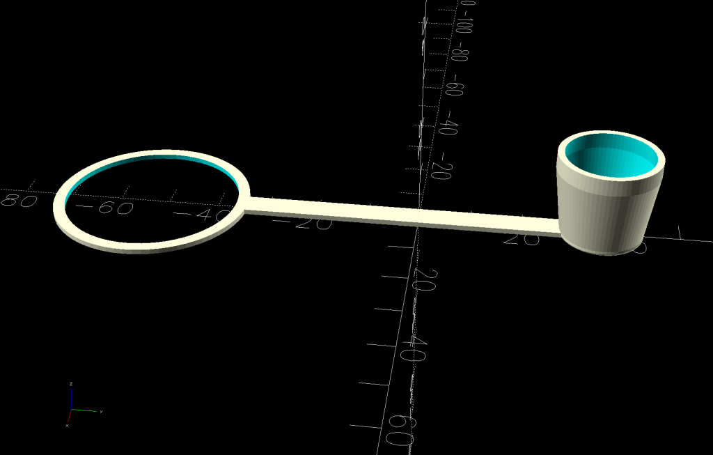
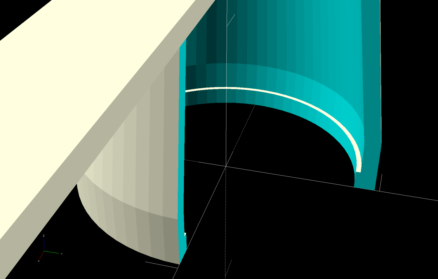
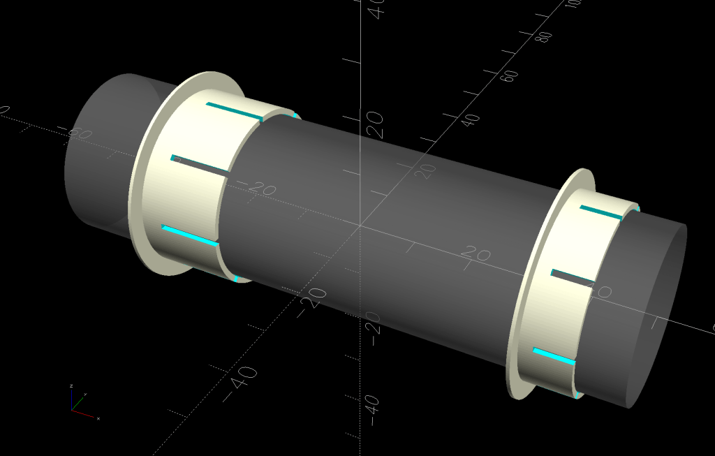
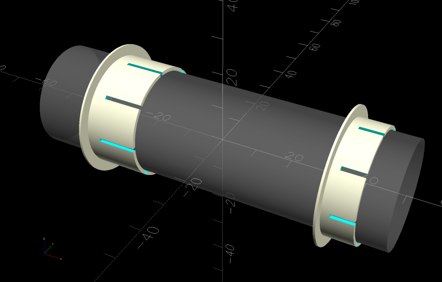
    The solid model shows the covers have a 2 mm overlap with the power supply case to keep them lined up:

    HQ Sixteen Nose Ring Lights - power supply cover - solid model
    HQ Sixteen Nose Ring Lights – power supply cover – solid model

    I managed to reuse three of the five holes from the previous 12 V power supply and drill only three more:

    HQ Sixteen Nose Ring Lights - power supply detail
    HQ Sixteen Nose Ring Lights – power supply detail

    The tops of the power supply ears aren’t quite flat, giving the standoffs a slight tilt that the covers mostly drag back into alignment.

    The M4 brass standoffs screw into holes tapped in the thick plastic, thus eliminating nuts inside the power pod:

     HQ Sixteen Nose Ring Lights - power supply wiring
    HQ Sixteen Nose Ring Lights – power supply wiring

    The yellow silicone tape wraps two pairs of Wago connectors that dramatically simplify electrical connections in anything with enough space for their chonky bodies.

    In the unlikely event you need such things, the original post links the OpenSCAD source code.

    With the power supply in place, I think I can put some LED strips under the arm of the machine to light up more of the quilt than the nose lights can reach. More pondering is in order.

  • HQ Sixteen: Nose Ring Lights

    HQ Sixteen: Nose Ring Lights

    We don’t know what the proper term might be for this part of the machine, but it looks sorta like a nose and the lights form most of a ring around it, so I’m going with “Nose Ring Lights”:

    HQ Sixteen Nose Ring lights - front view
    HQ Sixteen Nose Ring lights – front view

    The general idea is to put more light on the quilt than the Chin Light, which looked pretty good until the COB LED strip started flickering as the LEDs failed.

    Handi-Quilter sells a ring light for machines manufactured a decade later than ours, but it uses a built-in USB jack this machine lacks.

    One of two (apparently) unused M4 holes on the left side of the machine frame suggested a mounting point for a 3D printed bracket:

    HQ Sixteen Nose Ring Lights - solid model
    HQ Sixteen Nose Ring Lights – solid model

    The ramp matches the 3° (-ish) mold draft of the machine frame, which I initially ignored by angling the tab, but a tilted frame looked awful; it’s now aligned with local horizontal..

    A few iterations got all the pieces & holes in their proper places:

    HQ Sixteen Nose Ring lights - iterations
    HQ Sixteen Nose Ring lights – iterations

    The smaller (rampless) bracket has three LED strips, but a quick test showed more light would be better:

    HQ Sixteen Nose Ring lights - bottom view
    HQ Sixteen Nose Ring lights – bottom view

    The lack of a transparent-ish cover is obviously unsuitable for a commercial product, but the key design goal is to not interfere with spreading as much light as possible across as much of the quilt as possible. The black JB Weld Plastic Bonder blobs keep the 24 VDC supply out of harm’s way, which is as good as it needs to be for now.

    The bracket has three sides, because the right side of the machine has all the thread guide hardware. Putting anything over there seemed likely to interfere with either thread movement or fingers making adjustments.

    Fortunately, the wider bracket doesn’t stick out too far beyond the machine frame and the doubled LED strips create a much smoother light pool:

    HQ Sixteen Nose Ring lights - left front view
    HQ Sixteen Nose Ring lights – left front view

    Yes, the quilt is focused and the LED frame is blurred.

    The larger light-emitting area reduces the shadow under the left rod (supporting the ruler foot) enough to be unobjectionable.

    A 0.2 mm layer thickness transforms the smooth ramp into stair steps:

    HQ Sixteen Nose Ring Lights - PrusaSlicer
    HQ Sixteen Nose Ring Lights – PrusaSlicer

    They’re inconspicuous after the bracket is installed.

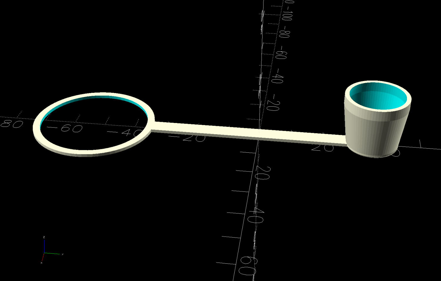
    The Chin Light ran on 12 V and these strips require 24 V, so the OpenSCAD code creates a pair of endcaps for the new supply, which is of course completely different than the old supply. Setting that up must await quilt completion.

    The OpenSCAD source code as a GitHub Gist:

    // HQ Sixteen Nose Ring Lights
    // Ed Nisley – KE4ZNU
    // 2025-05-23
    include <BOSL2/std.scad>
    Layout = "Show"; // [Show,Build,NosePlan,PowerCap]
    // Number of side-by-side LED strips
    Strips = 2;
    /* [Hidden] */
    HoleWindage = 0.2;
    Protrusion = 0.1;
    NumSides = 3*3*4;
    $fn=NumSides;
    ID = 0;
    OD = 1;
    LENGTH = 2;
    Gap = 5.0;
    WallThick = 5.0; // default thickness for things
    NoseRadius = 6.0; // corner roundoff
    NoseOA = [44.0,36.5]; // overall nose size
    NoseAngles = [87,87]; // front & rear inward angles wrt left side
    NoseCenters = [ // centers of circles defining the nose corners
    [NoseRadius, NoseOA.y/2 – NoseRadius],
    [NoseRadius,-(NoseOA.y/2 – NoseRadius)],
    [NoseOA.x – NoseRadius, NoseOA.y/2 – NoseRadius – (NoseOA.x – 2*NoseRadius)*tan(90 – NoseAngles[0])],
    [NoseOA.x – NoseRadius,-(NoseOA.y/2 – NoseRadius – (NoseOA.x – 2*NoseRadius)*tan(90 – NoseAngles[1]))],
    ];
    LEDMargin = 1.0;
    LEDStrip = [41.5 + LEDMargin,8.0 + LEDMargin,1.8 + 0.2]; // 24 V COB LED strip unit + windage
    LEDBaseOA = [LEDStrip.x + Strips*LEDStrip.y,NoseOA.y + 2*Strips*LEDStrip.y,WallThick]; // LED mount
    DraftAngle = 3.0; // angle of frame wrt horizontal at right end of nose
    DraftWedge = [NoseOA.x,NoseOA.y + 2*LEDStrip.y,NoseOA.x*tan(DraftAngle)];
    HoleOffset = [-10.0,5.5,DraftWedge.z + 10.0]; // from left front corner of nose
    HolePosition = HoleOffset + [0,-NoseOA.y/2,WallThick]; // absolute coordinates from origin
    Screw = [4.0 + HoleWindage,9.0,2.0]; // LENGTH=button head
    Bracket = [WallThick,Screw[OD] + 4.0,HoleOffset.z + Screw[OD/2] + 2.0 + WallThick];
    Supply = [46.0,30.0,21.0]; // 24 VDC power supply
    SupplyScrewOffset = 5.0; // … M4 screw hole from end of supply case
    CapWall = 3.0;
    CapRadius = CapWall – 1.0;
    CapInset = 1.0;
    CapOA = [20.0,Supply.y + 2*CapWall,Supply.z + CapWall]; // x & y to cover existing holes
    //———-
    // Define Shapes
    //—– 2D outline of nose piece just under frame casting
    module NosePlan() {
    hull()
    for (p = NoseCenters)
    translate(p) circle(r=NoseRadius);
    }
    //—– LED mounting plate
    module Mount() {
    union() {
    difference() {
    union() {
    right(LEDBaseOA.x/2 – Strips*LEDStrip.y)
    cuboid(LEDBaseOA,rounding=WallThick/2,except=BOTTOM,anchor=BOTTOM);
    up(LEDBaseOA.z) left(-HoleOffset.x/2)
    yrot(DraftAngle)
    cuboid(DraftWedge,rounding=WallThick/2,edges="Z",anchor=LEFT+BOTTOM);
    }
    down(Protrusion)
    linear_extrude(LEDBaseOA.z + DraftWedge.z + Protrusion)
    NosePlan();
    if (Strips > 1)
    translate([HolePosition.x – Bracket.x/2,HolePosition.y – Bracket.y,-Protrusion])
    cyl(LEDBaseOA.z + 2*Protrusion,d=4.0,anchor=BOTTOM);
    }
    difference() {
    union() {
    translate([HolePosition.x,HolePosition.y,(Bracket.x/2)*sin(DraftAngle)])
    left(Bracket.x)
    cuboid(Bracket,rounding=WallThick/2,edges=LEFT,anchor=BOTTOM+LEFT);
    translate([HolePosition.x – Bracket.x/2,HolePosition.y,0]) // rounding filler
    cuboid([LEDStrip.y,Bracket.y,WallThick],anchor=BOTTOM+LEFT);
    }
    translate(HolePosition)
    xrot(180/6) xcyl(l=NoseOA.x,d=Screw[ID],$fn=6);
    }
    }
    }
    //—– Endcap for power supply
    module EndCap() {
    difference() {
    cuboid(CapOA,rounding=CapRadius,except=BOTTOM,anchor=LEFT+BOTTOM);
    right(CapOA.x – CapWall) down(Protrusion)
    cuboid(Supply + [0,0,Protrusion],anchor=RIGHT+BOTTOM);
    right(CapInset + SupplyScrewOffset)
    zcyl(l=2*CapOA.z,d=Screw[ID],$fn=6,anchor=BOTTOM);
    }
    }
    //———-
    // Build things
    if (Layout == "NosePlan") {
    NosePlan();
    }
    if (Layout == "PowerCap") {
    EndCap();
    }
    if (Layout == "Show") {
    Mount();
    ctr = 80;
    ofs = Supply.x/2 – CapInset;
    left(ctr – ofs)
    EndCap();
    left(ctr + ofs)
    xflip()
    EndCap();
    color("Silver",0.6)
    left (ctr)
    cuboid(Supply,anchor=BOTTOM);
    }
    if (Layout == "Build") {
    Mount();
    back((LEDBaseOA.y + CapOA.y)/2 + Gap) right(Gap) up(CapOA.z) zflip()
    EndCap();
    back((LEDBaseOA.y + CapOA.y)/2 + Gap) left(Gap) zrot(180) up(CapOA.z) zflip()
    EndCap();
    }

  • HQ Sixteen: Chin Light Failure

    HQ Sixteen: Chin Light Failure

    The COB LED module I stuck under the HQ Sixteen’s chin worked well at first:

    HQ Sixteen Chin Light - results
    HQ Sixteen Chin Light – results

    Last month it began to flicker and I eventually caught it in the act:

    HQ Sixteen Chin Light - first failure
    HQ Sixteen Chin Light – first failure

    That’s taken with the phone’s selfie camera from the quilt’s viewpoint, which is much too close for the camera’s focus, but you get the general idea.

    Pulling it off, putting it on the bench, applying 12 V, and letting it heat up produced this:

    HQ Sixteen Chin Light - hot failure
    HQ Sixteen Chin Light – hot failure

    That’s with the voltage backed off to 8 V to avoid burning out the exposure.

    Letting it cool a bit:

    HQ Sixteen Chin Light - cool failure
    HQ Sixteen Chin Light – cool failure

    You may recall I stuck the aluminum backing plate to the HQ Sixteen’s case aluminum body with some heatsink tape and the thing ran just warm to the touch, so I suspect the initial failure had little-or-nothing to do with overheating and a lot to do with buying stuff from eBay.

    That suspicion is supported by having two more of those in the drawer with their failed chips circled.

    So a better design is in order …

  • HQ Sixteen: Custom Small-arc Quilting Ruler

    HQ Sixteen: Custom Small-arc Quilting Ruler

    For reasons not relevant here, Mary is completing a friend’s quilt for the family. Part of the existing design involves stitching arcs around each side of a myriad small blocks across the quilt:

    Small arc quilting ruler - block border
    Small arc quilting ruler – block border

    After free-motion quilting a few blocks, Mary decided the peak of the curve looked good at ⅜ inch from the block edge. This sort of thing is generally done by “ruler quilting” with the machine’s foot guided by a ruler, but none of her considerable assortment of quilting rulers had exactly the arc required for that curve.

    The stitch path will be ¼ inch away from the edge of the ruler, as set by the ½ inch OD Handi-Feet Sure Foot centered on the needle:

    HQ Sixteen Handi-feet conversion - Sure-foot installed
    HQ Sixteen Handi-feet conversion – Sure-foot installed

    Knowing the blocks are 2-¼ inch on a side and the arc is ⅜ inch tall, the Chord Equation gives the 1-⅞ inch radius of the circle matching the arc. Using proper terminology:

    With those numbers in hand, producing a suitable quilting ruler is straightforward:

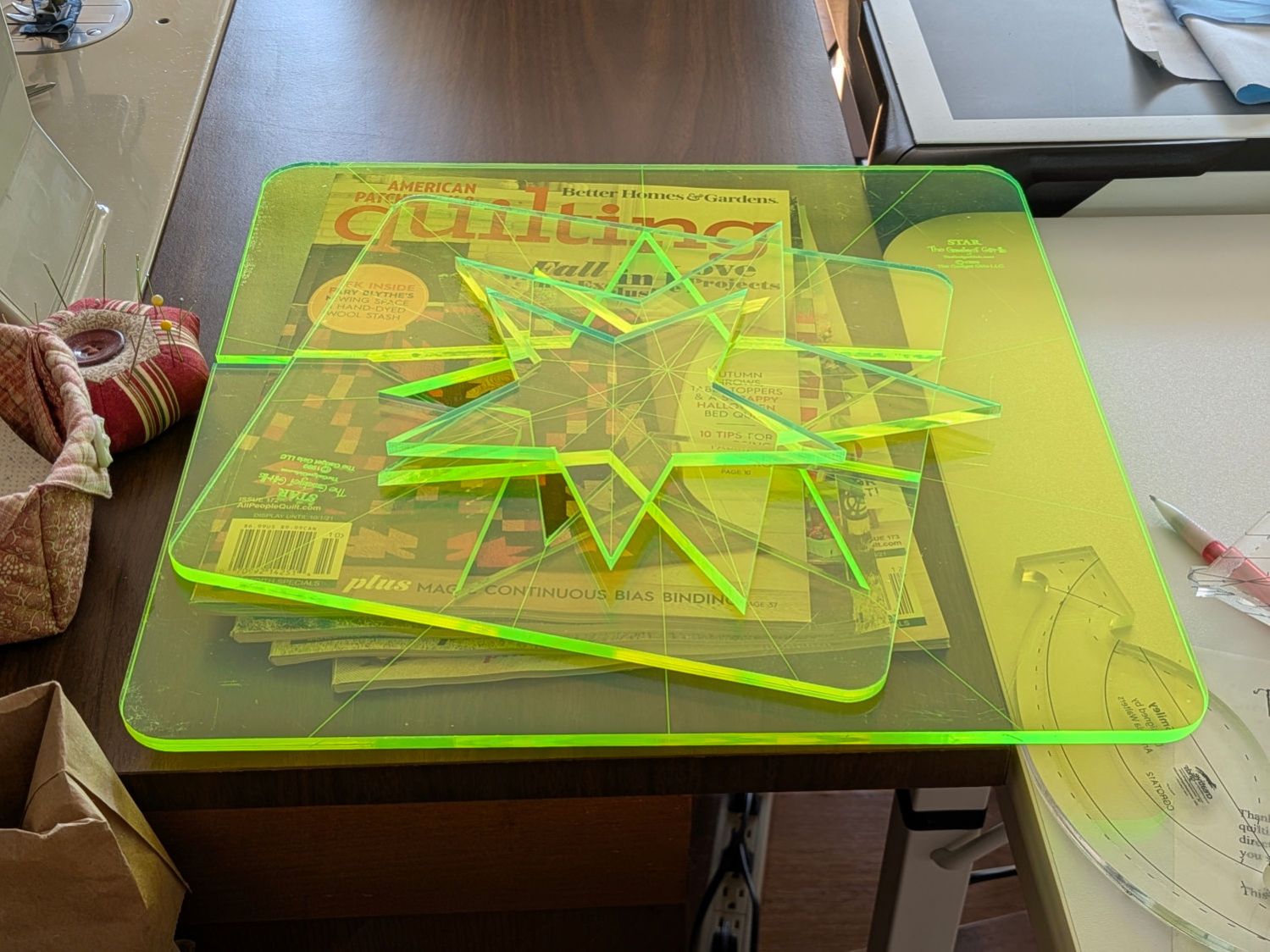
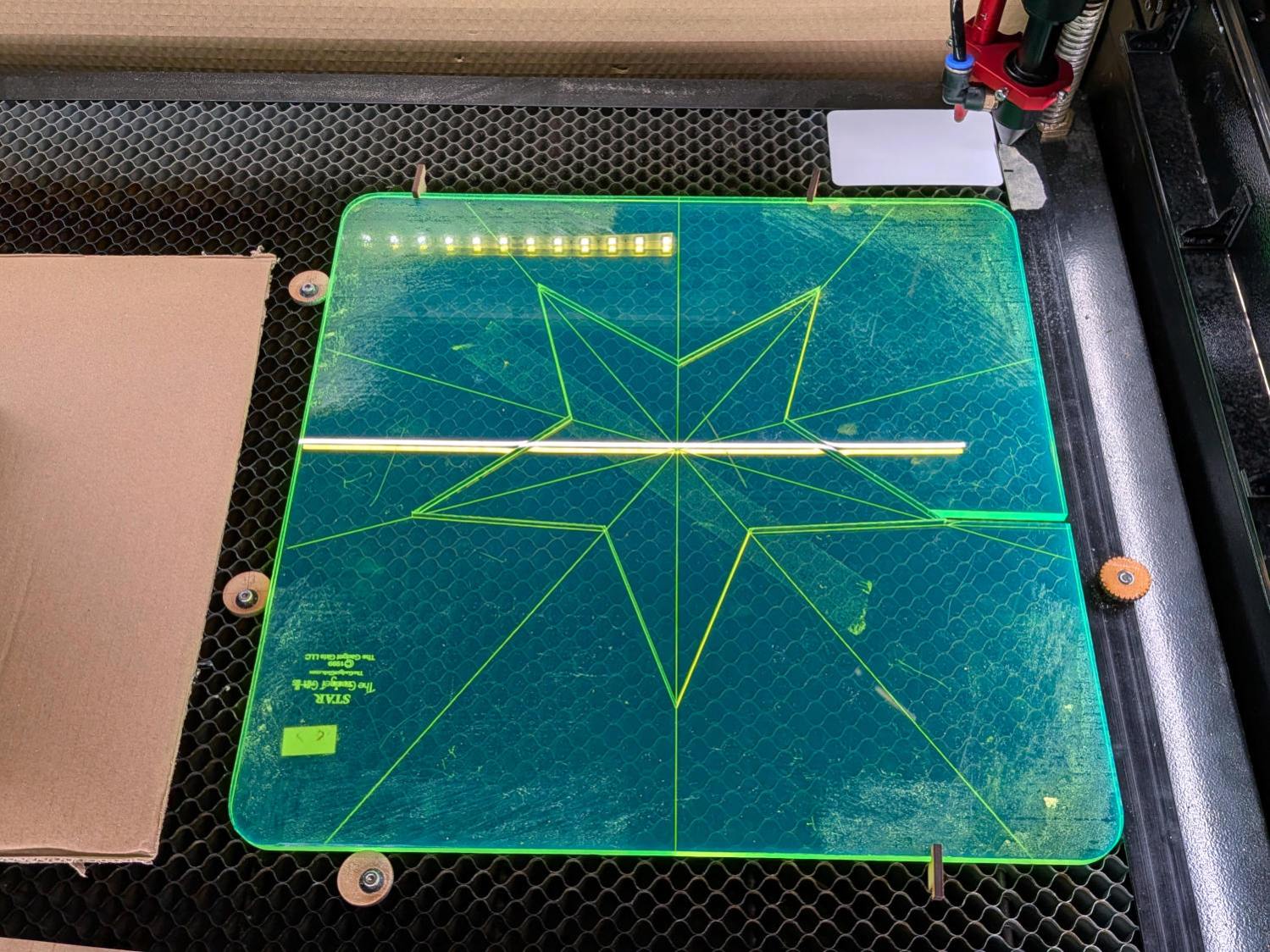
    Judy Quilt - small arcs - LightBurn layout
    Judy Quilt – small arcs – LightBurn layout

    The legends are backwards, because the lines must be engraved on the bottom of the ruler to eliminate parallax through the ¼ inch acrylic sheet:

    Small arc quilting ruler - alignment
    Small arc quilting ruler – alignment

    She can now eyeballometrically align the engraved square with the edges of the block to put the curved edge at the right place to guide the foot:

    Small arc quilting ruler - stitch line
    Small arc quilting ruler – stitch line

    After half a dozen blocks, she reports the ruler works as intended and the duplicated Start / Stop buttons on the improved hand grips let her control the machine with either thumb. She uses Stitch Regulator mode to produce a uniform line of stitches regardless of speed variations around the arc.

    Now she can finish the quilt and have all those curves look the way she wants.

    I knew that laser cutter would come in handy …

  • HQ Sixteen: Improved Control Cap Wiring

    HQ Sixteen: Improved Control Cap Wiring

    The new control caps on the HQ Sixteen’s handlebars have three switches apiece:

    HQ Sixteen - grip cap installed - left
    HQ Sixteen – grip cap installed – left

    A six-conductor ribbon cable brings those switch terminal through the handlebars, across the smaller PCBs where the original switches plugged in, and atop the main PCB behind / under the LCD panel where they get wired together:

    HQ Sixteen - Control Button switch cable
    HQ Sixteen – Control Button switch cable

    The gray ribbon cable carries power for the LEDs and returns the original switch signals formerly plugged into one of the four-pin headers on the right PCB. The same PCB is used on the other side and the switches over there plug into the other header.

    The central PCB is also used for the rear handlebars, which do not have the smaller PCBs, and those switch cables plug directly into four-pin headers mounted instead of the headers for the gray ribbon cables:

    HQ Sixteen - Control Button central PCB
    HQ Sixteen – Control Button central PCB

    Some probing and doodling produced a diagram of the switch connections:

    HQ Sixteen - Control Button Wiring
    HQ Sixteen – Control Button Wiring

    Working with the handlebars either inverted or flipped left-for-right on the workbench makes this far more confusing than it really should be.

    In any event, the bottom diagram shows the connections between the two four-pad header positions on the central PCB and the two six-pin headers for the new switches. I used a 2×6 pin header block to plug in the new switches, connected the pins with soldered Wire-Wrap wire, and used three-wire ribbon cable to the PCB pads.

    The general idea was to duplicate the Start-Stop and Needle Up/Down switches on both sides, while maintaining the same relative positions of the Fast / Slow switches. In effect, the two new switches on each side are wired in parallel to the original switch pads on the PCB.

    Surprisingly, I got the three-wire ribbon cables from the four-pad headers right on the second try, which involved flipping it over. The top and bottom pads on those headers are connected together, so the three-wire cable can go on either way to reverse the positions of the other two wires.

    And then the new switches Just Worked™ … whew!