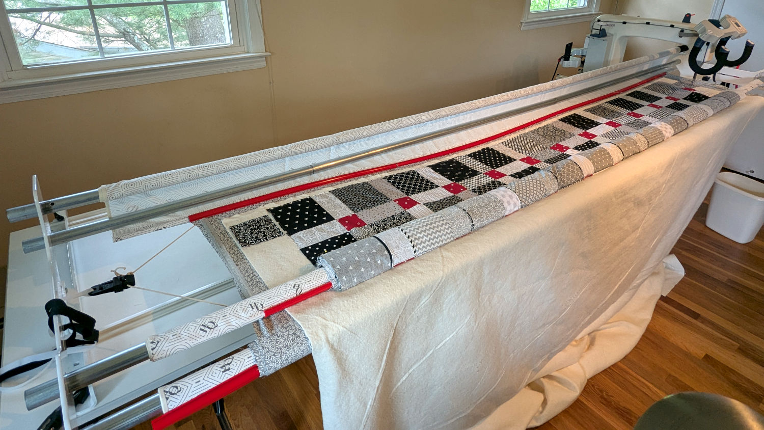
Mary made a frame weight to maintain tension on the fabric in the HQ Sixteen longarm:
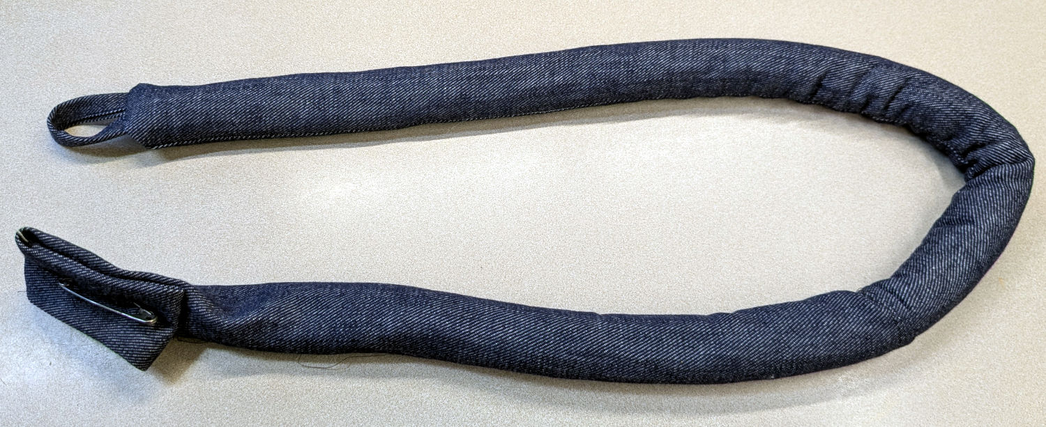
It’s a sturdy cloth tube filled with BBs, somewhat like a grossly overweight door snake (a.k.a. draft stopper).
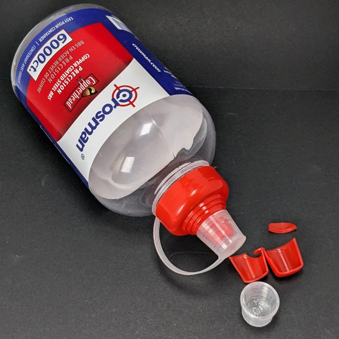
The bottle of 6000 copper-plated steel BBs arrived in an overwrap bag of the sort Amazon applies to all bottled products. This was a Good Thing, because the scrap of packing paper did nothing to cushion the bottle in an otherwise empty box. The bag contained most of the shattered cap and a few BBs, with escapees rattling around inside the box and surely a few left along the way.
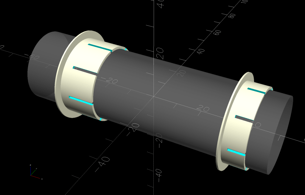
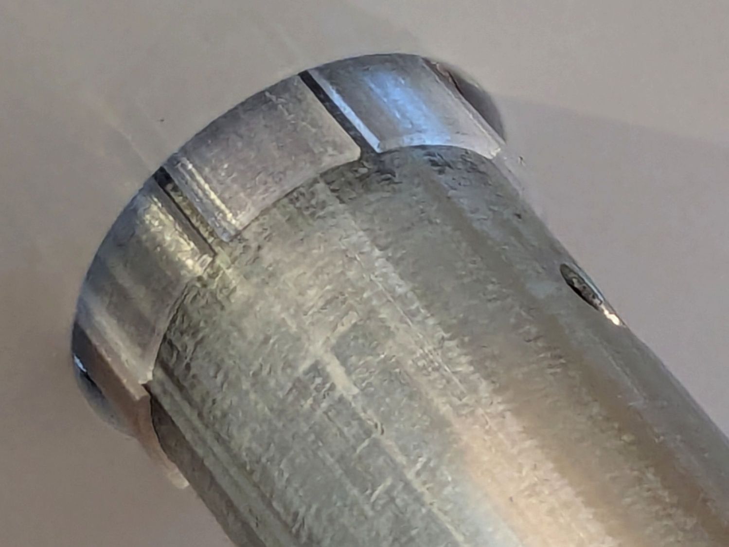
So I conjured a replacement cap from TPU:
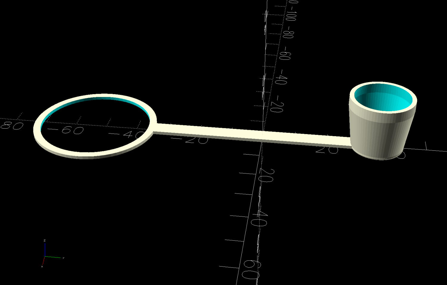
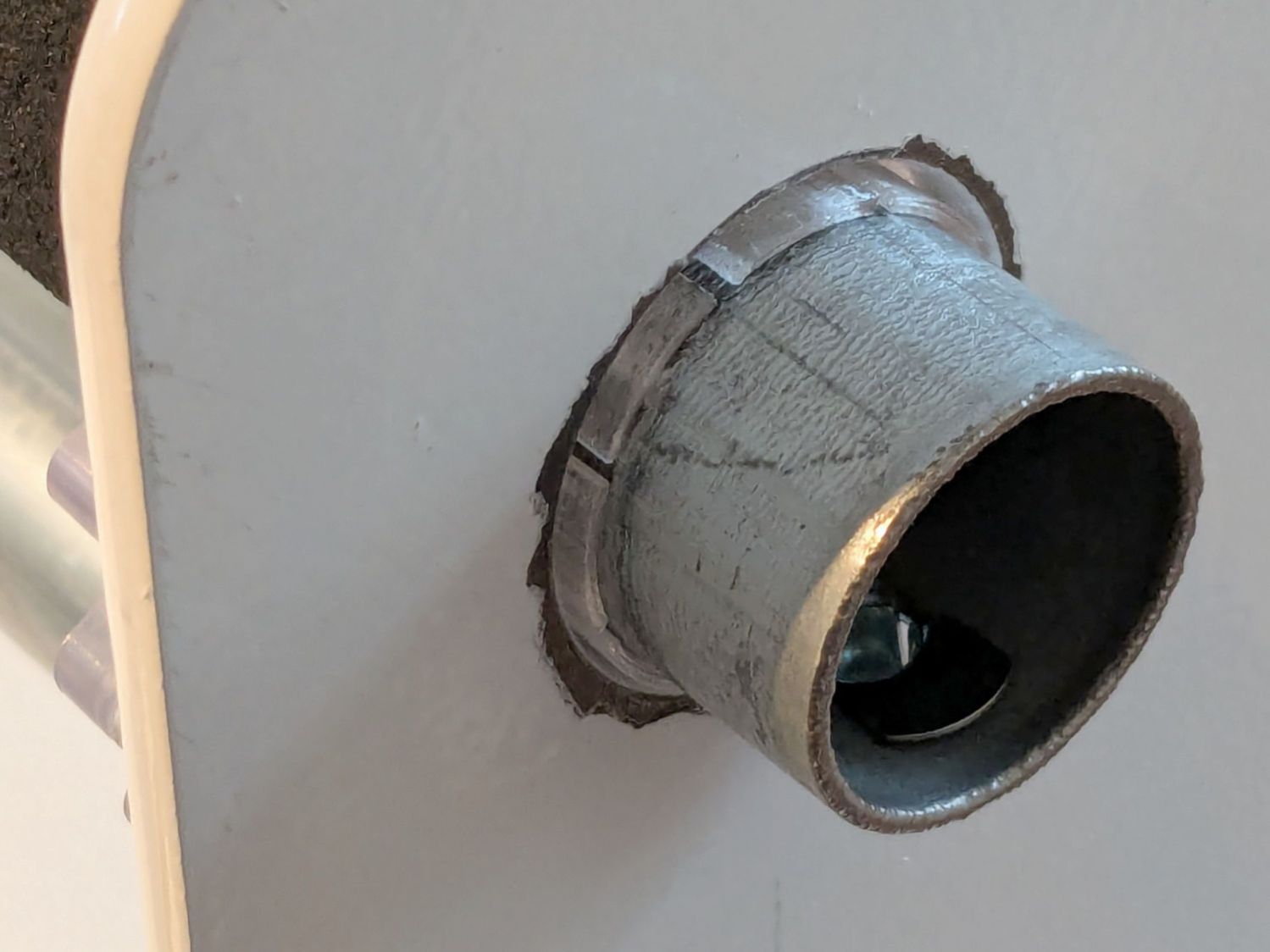
It fits around the bottle neck and snaps onto the spout just like the original:
Except this one is unbreakable.
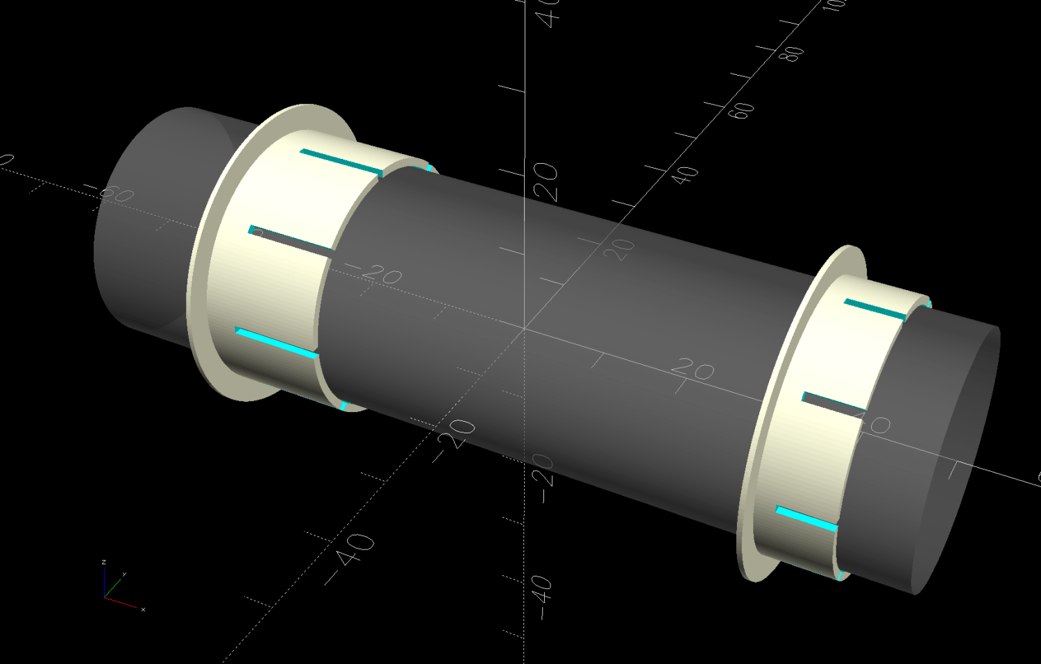
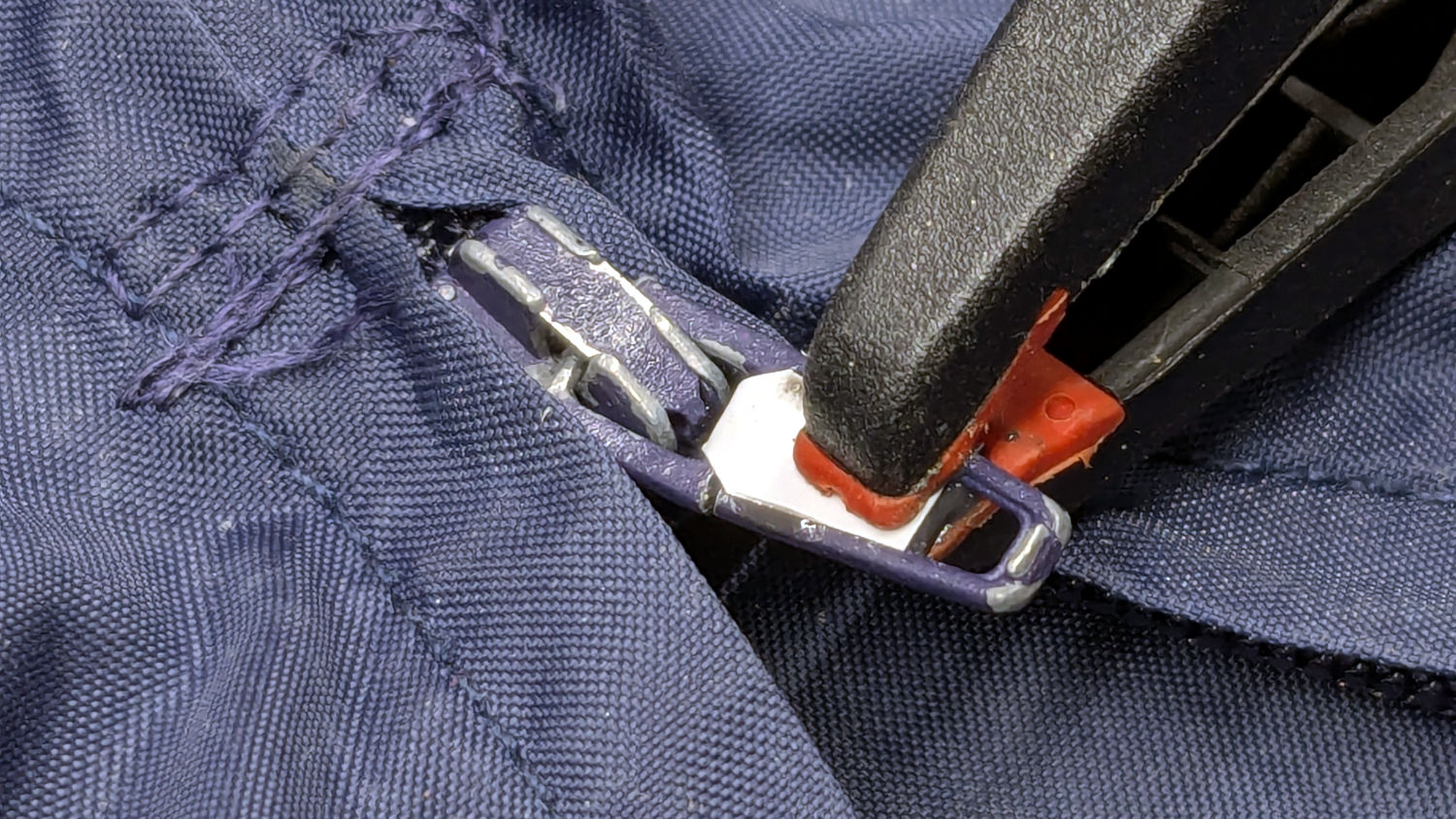
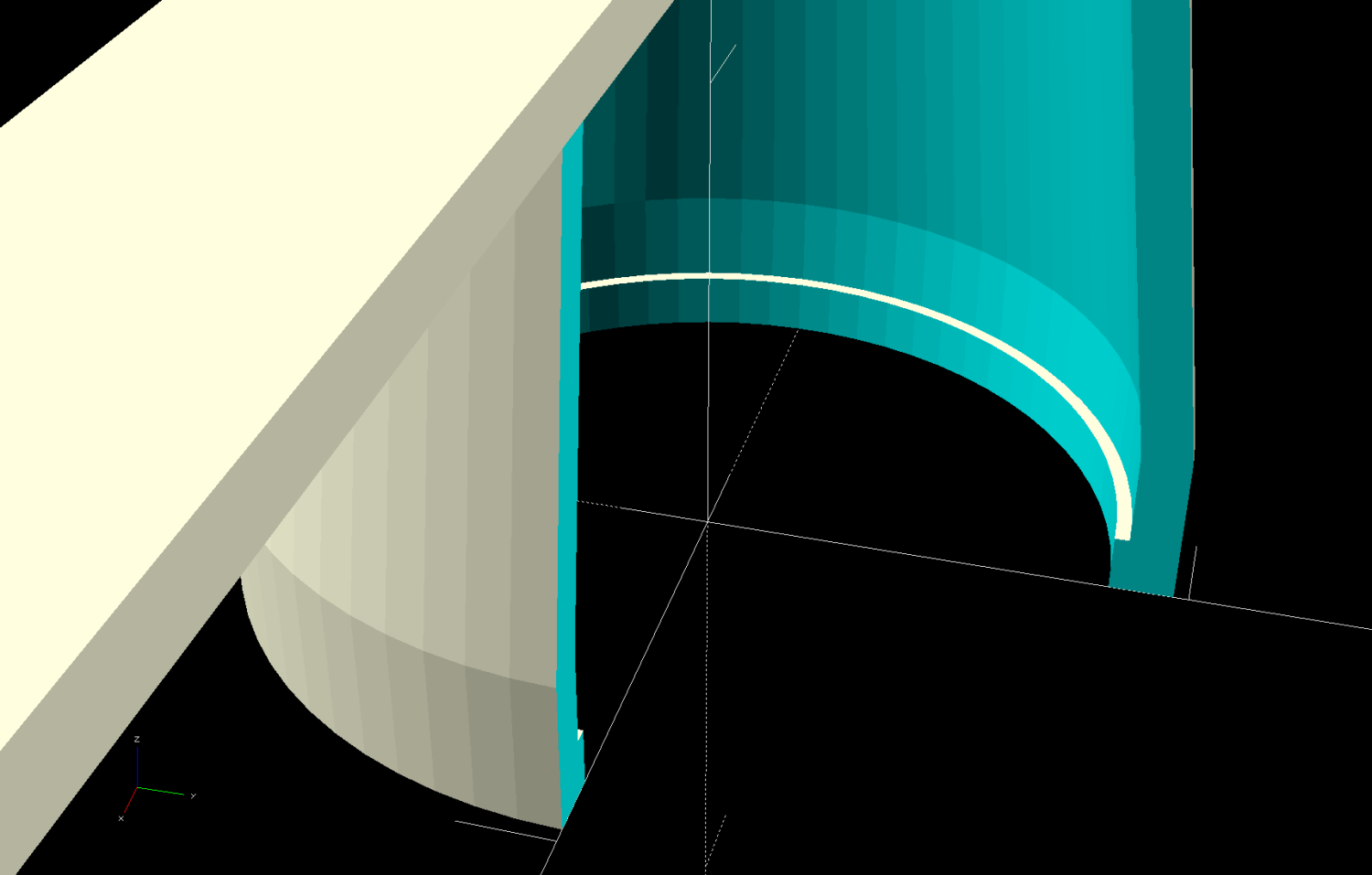
The strapless TPU cap was a quick test to verify the fiddly shoulder snapping onto the bottle snout:
As it turned out, we poured all 6000 BBs (minus those few lost-in-transit strays) into the cloth tube, but the bottle will come in handy for something someday.
The OpenSCAD source code as a GitHub Gist:
| // Crosman BB bottle cap | |
| // Ed Nisley – KE4ZNU | |
| // 2026-02-22 | |
| include <BOSL2/std.scad> | |
| Layout = "Show"; // [Show,Build,Section] | |
| /* [Hidden] */ | |
| ID = 0; | |
| OD = 1; | |
| LENGTH = 2; | |
| HoleWindage = 0.2; | |
| Protrusion = 0.1; | |
| NumSides = 6*3*4; | |
| $fn=NumSides; | |
| WallThick = 1.0; | |
| Heights = [1.2,2.0,13.0,WallThick]; // for easy tweaking | |
| Ring = [34.5,39,WallThick]; | |
| Strap = [70.0,5.0,Ring[LENGTH]]; | |
| CapOAL = sum(Heights); | |
| //—– | |
| // Conjure it with magic numbers | |
| module Cap() { | |
| tube(Heights[0],id=16.8,wall=WallThick+0.6/2,anchor=BOTTOM) position(TOP) | |
| tube(Heights[1],id=17.4,wall=WallThick,anchor=BOTTOM) position(TOP) | |
| tube(Heights[2],id1=17.4,id2=14.0,wall=WallThick,anchor=BOTTOM) position(TOP) | |
| cyl(Heights[3],d=14.0+2*WallThick,rounding2=WallThick/2,anchor=BOTTOM) position(BOTTOM) | |
| cuboid(Strap,anchor=BOTTOM+LEFT) position(BOTTOM+RIGHT) | |
| left(1.0) | |
| tube(Ring[LENGTH],id=Ring[ID],od=Ring[OD],anchor=BOTTOM+LEFT); | |
| } | |
| //—– | |
| // Build things | |
| if (Layout == "Show") { | |
| Cap(); | |
| } | |
| if (Layout == "Section") { | |
| difference() { | |
| Cap(); | |
| down(Protrusion) | |
| cuboid(2*Strap.x,anchor=BOTTOM+LEFT+FRONT); | |
| } | |
| } | |
| if (Layout == "Build") { | |
| back(Strap.x/2) | |
| zrot(90) | |
| up(CapOAL) | |
| yrot(180) | |
| Cap(); | |
| } |