The Smell of Molten Projects in the Morning

Ed Nisley's Blog: Shop notes, electronics, firmware, machinery, 3D printing, laser cuttery, and curiosities. Contents: 100% human thinking, 0% AI slop.

Tag: Sewing

Fabric arts and machines

  • HQ Sixteen: Stylus Laser Ball Mount

    HQ Sixteen: Stylus Laser Ball Mount

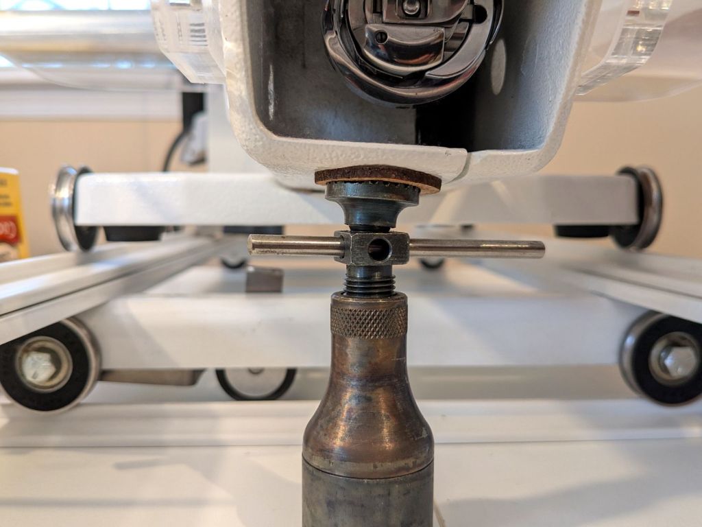
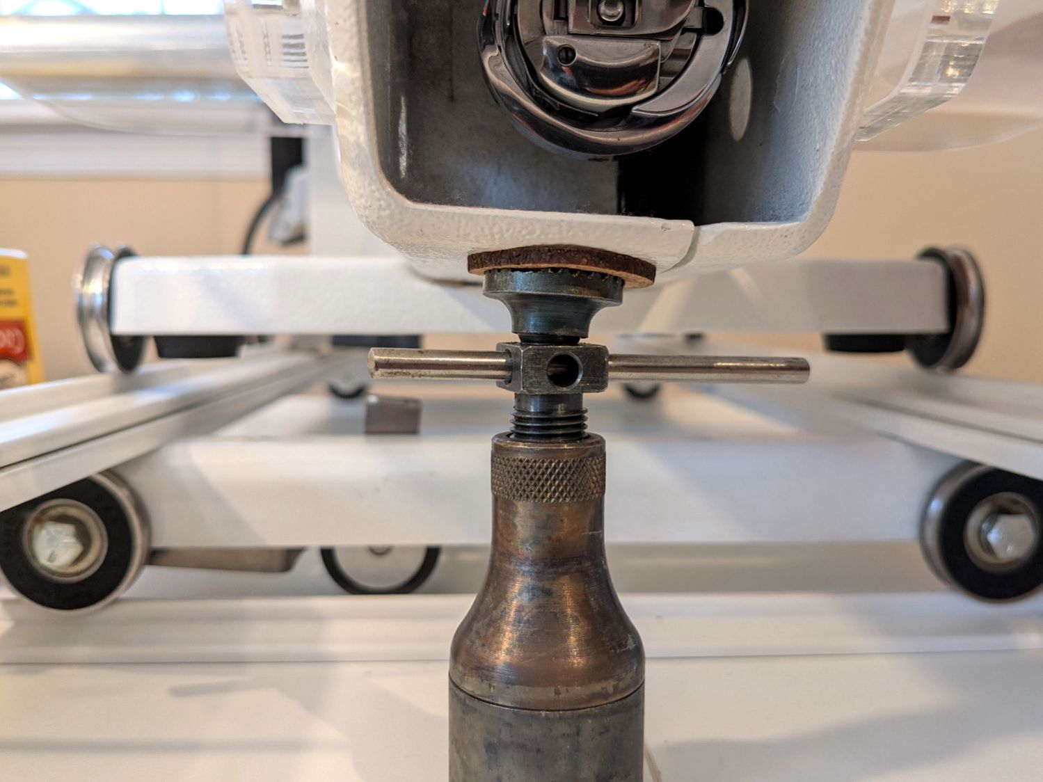
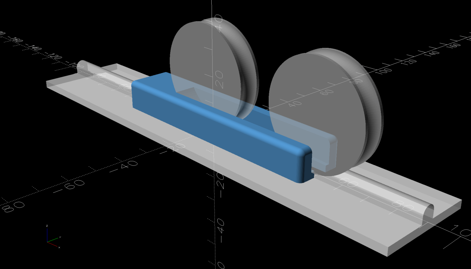
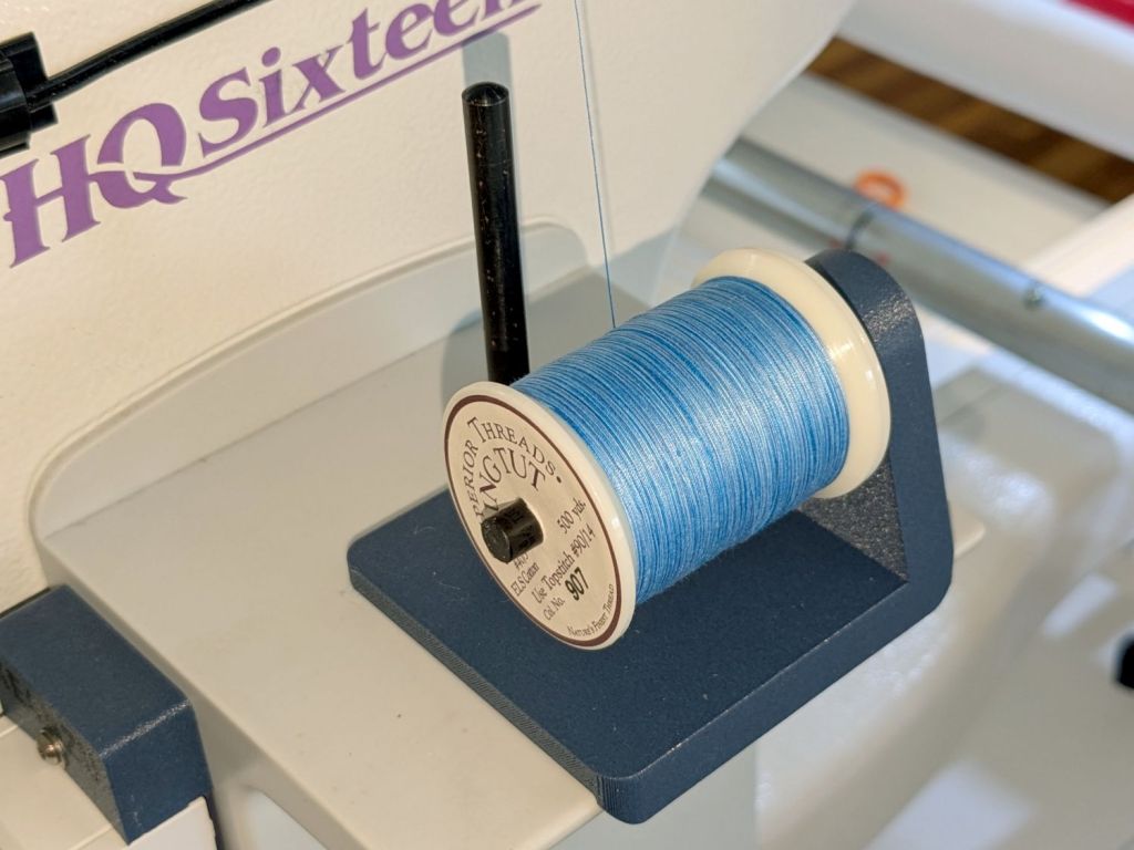
    My version of a mount for the HQ Sixteen’s “stylus laser” clamps a 1 inch polypropylene ball between two plates:

    HQ Sixteen - Stylus Laser - ball clamp test fit
    HQ Sixteen – Stylus Laser – ball clamp test fit

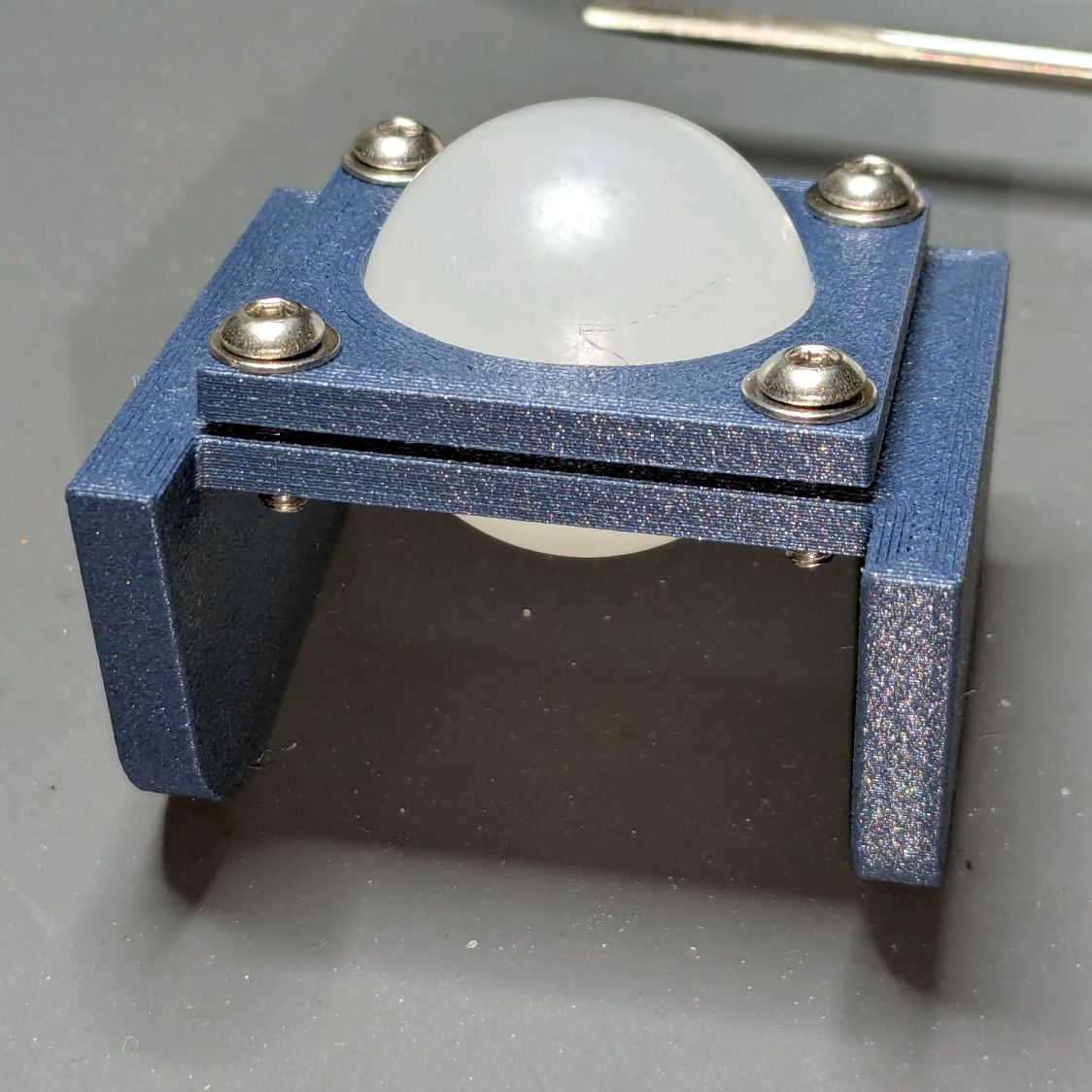
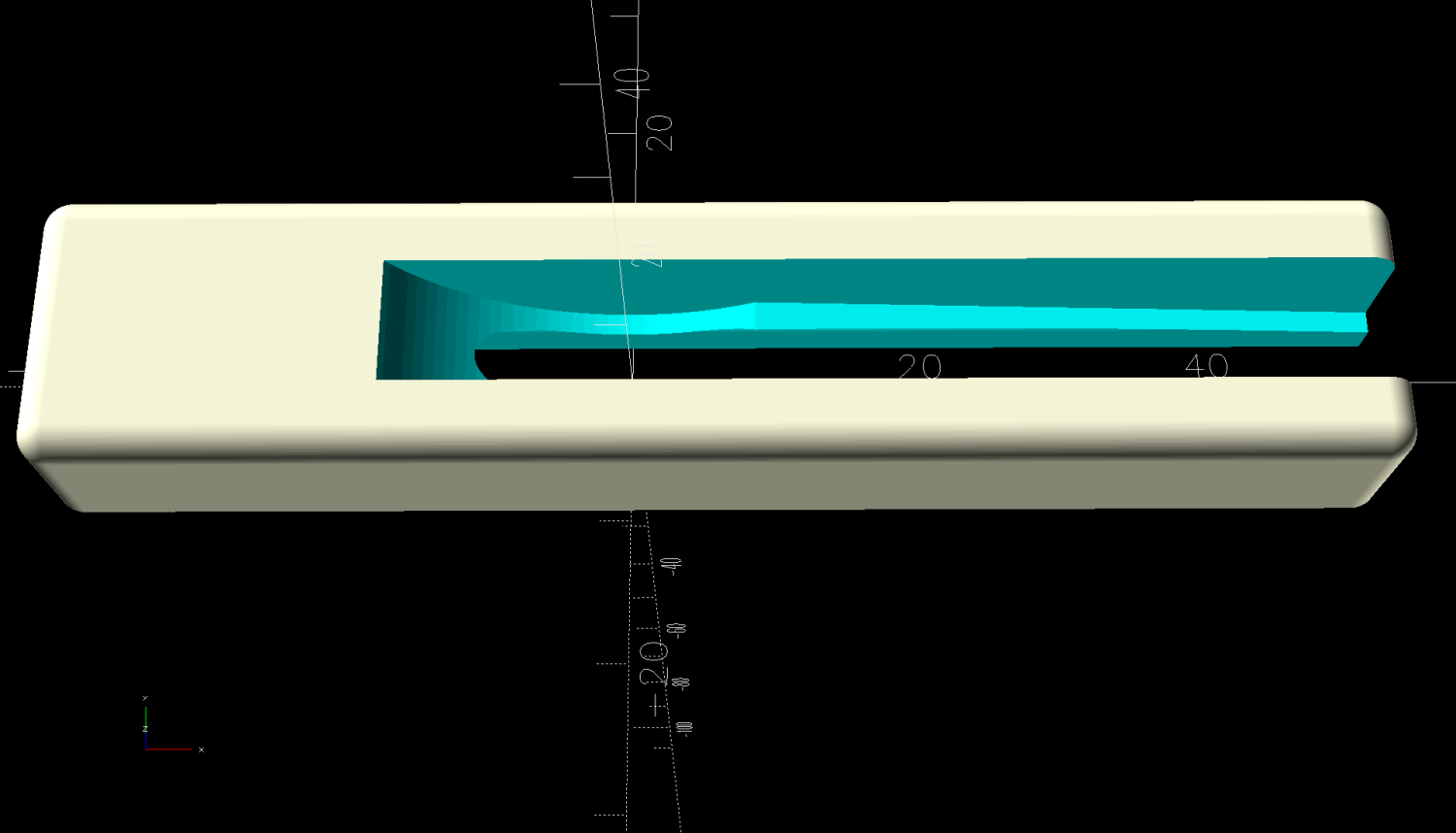
    The plates have a sphere subtracted from them and a kerf sliced across the sphere’s equator for clamping room:

    HQ Sixteen - Stylus Laser Mount - solid model
    HQ Sixteen – Stylus Laser Mount – solid model

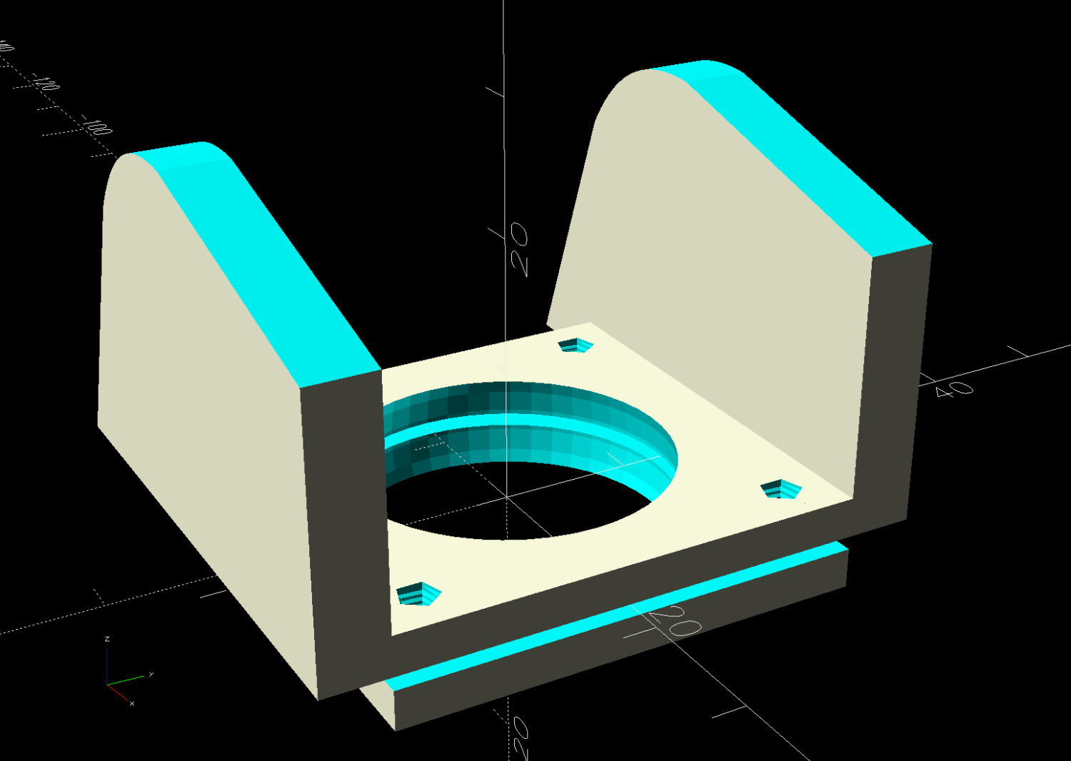
    Given that this is a relatively low-stress situation, I embedded BOSL2 nuts to produce threads in the plate rather than use brass inserts.

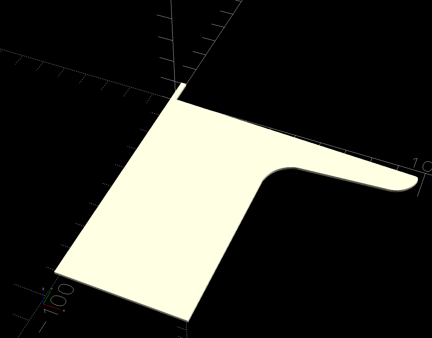
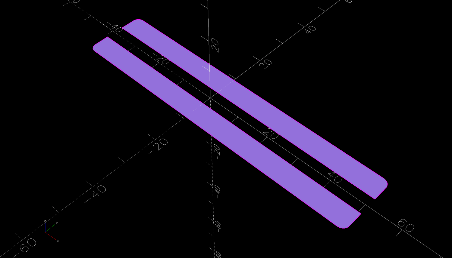
    The side plates start as simple rectangles:

    HQ Sixteen - Stylus Laser Mount - solid model - mount sides
    HQ Sixteen – Stylus Laser Mount – solid model – mount sides

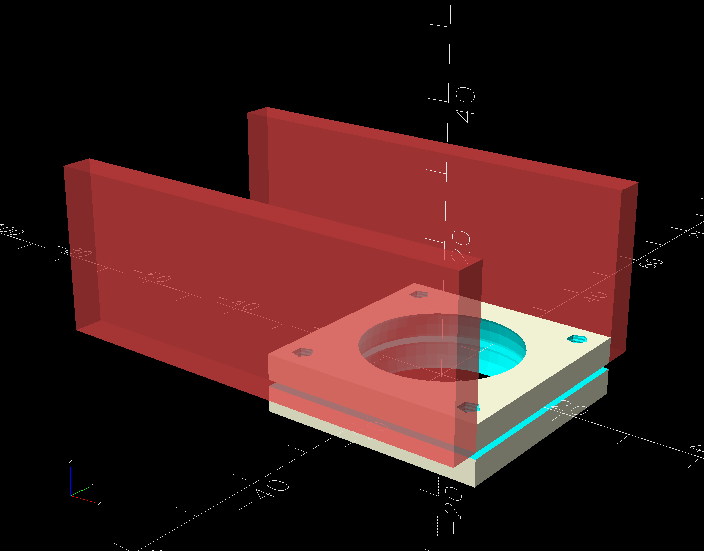
    Subtracting the electronics pod shape from those slabs matches them exactly to the curvalicious corner:

    HQ Sixteen - Stylus Laser Mount - solid model - mount shaping
    HQ Sixteen – Stylus Laser Mount – solid model – mount shaping

    The weird angle comes from tilting the mount to aim the laser in roughly the right direction when perpendicular to the plates:

    HQ Sixteen - Stylus Laser Mount - solid model - show
    HQ Sixteen – Stylus Laser Mount – solid model – show

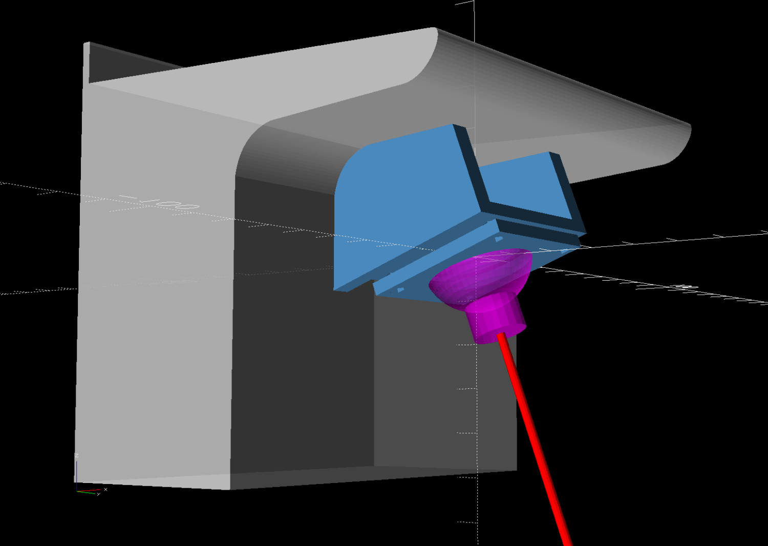
    That angle can be 0° to 30°, although 25° seems about right. The slab sides neither stick out the top nor leave gaps in the corner over that range, after some cut-and-try tinkering sizing.

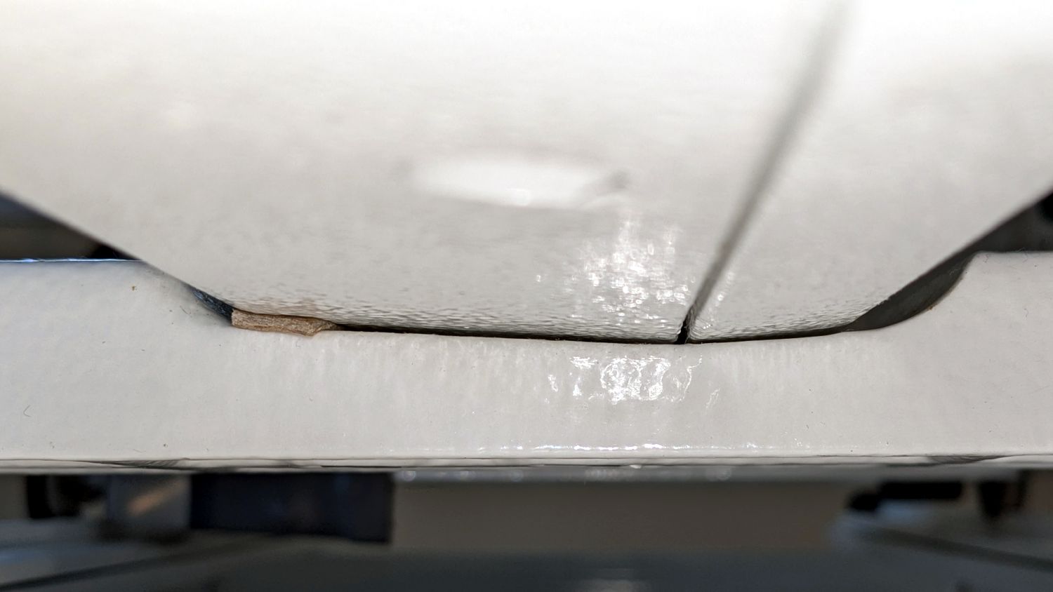
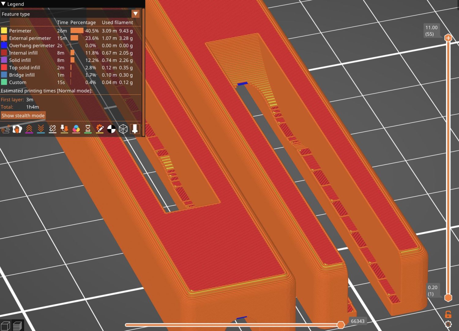
    One of the M3 screws just did not want to go into its hole:

    HQ Sixteen - Stylus Laser - threadless M3 screw
    HQ Sixteen – Stylus Laser – threadless M3 screw

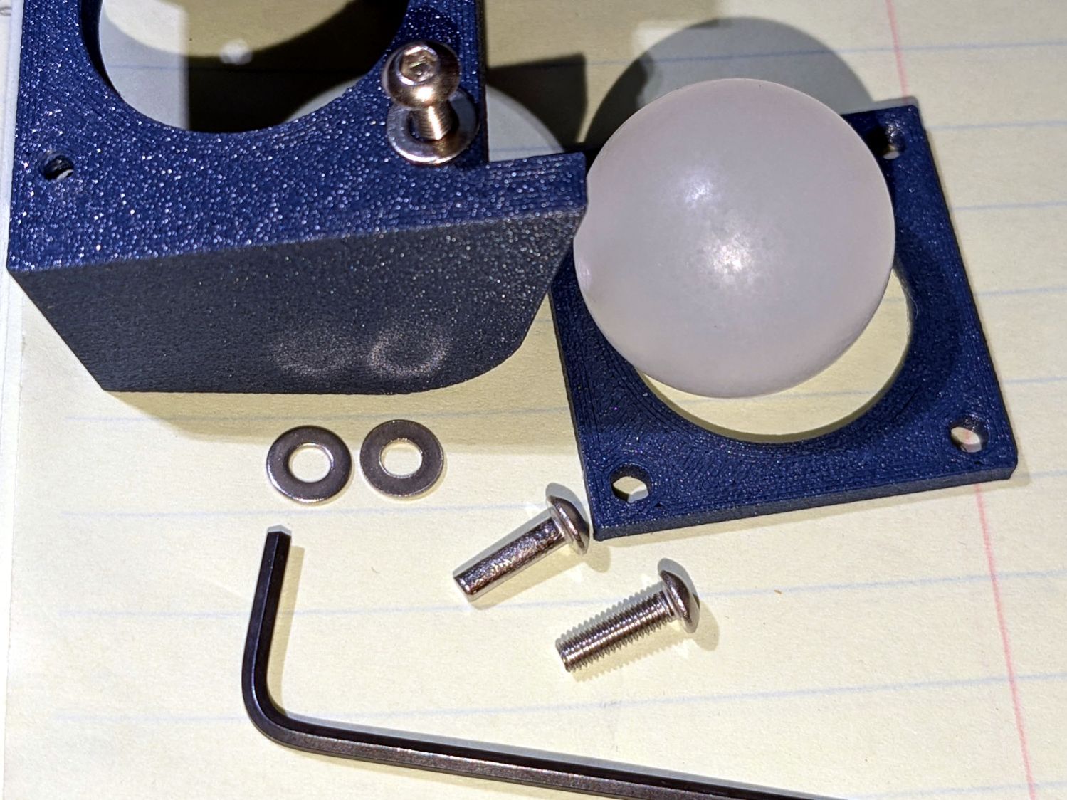
    A bad day in the screw factory, I suppose.

    The OpenSCAD source code as a GitHub Gist:

    // Handiquilter HQ Sixteen Stylus Laser Mount
    // Ed Nisley – KE4ZNU
    // 2025-02-23
    include <BOSL2/std.scad>
    include <BOSL2/threading.scad>
    Layout = "Pod"; // [Show,Build,Pod,Mount]
    /* [Hidden] */
    PodWidth = 110.0; // overall width of pod
    PodScrewClear = 50.0; // clear distance between pod screws
    PodRecenter = [0,0]; // pod trace upper corner to origin if not done in Inkscape
    BaseAngle = -25; // laser neutral angle
    BallOD = 25.4 + 0.2; // bearing ball + easy fit clearance
    BallOffset = [70.0,0,-35.0]; // upper corner to ball center
    LaserOD = 12.2; // laser module
    LaserLength = 38.0;
    Kerf = 1.0; // clamp gap
    Plate = [35.0,35.0,8.0 + Kerf]; // basic mount plate
    WallThick = 5.0; // upright walls: plate to pod
    WasherOD = 7.0;
    ScrewPitch = 0.5;
    ScrewNomOD = 3.0;
    ScrewNomID = ScrewNomOD – ScrewPitch;
    ScrewOC = Plate – [WasherOD,WasherOD,0];
    Gap = 5.0; // build spacing
    //———-
    // HQ Sixteen electronics pod
    module Pod() {
    xrot(90)
    down(PodWidth/2)
    linear_extrude(height=PodWidth,convexity=5)
    translate(PodRecenter)
    import("HQ Sixteeen – pod profile.svg",
    layer="Pod Profile");
    }
    module LaserPointer() {
    cylinder(d=LaserOD,h=LaserLength,center=true);
    }
    module Ball() {
    union() {
    sphere(d=BallOD,$fn=4*12);
    down(0.25*LaserLength)
    LaserPointer();
    }
    }
    module Mount() {
    union() {
    difference() {
    union() {
    cuboid(Plate,anchor=CENTER);
    for (j=[-1,1])
    translate([-(BallOffset.x – Plate.x)/2,j*(Plate.y + WallThick)/2,Kerf/2])
    cuboid([BallOffset.x,WallThick,-0.75*BallOffset.z],anchor=BOTTOM);
    }
    cuboid([4*Plate.x,4*Plate.y,Kerf],anchor=CENTER);
    Ball();
    for (i=[-1,1], j=[-1,1])
    translate([i*ScrewOC.x/2,j*ScrewOC.y/2,0])
    cylinder(d=1.2*ScrewNomOD,h=2*Plate.z,anchor=CENTER,$fn=6);
    yrot(-BaseAngle)
    translate(-BallOffset)
    Pod();
    }
    for (i=[-1,1], j=[-1,1])
    translate([i*ScrewOC.x/2,j*ScrewOC.y/2,Kerf/2])
    // flat size root dia height pitch
    threaded_nut(1.5*ScrewNomOD,ScrewNomID,(Plate.z – Kerf)/2,ScrewPitch,$slop=0.10,
    bevel=false,ibevel=false,anchor=BOTTOM);
    }
    }
    //———-
    // Build things
    if (Layout == "Pod")
    Pod();
    if (Layout == "Mount")
    Mount();
    if (Layout == "Show") {
    yrot(BaseAngle) {
    color("SteelBlue")
    Mount();
    color("Magenta",0.5)
    Ball();
    color("Red")
    yrot(180)
    cylinder(d=2,h=-2*BallOffset.z,$fn=12);
    }
    translate(-BallOffset)
    color("Silver",0.8)
    Pod();
    }
    if (Layout == "Build") {
    left(Plate.x/2 + Gap/2)
    intersection() {
    cuboid([4*Plate.x,4*Plate.y,-BallOffset.z],anchor=DOWN);
    down(Kerf/2)
    Mount();
    }
    right(Plate.x/2 + Gap/2)
    intersection() {
    cuboid([4*Plate.x,4*Plate.y,Plate.z/2],anchor=DOWN);
    up(Plate.z/2)
    Mount();
    }
    }
  • HQ Sixteen: Electronics Pod Solid Model

    HQ Sixteen: Electronics Pod Solid Model

    The HQ Sixteen came with a small red-dot laser pointer attached to a threaded pin:

    HQ Sixteen - Stylus LED Mount - OEM version
    HQ Sixteen – Stylus Laser Mount – OEM version

    The pin can go into either of a pair of threaded holes in the machine castings or the laser + clamp can, as in the picture, attach to a spool pin.

    With a “pantograph” pattern laid along the rear of the table, you can stitch that design (at full size, hence “pantograph” seems aspirational) by guiding the red dot along the lines. The laser’s flimsy clamp mount seems prone to move at the worst possible moment, so neither of us liked the idea.

    Mary is good at free-motion quilting and says she’s unlikely to use the laser, but I figured staying slightly ahead of the curve would be a Good Idea. Bonus: 3D printing.

    The general idea is to tuck a (similar) red-dot laser module under the overhang of the electronics pod, with a ball mount for easy aiming and stable setting, something like this:

    HQ Sixteen - Stylus LED Mount - solid model - show
    HQ Sixteen – Stylus Laser Mount – solid model – show

    Fitting the mount into that curved corner requires a model of the electronics pod, so I held a pad of paper against the pod and traced the outline:

    HQ Sixteen - pod profile trace
    HQ Sixteen – pod profile trace

    Scan it, import the image into Inkscape, fit lines and curves around the shape:

    HQ Sixteen - pod outline - Inkscape
    HQ Sixteen – pod outline – Inkscape

    I only needed the top of the pod, so the bottom is truncated from the actual 250 mm height.

    Save the SVG, import into OpenSCAD, extrude to match the pod’s 110 mm width:

    module Pod() {
    
        xrot(90)
        down(PodWidth/2)
            linear_extrude(height=PodWidth,convexity=5)
                translate(PodRecenter)
                    import("HQ Sixteeen - pod profile.svg",
                            layer="Pod Profile");
    }
    

    The model origin is where the upper lip meets the slightly sloped top surface in the middle of the extrusion, because that’s the only easy-to-locate feature:

    HQ Sixteen - Stylus LED Mount - electronics pod - solid model
    HQ Sixteen – Stylus Laser Mount – electronics pod – solid model

    Something Has Changed in the Inkscape SVG → OpenSCAD model chain, because the parts of an Inkscape drawing lying outside the page boundary are no longer cropped from the OpenSCAD model. Now, simply putting a feature at the Inkscape origin at the lower-left corner of the document’s Page produces a complete OpenSCAD 2D shape with that feature at the 3D coordinate origin.

    For reference:

    The Inkscape layout with the entire shape off the page:

    HQ Sixteeen - pod profile - Inkscape origin
    HQ Sixteeen – pod profile – Inkscape origin

    The 2D imported shape in OpenSCAD with a matching origin:

    HQ Sixteeen - pod profile - OpenSCAD origin
    HQ Sixteeen – pod profile – Inkscape origin

    I do not know what changed or if, in fact, my misunderstanding of how things worked required the previous workaround, but this is much better. The OpenSCAD code includes a [0,0] offset value, should you need it.

    More on the mount tomorrow …

  • HQ Sixteen: Wheel Base Leveling

    HQ Sixteen: Wheel Base Leveling

    Trying out the Track Lock Blocks brought a long-standing puzzle to the surface: the left front wheel rode about a millimeter above its track, with the other three wheels carrying the weight of the machine. Neither that wheel nor the diagonally opposite wheel on the right rear worked well with the Blocks, because the machine rocked on the other two wheels.

    I initially thought the carriage rail under the machine was warped, but some poking and prodding showed the left front wheel rode higher than the others from front to back across the entire length of the table.

    So I loosened the screws holding the front wheel base plate to the machine and jacked up the front of the machine to get the wheels off their tracks:

    HQ Sixteen - track lock - jacking machine
    HQ Sixteen – track lock – jacking machine

    Then I jammed two strips of chipboard into the left side of the gap:

    HQ Sixteen - front wheel base plate shim
    HQ Sixteen – front wheel base plate shim

    I planned to use one long strip across the entire wheel base plate, but the screw holding the machine casting to the plate blocks the way, so it now has two shorter strips. Tightening the screws clamped the chipboard in place.

    The chipboard tilted the base plate and lowered the left wheel, with the right wheel surely moving slightly upward. Lowering the machine showed both front wheels now carry roughly the same load and the Track Lock Blocks now work the way I expected.

    After doing that, I found the recommended procedure in the official HQ Sixteen Service and Troubleshooting manual:

    HQ Sixteen - Wheel base shim procedure
    HQ Sixteen – Wheel base shim procedure

    The only “planed surface” around here is on the surface plate in the Basement Shop, two flights of stairs away, and I am not carrying either object to meet the other.

    In any event, I think the chipboard serves the same purpose as a simple washer, with advantage of a much larger bearing surface, so I’ll call it Good Enough until something else causes me to take the wheel base plate off.

  • HQ Sixteen: Track Lock Blocks

    HQ Sixteen: Track Lock Blocks

    Mary’s practice quilts on the HQ Sixteen suggest locking the machine’s wheels will simplify sewing a line parallel to the long edge of a quilt parallel to the table, but contemporary “Channel Locks” fit newer machines with larger wheels than on this one.

    Duplicating those rings in a smaller size seemed both difficult and not obviously functional, so I built a pair of blocks to capture the wheel on its track:

    HQ Sixteen - track lock - engaged
    HQ Sixteen – track lock – engaged

    The wheel sits in a recess holding it just barely above the track surface, so the (considerable) weight of the machine holds the block in place.

    Because lines on quilts have precise placement and Mary has quilting rulers within reach, the block measures exactly two inches from the point where it first touches the wheel to the center of the recess:

    HQ Sixteen - track lock - setup
    HQ Sixteen – track lock – setup

    She can then lay a ruler on the quilt, roll the machine front or back two inches, slide a block against each wheel, then roll the machine up a slight incline until the wheel drops into the recess:

    HQ Sixteen - track lock block - solid model
    HQ Sixteen – track lock block – solid model

    The spacing looks like this:

    HQ Sixteen - track lock block - solid model - show view
    HQ Sixteen – track lock block – solid model – show view

    The usual 3D printing process puts 0.2 mm steps along the ramp, but they’re almost imperceptible while rolling the machine:

    HQ Sixteen - track lock block - PrusaSlicer preview
    HQ Sixteen – track lock block – PrusaSlicer preview

    The ramp slope is all of 1:20 = 2.5°, so pulling / pushing the machine requires very little oomph.

    I put thin cloth tape (approximately friction tape, but with real adhesive) on the bottom of the block by the simple expedient of sticking it to the block and scissoring off the excess. A little compliance between the block and the track prevents the hard plastic shapes from sliding more easily than I’d like. If your tape is thicker than mine, knock a little off the WheelZ value.

    The OpenSCAD code can produce shapes to laser-cut an adhesive sheet, although stacking a foam sheet will definitely require height adjustment :

    HQ Sixteen - track lock block - glue sheet
    HQ Sixteen – track lock block – glue sheet

    The OpenSCAD source code as a GitHub Gist:

    // HQ Sixteen – wheel track lock block
    // Ed Nisley – KE4ZNU
    // 2025-02-14
    include <BOSL2/std.scad>
    Layout = "Show"; // [Show,Build,Glue,Track,Block,Wheel]
    /* [Hidden] */
    ID = 0;
    OD = 1;
    LENGTH = 2;
    Protrusion = 0.1;
    Windage = 0.1;
    WallThick = 5.0; // minimum wall thickness
    RailOD = 5.5; // rounded top of rail
    RailHeight = RailOD; // … flange to top
    RailBase = [100,2*15.7 + RailOD,3]; // … Y = flange width, arbitrary X & Z
    WheelOD = 38.0; // rail roller
    WheelMinor = 6.2; // … rail recess
    WheelWidth = 8.3 + 2*Windage; // … outer sides
    WheelZ = RailHeight + (WheelOD – WheelMinor)/2; // axle centerline wrt rail flange
    LockOC = 2.0*INCH; // engagement to lock recess
    GripLength = 20.0;
    BlockOA = [GripLength + WheelOD/2 + LockOC,WheelWidth + 2*WallThick,2*RailHeight];
    BlockRadius = 2.0;
    $fn = 12*3*4; // smooth outer perimeters
    //———-
    // Construct the pieces
    module Track(Len = 2*BlockOA.x) {
    zrot(90) back(Len/2) down(RailBase.z) xrot(90)
    linear_extrude(height=Len,convexity=5)
    rect([RailBase.y,RailBase.z],anchor=FRONT)
    attach(BACK,FRONT) rect([RailOD,RailHeight – RailOD/2])
    attach(BACK) circle(d=RailOD);
    }
    module Wheel(Len = WheelWidth) {
    xrot(90)
    difference() {
    cylinder(d=WheelOD,h=Len,center=true);
    torus(r_maj=WheelOD/2,d_min=WheelMinor);
    }
    }
    module Block() {
    difference() {
    left(GripLength + WheelOD/2)
    cuboid(BlockOA,anchor=LEFT + BOTTOM,rounding=BlockRadius,except=BOTTOM);
    Track();
    up(WheelZ) xrot(90)
    cylinder(d=WheelOD,h=WheelWidth,center=true);
    right(LockOC)
    up(WheelZ – WheelOD/2) yrot(atan((RailHeight – WheelMinor/2)/LockOC))
    cuboid([LockOC,WheelWidth,BlockOA.z],anchor=RIGHT+BOTTOM);
    }
    }
    //———-
    // Show & build the results
    if (Layout == "Block" || Layout == "Build")
    Block();
    if (Layout == "Track")
    Track();
    if (Layout == "Wheel")
    Wheel();
    if (Layout == "Glue")
    projection(cut=true)
    Block();
    if (Layout == "Show") {
    color("SteelBlue")
    Block();
    for (i=[0,1])
    right(i*LockOC)
    color("Silver",0.7)
    up(WheelZ) Wheel();
    color("White",0.5)
    Track();
    }

  • HQ Sixteen: Handi Feet Conversion

    HQ Sixteen: Handi Feet Conversion

    Mary wanted a Ruler Foot (a.k.a. Handi Feet Sure Foot) on her Handi Quilter HQ Sixteen sewing machine, which required removing the original foot, installing the Handi Feet Conversion Kit, then adjusting the foot height above the needle plate:

    HQ Sixteen Handi-feet conversion - Sure-foot installed
    HQ Sixteen Handi-feet conversion – Sure-foot installed

    The Conversion Kit instructions repeatedly recommend hauling the machine to your local Handi Quilter authorized dealer / repair center, which would be an hour’s drive away. Suffice it to say I’m both authorized by a suitable authority and a dab hand with a hex wrench: I can do this thing.

    The original foot is a welded assembly with an M5×0.8 screw thread matching the leftmost (darker) rod on the machine:

    HQ Sixteen Handi-feet conversion - original foot
    HQ Sixteen Handi-feet conversion – original foot

    It’s sitting atop the label of the Sure Foot kit with a picture of the ruler foot.

    Although the instructions suggest you can install the conversion kit without removing the machine cover, I wanted to see what was going on in there and verify everything fit properly:

    HQ Sixteen Handi-feet conversion - foot rod clamp
    HQ Sixteen Handi-feet conversion – foot rod clamp

    As above, the foot / adapter screws into the left rod, with the rectangular aluminum clamp attached to the follower riding the cam near the top of the machine. The rod slides on the greasy pin absorbing the torque from the follower.

    I had to loosen the clamp, slide the rod upward, unscrew the original foot, install the adapter, adjust the rod position for the proper 0.5 mm spacing between ruler foot and the needle plate at bottom dead center, then tighten the screw. The disturbed grease above the block reveals I moved the rod upward about 8 mm through that block during the process; it now sits lower, just a few millimeters above where the factory tech assembled it for the original foot.

    The top photo shows half a dozen threads between the top of the adapter and the bottom of the jam nut. Without adjusting the rod position in the clamp, the adapter screw threads are the only way to adjust the foot-to-plate space: each full turn moves the foot 0.8 mm. I screwed the adapter completely into the rod, then backed it out three turns to leave enough adjustment for other feet and fabrics.

    The machine cover has a hole providing access to the clamp screw, so, in principle, you can stick a hex wrench in there to loosen / tighten the clamp while making fine adjustments in the foot position, all without removing the cover. If one full turn of the adapter doesn’t set the right position, I highly recommend removing the machine cover to see what you’re doing.

    We then installed the Ruler Base on the machine, which required removing the preinstalled Medium fuzzy spacer strips, and all’s well that ends well.

  • HQ Sixteen: Thread Cone Locating Disk

    HQ Sixteen: Thread Cone Locating Disk

    After installing (if that’s not too fancy a term) the horizontal thread spool adapter on the HQ Sixteen, I laser-cut an acrylic disk to keep thread cones centered on the other vertical spool pin:

    HQ Sixteen - thread cone base locator - installed
    HQ Sixteen – thread cone base locator – installed

    It’s trivial: an 11 mm circle to clear the washer and a 55 mm circle to locate the cone.

    However, I cut that disk with a 56 mm OD, because that’s what I measured on half a dozen cones. Come to find out at least some cone bases are juuust slightly oval and they latched onto that disk like they were gonna be best buddies forever.

    Rather than cut another acrylic disk, I laser-cut a friction ring from a scrap of stamp-pad rubber and jammed the disk against the chuck with a live center:

    HQ Sixteen - thread cone base locator - turning
    HQ Sixteen – thread cone base locator – turning

    A few minutes of sissy cuts made the disk nicely round and concentric with the inner hole, with a little file work knocking the edges off the rim.

    Done!

  • HQ Sixteen: Horizontal Thread Spool Adapter

    HQ Sixteen: Horizontal Thread Spool Adapter

    After watching the thread pull off the spool around the vertical spool adapter in an increasingly tight helix, I built a horizontal adapter:

    HQ Sixteen - horizontal thread spool adapter - installed
    HQ Sixteen – horizontal thread spool adapter – installed

    The thread now pulls off perpendicular to the axis, the way we thought it should, and the helix is gone.

    The adapter base plate fits snugly over the vertical pin, with the lip over the edge stabilizing the whole thing. The spool fits on a ¼ inch acrylic rod tightly press-fit into the side wall and, although it’s not shown here, the vertical adapter press-fits onto the end of the rod to keep the spool from wandering off.

    The solid model shows the arrangement:

    HQ Sixteen - horizontal thread spool adapter - solid model
    HQ Sixteen – horizontal thread spool adapter – solid model

    It builds standing on the wall to prevent any significant overhang:

    HQ Sixteen - horizontal thread spool adapter - PrusaSlicer
    HQ Sixteen – horizontal thread spool adapter – PrusaSlicer

    So we’ve reconfirmed our original knowledge that ordinary thread spools must feed off the side, not over the top. Living in the future with rapid prototyping and simple production is good!

    You can buy a Horizontal Spool Pin Clamp, but what’s the fun in that?

    Fun fact: although the vertical pins on the machine are ¼ inch in diameter, the thread on the end is neither the obvious ¼-20 nor the second-guess 10-32. Instead, it’s M5×0.8, perilously close to the 10-32 thread used in the handlebar setscrews. Don’t apply brute force when this thing doesn’t screw neatly into that hole.

    The OpenSCAD source code as a GitHub Gist:

    // HQ Sixteen – horizontal thread spool adapter
    // Ed Nisley – KE4ZNU
    // 2025-01-26
    include <BOSL2/std.scad>
    Layout = "Show"; // [Show,Build,Base,Wall]
    /* [Hidden] */
    ID = 0;
    OD = 1;
    LENGTH = 2;
    WallThick = 10.0;
    BaseThick = 5.0;
    PinOD = 0.25*INCH; // vertical spool pin
    PinWasher = [PinOD,11.0,2.0]; // pin base washer
    PinOffset = 49.0; // pin center to edge of platform
    Spool = [0.25*INCH,50.0,55.0]; // maximum thread spool
    echo(Spool=Spool);
    SpoolClearance = [5.0,2.0,5.0];
    SpoolOC = [-PinOffset + PinOD/2 + SpoolClearance.x + Spool[OD]/2,
    Spool[LENGTH]/2,
    BaseThick + SpoolClearance.z + Spool[OD]/2];
    BasePlate = [PinWasher[OD] + PinOffset + BaseThick,
    Spool[LENGTH] + SpoolClearance.y + WallThick,
    BaseThick];
    Protrusion = 0.1;
    $fn = 12*3*4; // smooth outer perimeters
    //———-
    // Construct the pieces
    module Base() {
    difference() {
    union() {
    left(BasePlate.x/2 – BaseThick) back((SpoolClearance.y + WallThick)/2)
    cuboid(BasePlate,rounding=BaseThick,edges=[FWD+LEFT,FWD+RIGHT],anchor=BOTTOM);
    back((SpoolClearance.y + WallThick)/2)
    cuboid([BaseThick,BasePlate.y,BaseThick],
    rounding=BaseThick,edges=[FWD+BOTTOM,FWD+RIGHT,BACK+BOTTOM],anchor=LEFT+TOP);
    }
    left(PinOffset) down(Protrusion) {
    cylinder(PinWasher[LENGTH],d=PinWasher[OD]); // washer clearance
    cylinder(2*BaseThick,d=PinOD);
    }
    }
    }
    module Wall() {
    difference() {
    union() {
    hull() {
    right(BaseThick)
    cube([BasePlate.x,BaseThick,WallThick],anchor=FWD+RIGHT+BOTTOM);
    back(SpoolOC.z) right(SpoolOC.x)
    cylinder(d=Spool[OD]/2,h=WallThick);
    }
    back(SpoolOC.z) right(SpoolOC.x)
    cylinder(d=Spool[OD]/2,h=WallThick + SpoolClearance.y);
    }
    back(SpoolOC.z) right(SpoolOC.x) down(Protrusion) zrot(180/8)
    cylinder(d=Spool[ID],h=2*WallThick,$fn=8);
    }
    }
    module Adapter() {
    union() {
    Base();
    back(SpoolOC.y + SpoolClearance.y + WallThick)
    xrot(90)
    Wall();
    }
    }
    //———-
    // Show & build the results
    if (Layout == "Base")
    Base();
    if (Layout == "Wall")
    Wall();
    if (Layout == "Show") {
    Adapter();
    left(PinOffset)
    color("Gray") {
    cylinder(d=PinOD,h=2*SpoolOC.z);
    cylinder(d=PinWasher[OD],h=PinWasher[LENGTH]);
    }
    up(SpoolOC.z) right(SpoolOC.x) back(SpoolOC.y)
    xrot(90)
    color("Green")
    cylinder(d=Spool[ID],h=Spool[LENGTH]);
    }
    if (Layout == "Build")
    up(SpoolOC.y + SpoolClearance.y + WallThick)
    xrot(-90)
    Adapter();