Ed Nisley's Blog: Shop notes, electronics, firmware, machinery, 3D printing, laser cuttery, and curiosities. Contents: 100% human thinking, 0% AI slop.
Quite a while ago, I rebuilt a gooseneck shop lamp with an LED floodlight module, the light from which appears in many pictures of the Sherline mill. That module has a sibling that I just combined with a defunct halogen desk lamp to produce a better task light for the bench; the original 12 VAC 50 W transformer now loafs along at 4 W and ballasts the lamp base against tipping.
My initial idea, of course, was a 3D printed adapter from the existing arm hardware to the LED module, but PLA gets droopy at normal high-intensity LED heatsink temperatures. That led to doodling a metal bracket around the LED module flange, which led to pondering how annoying that would be to make, which led to the discovery that the screws holding the LED plug to the heatsink were ordinary M2x0.4 Philips head, which suggested I could just screw a bracket to the back of the module, which brought a recently harvested aluminum heatsink to hand, which led to the discovery that the tip of the pivot screw fit perfectly between the fins, which …
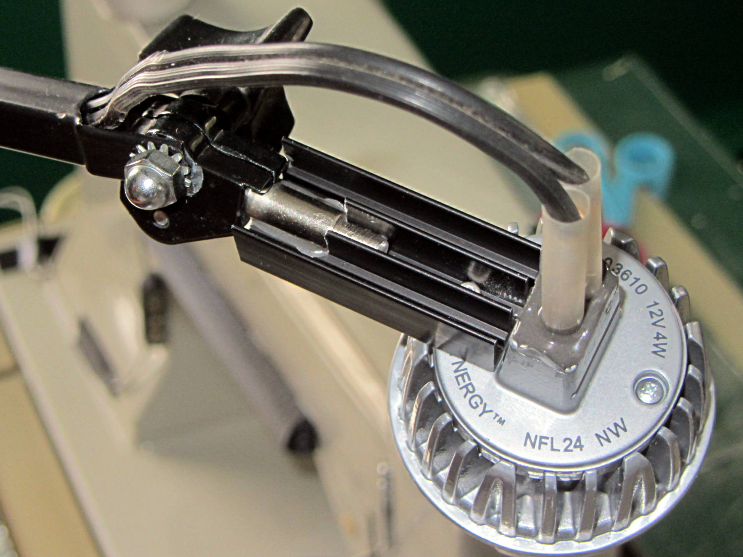
Shortly thereafter, I milled off the central fins to fit the shaft of the pivot screw, introduced the heatsink to Mr. Disk Sander to bevel the bottom, sawed the threads off the pivot, press-fit the two together, drilled a 2 mm cross-hole into the pivot, buttered it all up with epoxy, jammed a short M2 screw into the cross hole, and let the whole mess cure:
Desk Lamp LED Adapter – top view
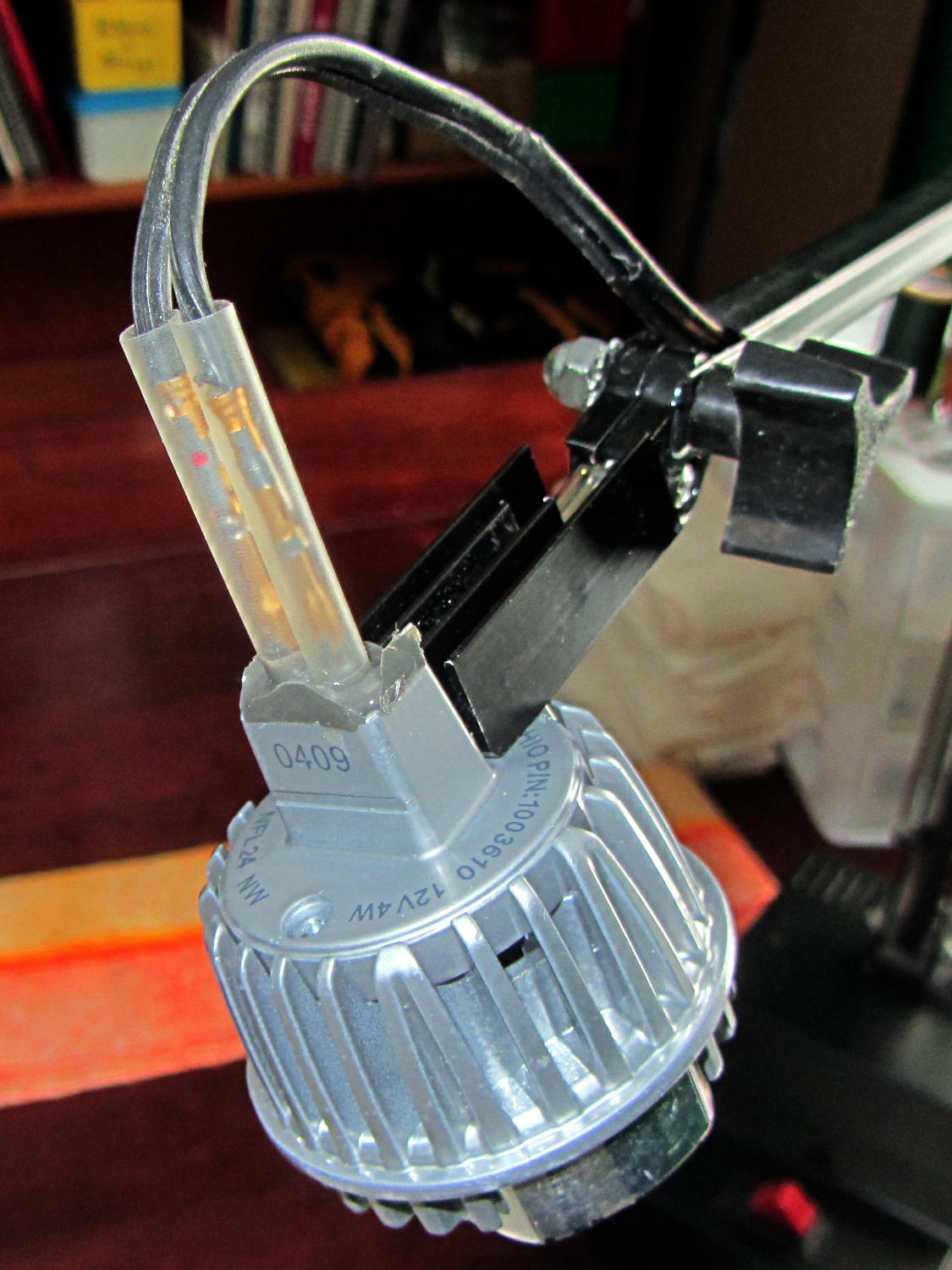
The lamp modules were a surplus find, with one pin clipped nearly flush to the insulator. I soldered a pair of the same male pins as in the battery holders, with the matching female pins as a crude connector. The unshrunk heatstink tubing isn’t lovely, but got us to First Light:
Desk Lamp LED Adapter – front view
The original counterweight is, of course, much too heavy for the dinky LED module, so I’ll drill the mounting hole for the vertical arm further back on the beam to get another foot of reach. That will require more wire between the transformer to the lamp, soooo the connectors might just become soldered joints.
As you can tell from the background, Mary snatched the lamp from my hands and put it to immediate use in The Quilting Room.
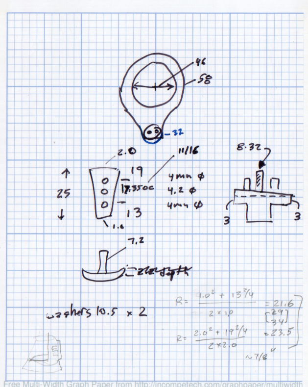
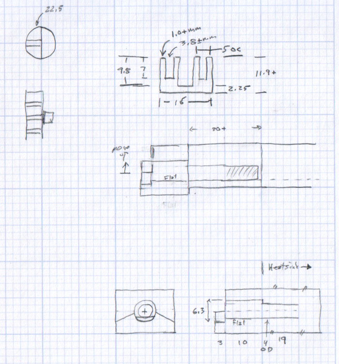
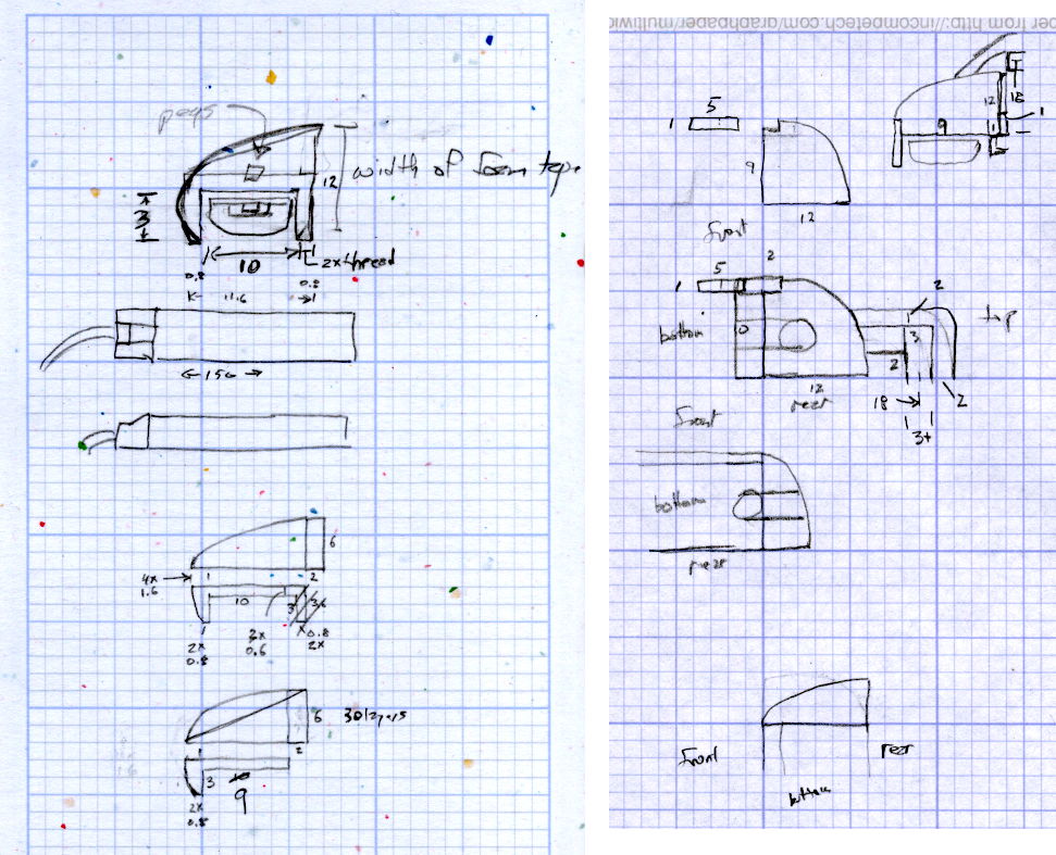
The original doodles bear no resemblance to the final product, but do have some key dimensions that (having discarded the unused hardware) I’ll likely never need again.
The pivot between the arm and the lamp housing, with an idea for the LED holder:
Desk Lamp Bracket Dimensions – doodle
Details of the repurposed heatsink and the pivot bolt, with a block that never got built:
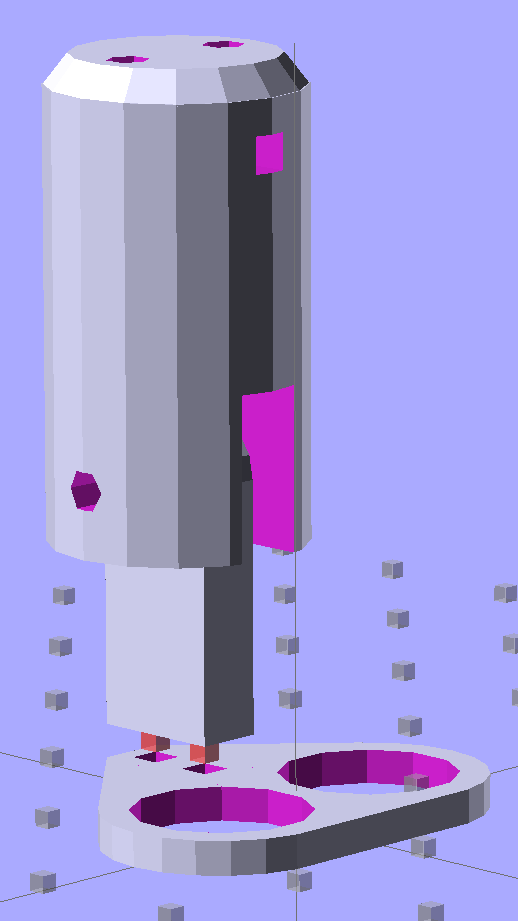
Some trial fitting with the prototype showed that there’s no possible way to route the connections through the socket, no matter how much I wanted that to happen, so I rotated the body to align the LEDs with the socket pin slots:
Sears Lamp LED Adapter – Show view
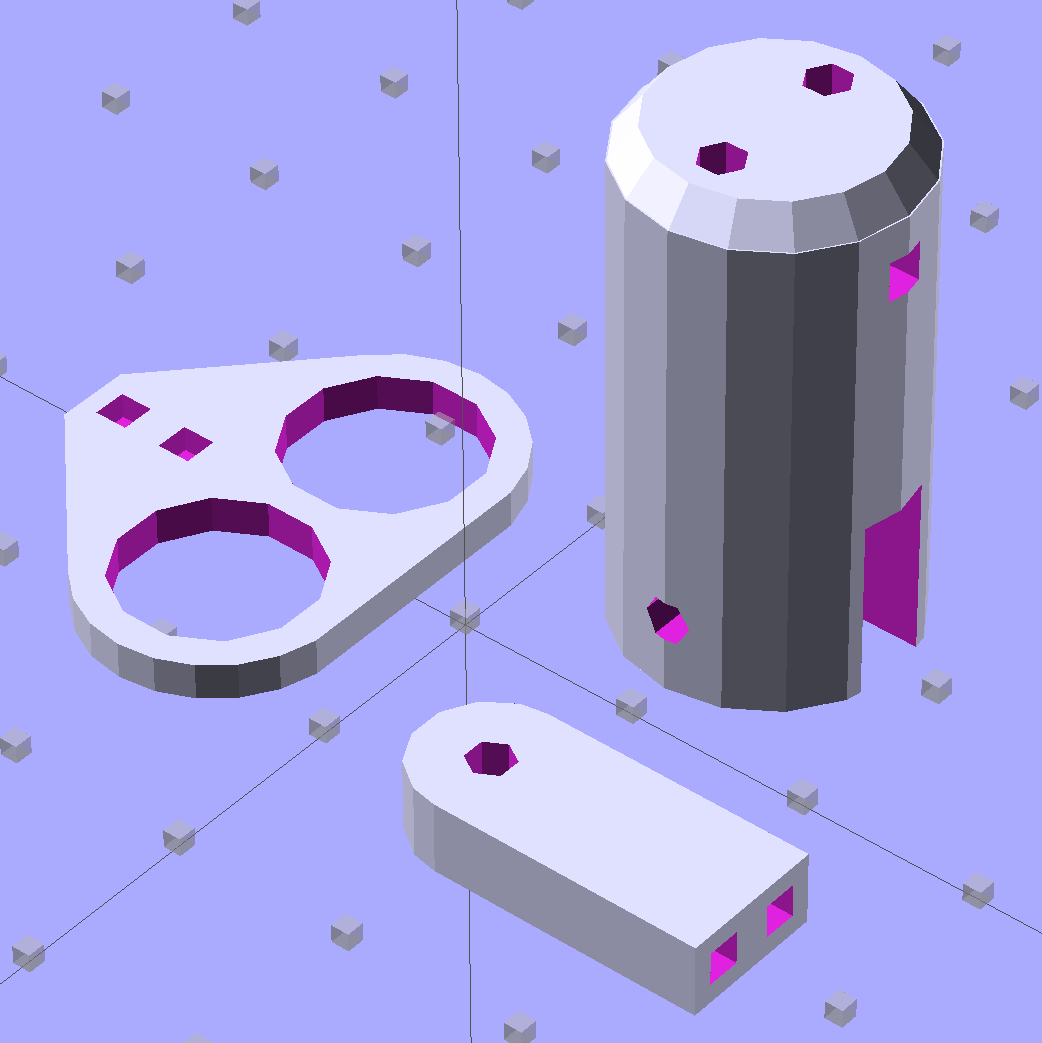
The body now builds with the flat end down, so the overall finish should be better:
Sears Lamp LED Adapter – Build view
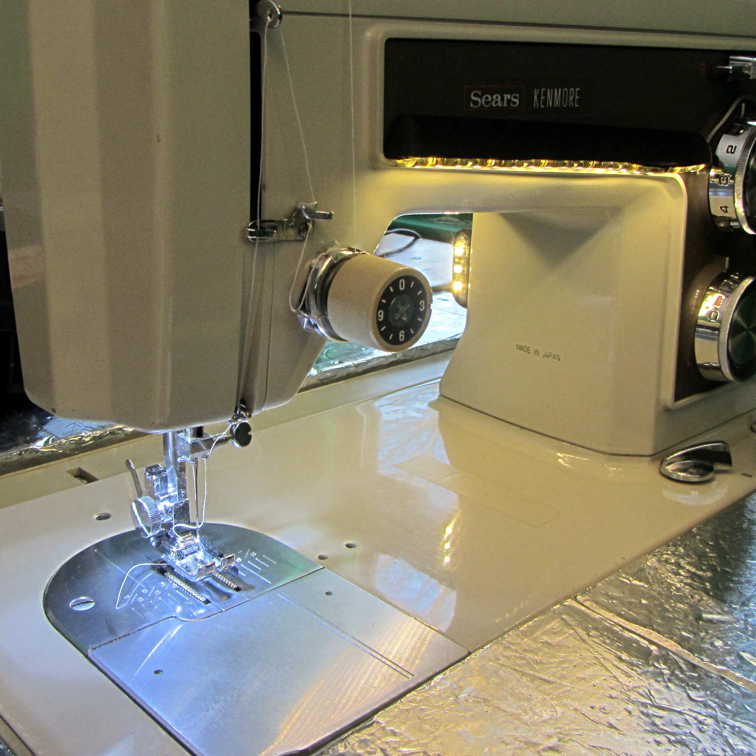
A test run shows why I really, really wanted cool white LEDs in the strips over the arm:
Kenmore 158 Sewing Machine – mixed LED lighting
The LED mount doesn’t have quite enough room inside the end cap for the holder to tilt as I wanted; the two 10 mm LEDs can be about 10 mm lower and slightly closer to the shaft driving the needle, which is what this rapid prototyping stuff is all about. Scrapping the existing lamp socket and (120 VAC!) wiring seems the best way to make this more useful.
Early reports on the arm LEDs indicate a requirement for more light, so the next iteration of those mounts will put two strips side-by-side…
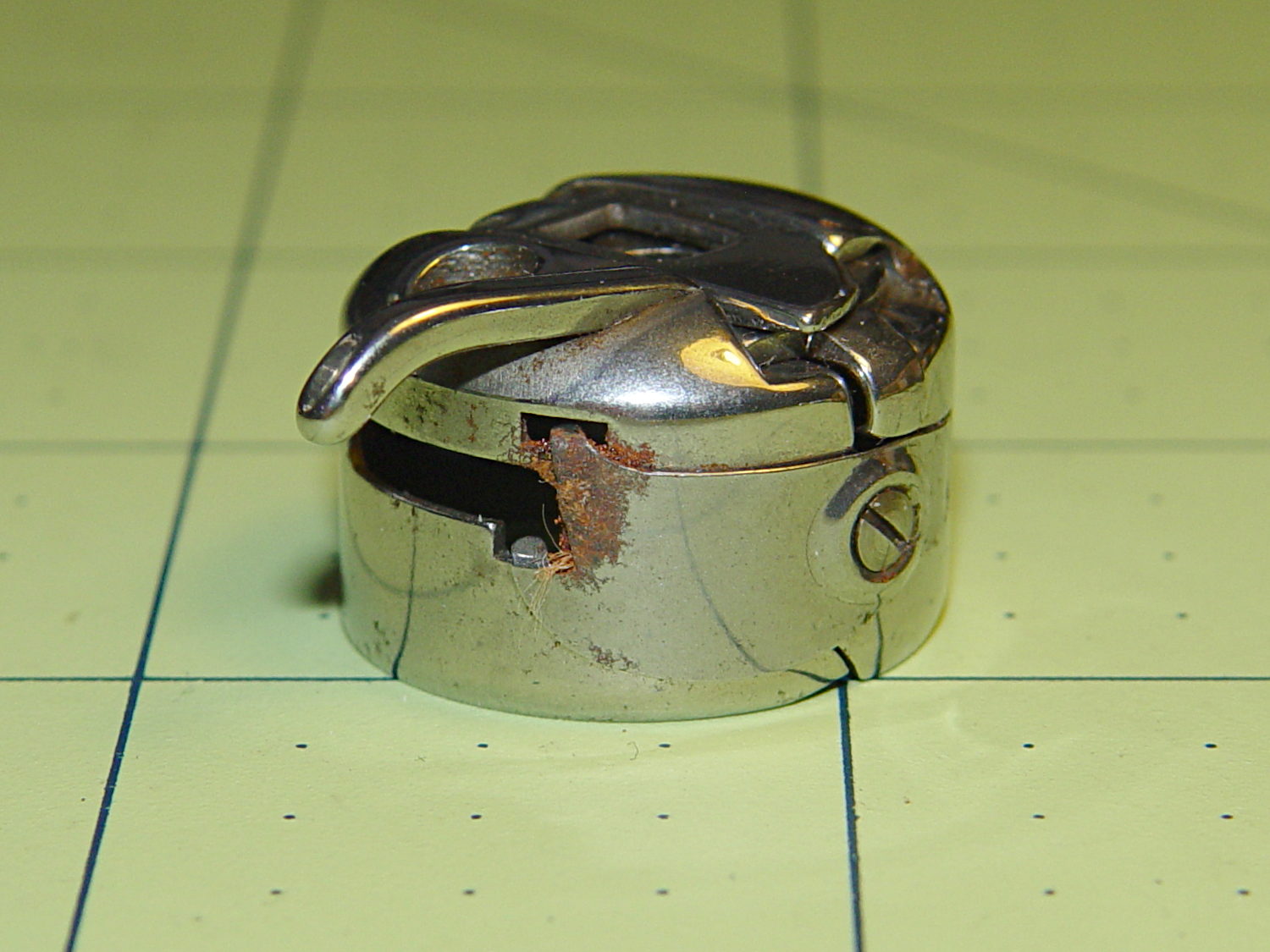
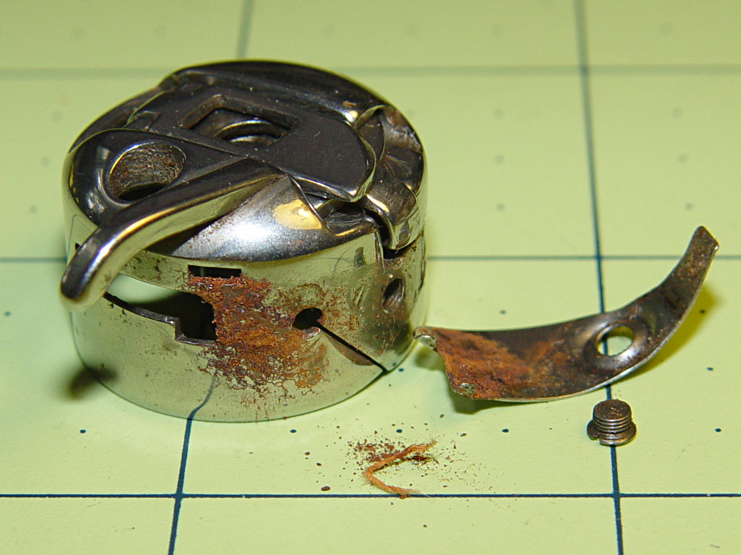
I picked up a spare sewing machine as a crash test dummy for modifications to Mary’s Kenmore Model 158. It’s in reasonably good condition, although the bobbin case showed a bit of rust:
Kenmore bobbin case – rusted overview
Taking the tension spring off revealed more rust:
Kenmore bobbin case – rusted parts
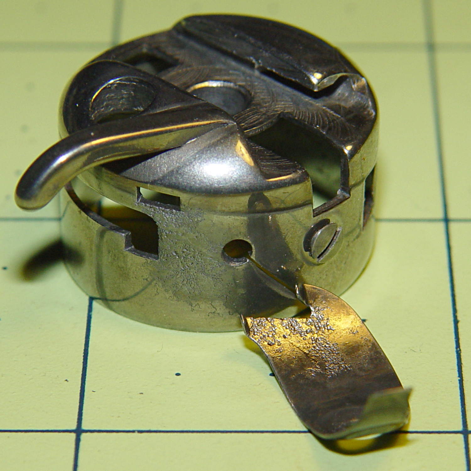
An overnight soak in Evapo-Rust got rid of the corrosion and left the pits behind:
Kenmore bobbin case – restored parts
Those imperfections on the tension spring are pits, not bumps, despite their appearance.
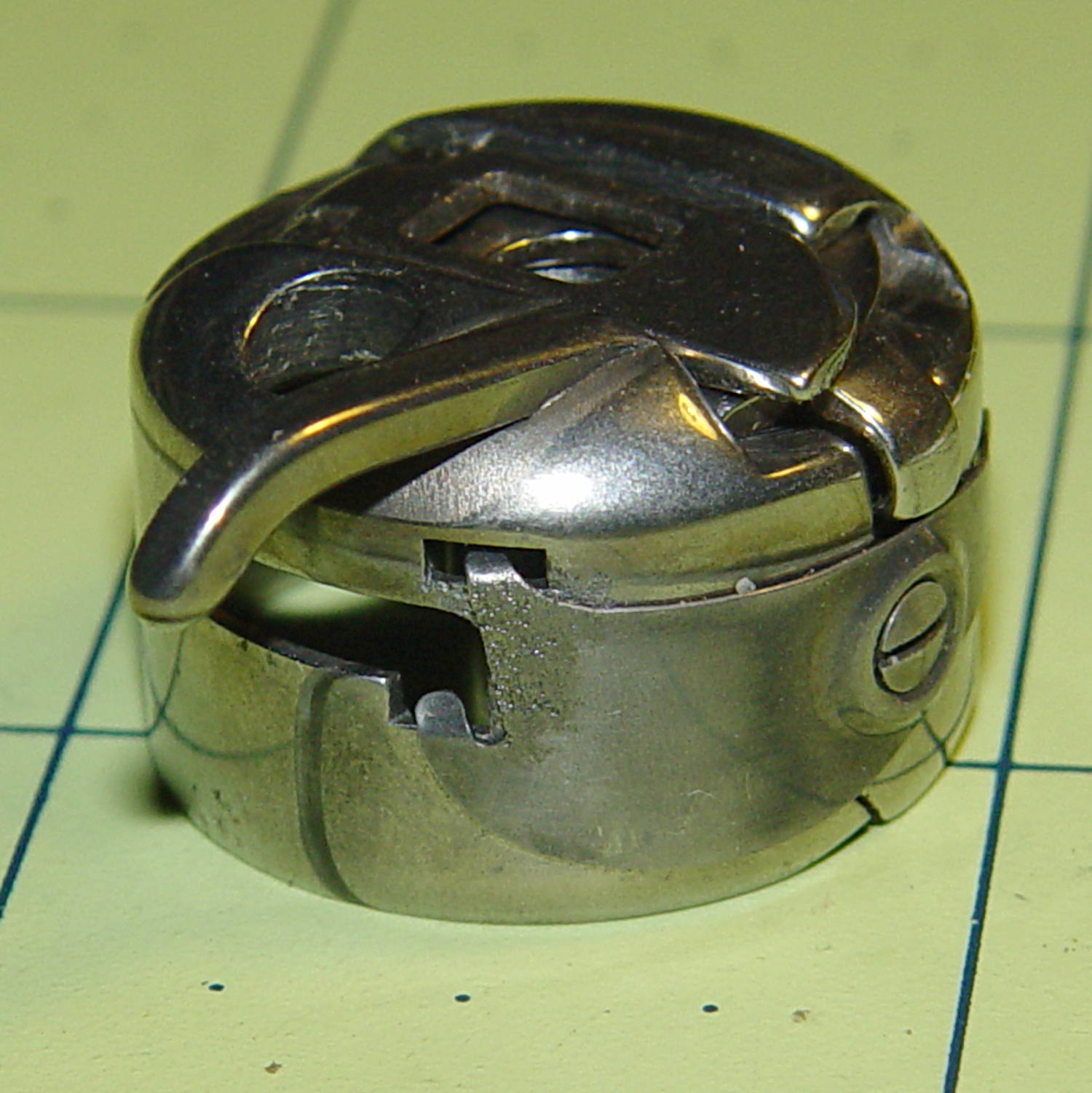
It doesn’t seem so bad from the outside:
Kenmore bobbin case – restored
It probably won’t work nearly as well as it should, this being one place where a smooth surface counts for a lot. Fortunately, it’s just a crash test dummy machine and good results aren’t critical.
Solder pretty cable with silver plating on the braid (it’s probably mil-spec Teflon dielectric RG-174 coaxial cable) to the LEDs
Conjure a coax power connector and wall wart
Apply foam squares to mounts
Affix to sewing machine
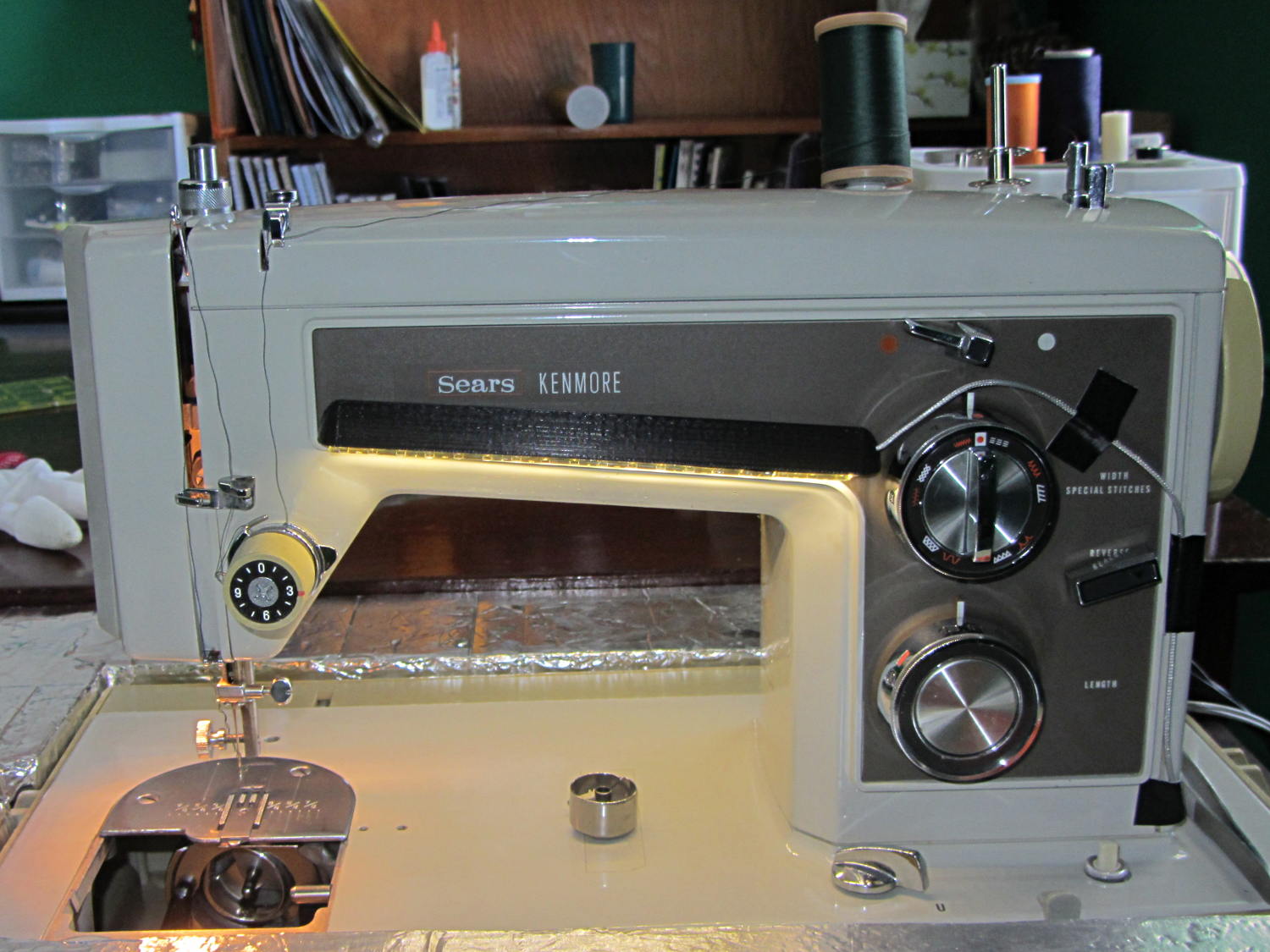
The front LEDs have a jaunty angle along the bottom of the plastic panel:
Kenmore Model 158 Sewing Machine – LED Lights – front
You can see why I want cool-white LEDs, rather than these warm-white ones, to match the daylight from the window to the right. The wash of orange light from the incandescent bulb inside the end bell has got to go, too.
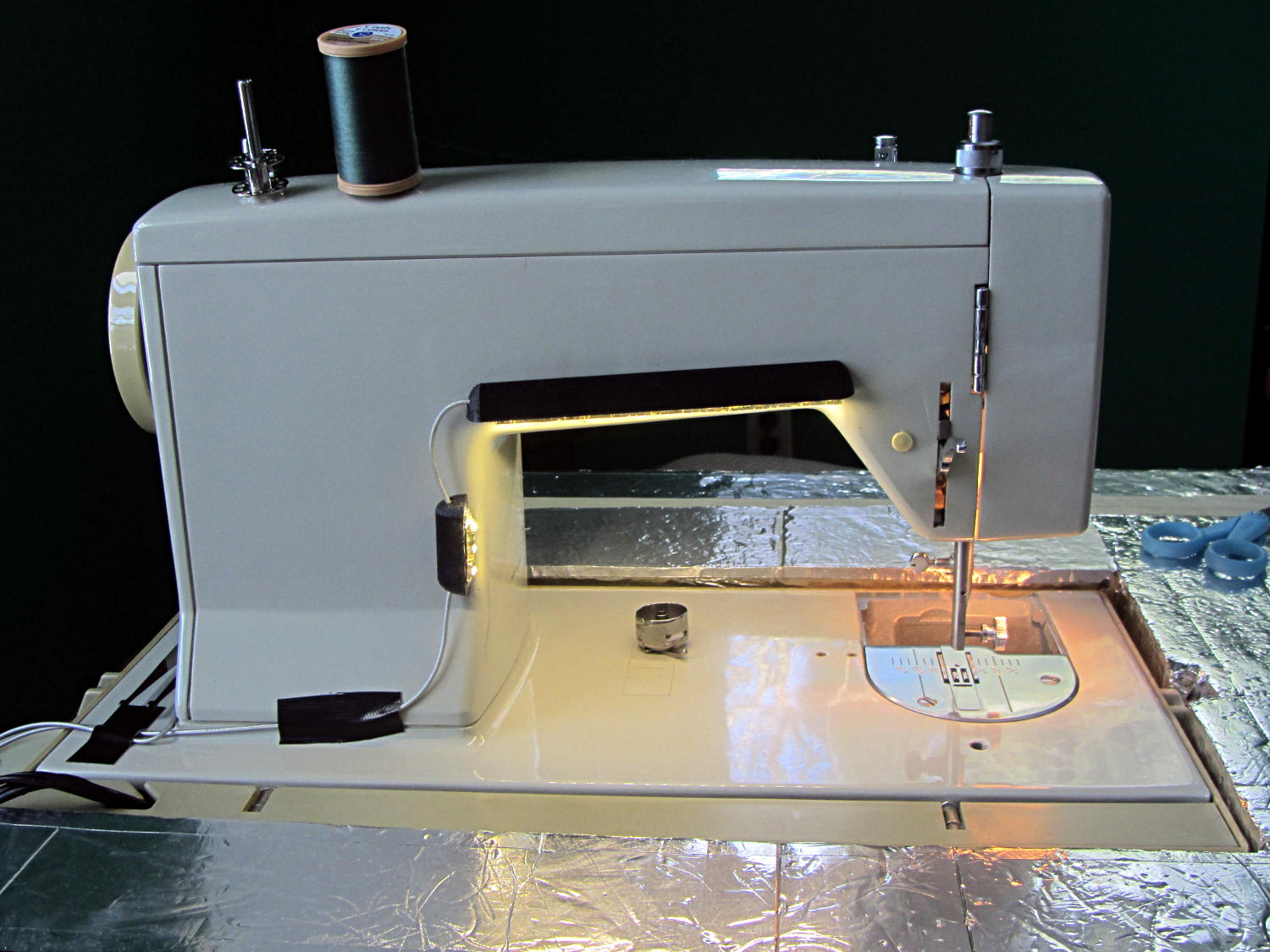
The rear LEDs over the arm may be slightly too close to the opening:
Kenmore Model 158 Sewing Machine – LED Lights – rear
The single-segment strip on the side provides a bit more light for the needle across the opening:
Kenmore Model 158 Sewing Machine – LED Lights – rear detail
Now, I’ll grant you that the strips of of black Gorilla Tape aren’t particularly attractive, but the intent here is to find out whether the LEDs produce enough light, don’t snag the quilt, and generally meet requirements.
Mary’s Sears Kenmore Model 158 sewing machine arm has a flat rear surface and a plastic plate on the front, so double-sided adhesive foam tape can hold a straight mount in place; we rejected putting strips under the arm to avoid snagging on the quilts as they pass by. So, with LEDs in hand, these are the mounts…
LED strip lights must have strain relief for their wires, as our Larval Engineer discovered the hard way on her longboard ground lighting project, and I wanted nice endcaps to avoid snagging on the fabric, so the general idea was a quarter-round rod with smooth endcaps and a hole to secure the wire. Some experiments showed that the acrylic (?) LED encapsulation directed the light downward, thus eliminating the need for a shade.
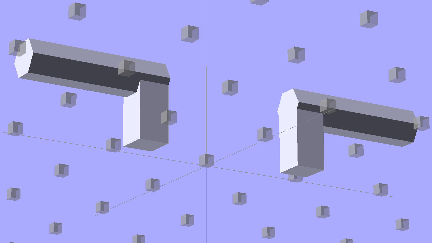
So, something like this will do for a first pass:
LED Strip Light Mount – bottom view
The overall dimensions for the LED mounts:
Length: N x 25 mm, plus endcap radii
Front-to-back width: 10 mm to allow for strip variation and 1 mm protection
Top-to-bottom height: 12 mm to fit double-sided foam sticky squares
Wire channels: 3 mm diameter or square cross-section
If there’s not enough light, I think a double-wide mount with two parallel LED strips would work.
After a bit of screwing around with additive endcaps that produced catastrophically non-manifold solid models, I figured out the proper subtractive way to build the mounts: the endcaps actually define the overall shape of the mount.
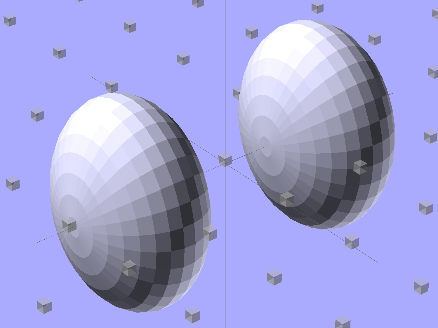
Start by placing a pair of spheroids, with radii matching the strip dimensions, so that their outer poles match the desired overall length:
Strip Light Mount – end cap spheroids – whole
The north/south poles must face outward, so that the equal-angle facets along the equators match up with what will become the mount body: rotate the spheroids 90° around the Y axis. The centers lie at the ends of the LED segments; the model shown here has a single 25 mm segment.
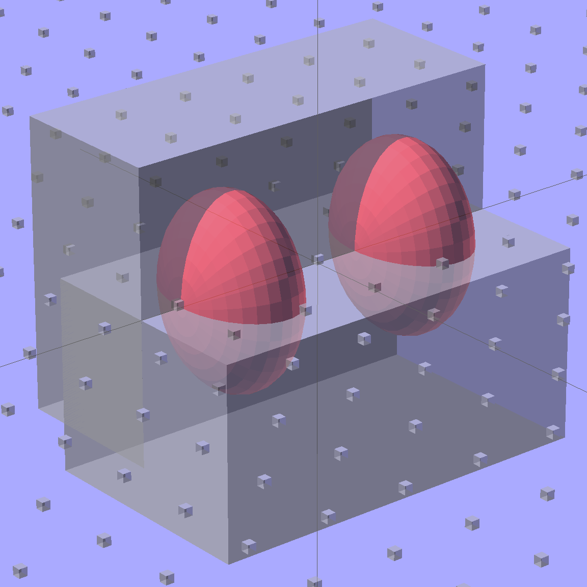
Then hack off three quadrants:
Strip Light Mount – end cap spheroids
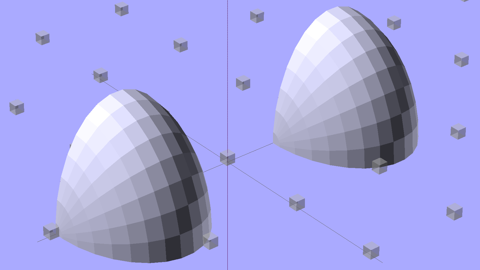
That leaves two orange-segment shapes that define the endcaps:
Strip Light Mount – end caps – shaped
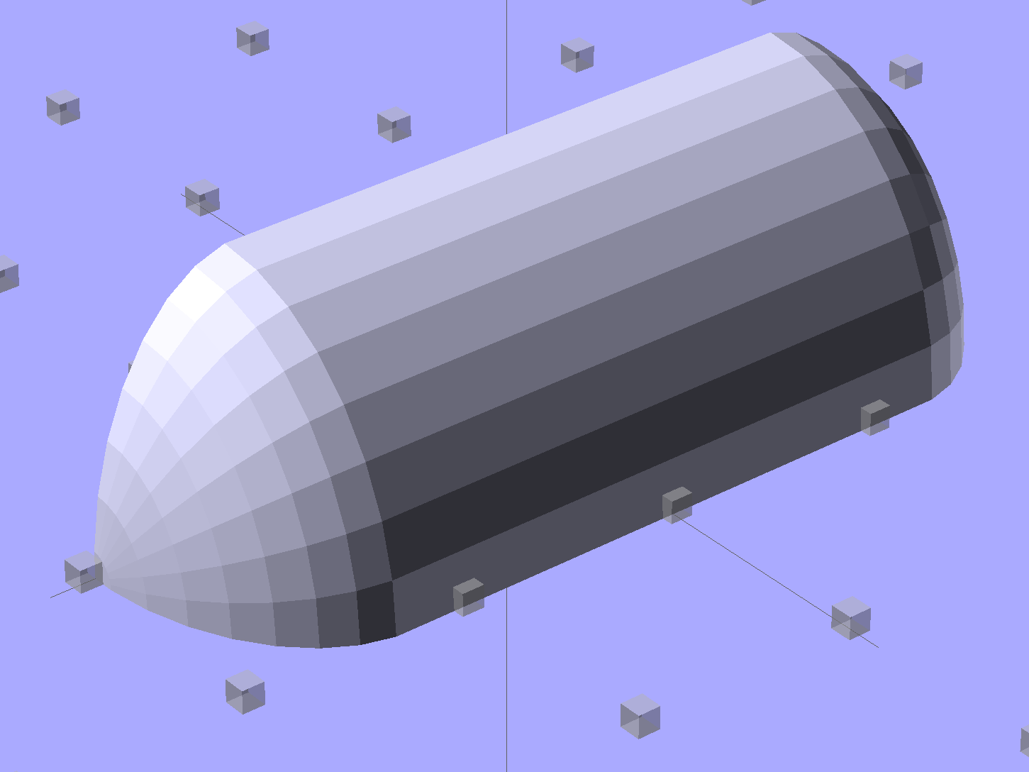
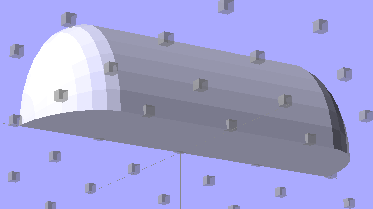
Here’s the key step that took me far too long to figure out. Shrinkwrapping the endcaps with the hull() function finesses the problem of matching the body facets to the endcap facets:
Strip Light Mount – end caps – hull
Model the wire channels as positive volumes that will be subtracted from the mount. The Channels layout shows both channels separated by a short distance:
Strip Light Mount – positive wire channels
The horizontal hexagons started as squares, but that looked hideous on the rounded endcaps.
Seen from the bottom, the mount starts like this:
Strip Light Mount – no wiring channels
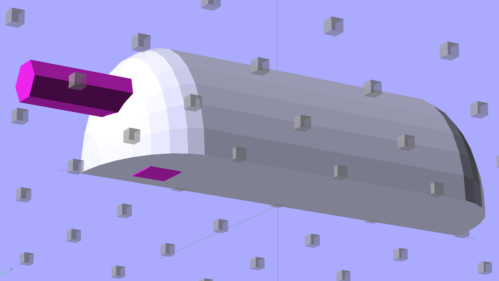
Position and subtract a wire channel:
Strip Light Mount – visible wire channel
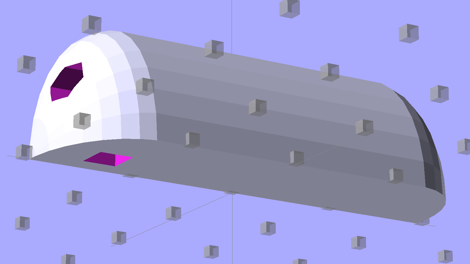
Which leaves the final solid model as a single, manifold object:
Strip Light Mount – complete
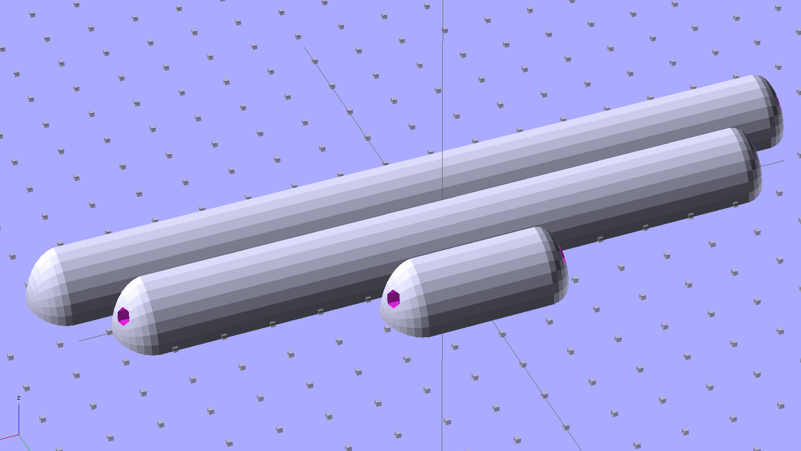
The module generating the mount takes three parameters: the number of LED segments and two string variables that determine whether to punch a channel in each endcap. Instantiate the module three times with suitable parameters to get a trio of LED mounts, all laid out for 3D printing:
Strip Light Mount – build layout
They built just exactly like those models would suggest; the M2 produces dependable results.
The OpenSCAD source code:
// LED Strip Lighting Brackets for Kenmore Model 158 Sewing Machine
// Ed Nisley - KE4ZNU - February 2014

Layout = "Strip";			// Build Show Channels Strip

//- Extrusion parameters must match reality!
//  Print with 2 shells and 3 solid layers

ThreadThick = 0.20;
ThreadWidth = 0.40;

HoleWindage = 0.2;			// extra clearance

Protrusion = 0.1;			// make holes end cleanly

AlignPinOD = 1.70;			// assembly alignment pins: filament dia

inch = 25.4;

function IntegerMultiple(Size,Unit) = Unit * ceil(Size / Unit);

//----------------------
// Dimensions

Segment = [25.0,10.0,3.0];		//  size of each LED segment

WireChannel = 3.0;				// wire routing channel

StripHeight = 12.0;				// sticky tape width
StripSides = 8*4;

DefaultLayout = [1,"Wire","NoWire"];

EndCap = [(2*WireChannel + 1.0),Segment[1],StripHeight];	// radii of end cap spheroid
EndCapSides = StripSides;

CapSpace = 2.0;						// build spacing for endcaps
BuildSpace = 1.5*Segment[1];		// spacing between objects on platform

//----------------------
// Useful routines

module PolyCyl(Dia,Height,ForceSides=0) {			// based on nophead's polyholes

  Sides = (ForceSides != 0) ? ForceSides : (ceil(Dia) + 2);

  FixDia = Dia / cos(180/Sides);

  cylinder(r=(FixDia + HoleWindage)/2,
           h=Height,
           $fn=Sides);
}

module ShowPegGrid(Space = 10.0,Size = 1.0) {

  RangeX = floor(100 / Space);
  RangeY = floor(125 / Space);

	for (x=[-RangeX:RangeX])
	  for (y=[-RangeY:RangeY])
		translate([x*Space,y*Space,Size/2])
		  %cube(Size,center=true);

}

//-- The negative space used to thread wires into the endcap

module MakeWireChannel(Which = "Left") {

	HalfSpace = EndCap[0] * ((Which == "Left") ? 1 : -1);

	render(convexity=2)
	translate([0,EndCap[1]/3,0])
		intersection() {
			union() {
				cube([2*WireChannel,WireChannel,EndCap[2]],center=true);
				translate([-2*EndCap[0],0,EndCap[2]/2])
					rotate([0,90,0]) rotate(180/6)
						PolyCyl(WireChannel,4*EndCap[0],6);
			}
			translate([HalfSpace,0,(EndCap[2] - Protrusion)]) {
				cube(2*EndCap,center=true);
			}
		}
}

//-- The whole strip, minus wiring channels

module MakeStrip(Layout = DefaultLayout) {

	BarLength = Layout[0] * Segment[0];				// central bar length

	hull()
		difference() {
			for (x = [-1,1])						// endcaps as spheroids
				translate([x*BarLength/2,0,0])
					resize(2*EndCap) rotate([0,90,0]) sphere(1.0,$fn=EndCapSides);
			translate([0,0,-EndCap[2]])
				cube([2*BarLength,3*EndCap[1],2*EndCap[2]],center=true);
			translate([0,-EndCap[1],0])
				cube([2*BarLength,2*EndCap[1],3*EndCap[2]],center=true);
		}

}

//-- Cut wiring channels out of strip

module MakeMount(Layout = DefaultLayout) {

	BarLength = Layout[0] * Segment[0];

	difference() {
		MakeStrip(Layout);
		if (Layout[1] == "Wire")
			translate([BarLength/2,0,0])
				MakeWireChannel("Left");
		if (Layout[2] == "Wire")
			translate([-BarLength/2,0,0])
				MakeWireChannel("Right");
	}
}

//- Build it

ShowPegGrid();

if (Layout == "Channels") {
	translate([ EndCap[0],0,0]) MakeWireChannel("Left");
	translate([-EndCap[0],0,0]) MakeWireChannel("Right");
}

if (Layout == "Strip") {
	MakeStrip(DefaultLayout);
}

if (Layout == "Show") {
	MakeMount(DefaultLayout);
}

if (Layout == "Build") {

	translate([0,BuildSpace,0]) MakeMount([1,"Wire","Wire"]);		// rear left side, vertical
	translate([0,0,0]) MakeMount([5,"Wire","NoWire"]);				// rear top, across arm
	translate([0,-BuildSpace,0]) MakeMount([6,"NoWire","Wire"]);	// front top, across arm
}
The original design doodles, which bear a vague resemblance to the final mounts:
LED Strip Light Mounts – Original Design Sketches
The little snood coming out of the top would hide a wire going through a hole drilled in the capital-S of “Sears” on the front panel, but I came to my senses long before implementing that idea…
No snagging on a bulky quilt shoved through the machine
Not completely butt-ugly
Reasonably durable
I picked up reels of cool-white and warm-white waterproof LED strips (12 V, 3528-size chips, 5 m, 600 LED, 25 mm segments) from the usual eBay supplier, who promptly charged for both and shipped only the warm-white reel. Cool-white LEDs will be a better color match to daylight from the window and the little Ottlite she uses for detail work, but I ran some prototypes while we wait for the replacement.
The Chinese New Year really comes in handy as an excuse for screwing things up and not responding for a week or two. ‘Nuff said.
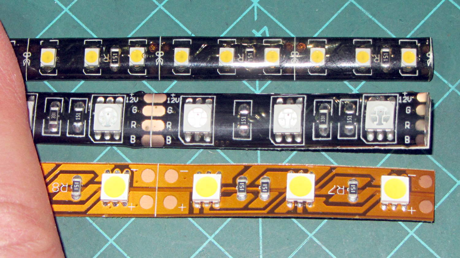
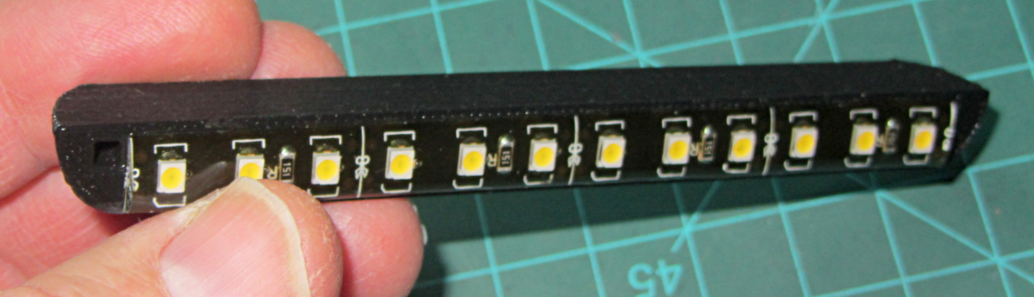
They’re similar to the RGB LEDs from a while ago, with even gummier “waterproof” encapsulation. I got double-density 600 LED strips to put more light emitters across the arm:
Various LED strip lights
The smaller 3528 SMD LEDs (vs. 5050 chips in the others) allow a narrower strip and the double-density layout means each three-LED segment is half as long long. The as-measured dimensions work out to:
25.0 mm segment length
8.2 mm strip width
2.5 mm thickness
The sealant thickness varies considerably, so I’d allow 3.0 mm for that in case it mattered. It slobbers over the edge of the strip here and there; allowing at least 9.0 mm would be wise.
The SMD resistor in each segment is 150 Ω. A 5 segment length drew 85 mA @ 12 V = 17 mA/segment. Boosting the voltage to 12.8 V got the current to the expected 100 mA = 20 mA/segment.
The LEDs are noticeably less bright than the 5050 LEDs, even at 20 mA/segment, but I think they’ll suffice for the task.
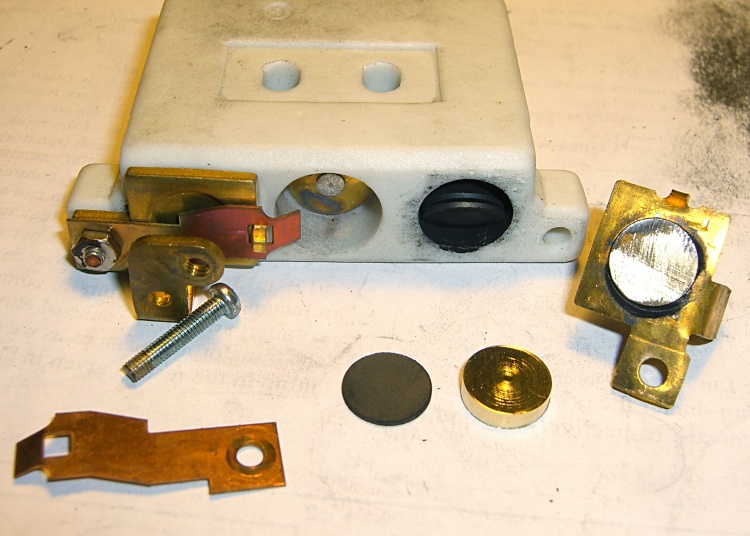
The speed control pedal on Mary’s sewing machine once again started racing away from a dead stop, which we now know means more disks inside the carbon pile rheostat have disintegrated. It looked pretty much the same as when I took it apart in 2009:
Rheostat graphite wafers and contacts
This time, it had one cracked wafer and several thin ones, reducing the length of the stacks so much that the pedal exerted very little force (thus, not starting the motor) before the shorting contacts caused a runaway.
Back then, I’d machined two brass disks to fill the empty space:
Rheostat with brass spacer button
A rough measurement showed I’d have to double their thickness to about 7 mm each, but it seemed like replacing high-resistance carbon with low-resistance brass wasn’t a Good Idea, at least when taken to an extreme. Not knowing what would count as an extreme in this situation, I decided to replace the brass disks with graphite cylinders sized to fill up the empty space.
The Little Box o’ Machinable Graphite produced a small bar, from which I sliced a square with jeweler’s pull saw:
Machineable Graphic – rough-sawn slab
Cutting that in half, then one of the bars in half, produced a pair of cubes:
Machineable Graphic – cubes
I tried sanding off the corners:
Machineable Graphic – sanded cube
After it became painfully obvious that process would take just slightly less than forever, I deployed the Dremel sanding drum:
Machineable Graphic – cylinders
Much to my surprise, the shop vacuum didn’t quite inhale the cloth, I didn’t drop either of the cylinders into its gaping maw or sand away my fingertips, and the cylinders emerged more-or-less good looking. I sanded the faces reasonably smooth and parallel, removed a few high spots left by the Dremel, and the cylinders slid neatly into the holes in the ceramic rheostat.
I felt a definite kinship with those guys in the rackets (not squash, as I once knew) court under the stadium seats…
I put the cylinders at the end of the stacks, against the graphite buttons (shown in the top picture), and left the disks to settle themselves against the brass contacts. In retrospect, I should have put the cylinders against the brass, so that the inevitable erosion will chew on the (relatively) easily replaced bulk cylinders.
Each graphite cylinder displaced six disks, so now I have some spares for next time. I’m certain that the graphite has lower resistance than the equivalent length of disks, but it’s probably higher than the same length of brass. I was not going to slice those cylinders into disks.
After vigorous and repeated handwashing with gritty cleaner after leaving the Basement Laboratory Workshop, the pedal assembly went back together smoothly and, once again, operates the way it should: controllable smooth low speeds, crazy-fast high speeds, and a steady transition between the two. Mary has resumed quilting up a storm.
That shop vacuum may never forgive me, but it totally eliminated all the carbon dust from the work area. The filter started out coated with a generous layer of dust and crud, so I’m pretty sure it collected most of the very fine dust, too.
I briefly considered using the lathe, but came to my senses.
The cheap way to do AC motor speed control involves a triac chopping the sine wave, so as to produce all manner of hash above and beyond the usual motor commutation noise. It occurs to me that the sewing machine has a universal motor that would run just as happily on 120 V DC as it does on AC, so a cheap 120 V DC supply (around 2 A should suffice) from the usual eBay supplier and a high voltage MOSFET on a generous heatsink would work even better. One might even get by with just a full-wave rectifier bridge and pulsating DC.
The rheostat doesn’t dissipate more than a few watts, I think, so thermal management should not pose a serious problem.
The motor rating says it’s good for 1 A, which means the power should be less than a few tens of watts. Some resistance and current measurements are in order.
You can actually buy replacement pedals, but what’s the fun in that?