Ed Nisley's Blog: Shop notes, electronics, firmware, machinery, 3D printing, laser cuttery, and curiosities. Contents: 100% human thinking, 0% AI slop.
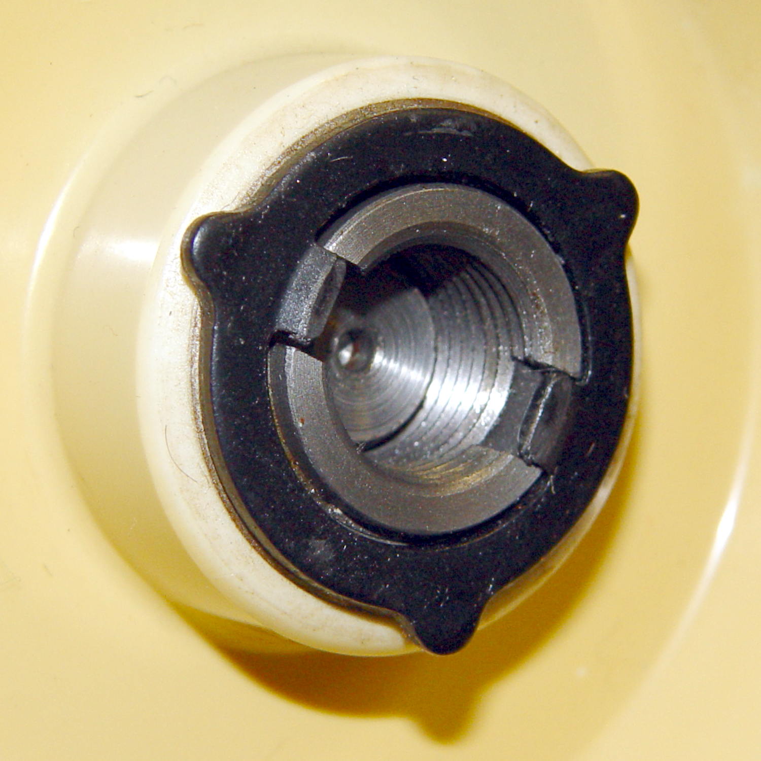
The handwheel on the Kenmore Model 158 sewing machine has a shiny knurled knob in the middle:
Kenmore 158 handwheel – knob
Turning the knob clockwise screws the knob inward and clamps a friction clutch that locks the handwheel to the main shaft; the motor belt drives the handwheel, the handwheel drives the shaft, and the shaft drives everything inside the sewing machine.
Remove the small screw, turn the knob counterclockwise to remove it, and you see the clutch:
Kenmore 158 – handwheel clutch – detail
Yes, the black stamped metal part is the clutch.
Those three projections around the exterior limit the knob’s travel to a bit under 1/3 turn, with the little screw you just removed traveling between two of the projections. When you reinstall the knob:
Turn it until it’s snug
Insert and tighten the screw
Done!
The two dogs in the middle project outward from the shaft notches: the bases engage the notches, the tips bears on the knob’s inner surface. Tightening the knob compresses the dogs, presses the clutch against the handwheel, and locks everything together.
It’s entirely possible to install the clutch backwards and, while it’ll come pretty close to working, it’s not quite right.
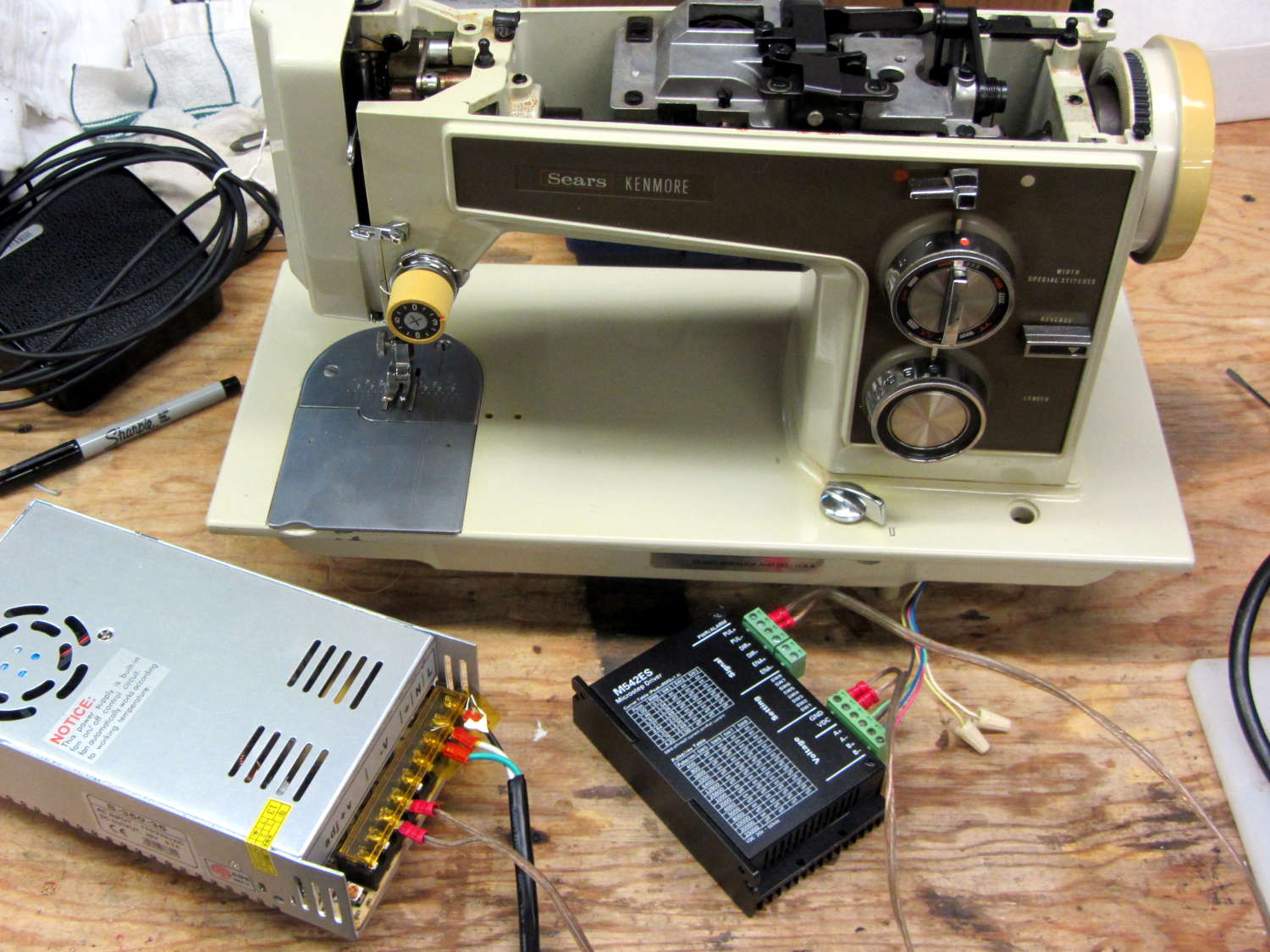
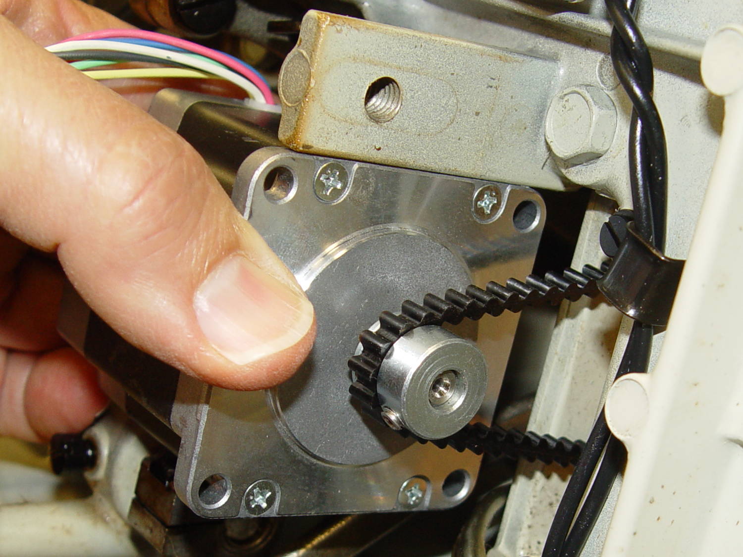
Having a NEMA 23 stepper fit almost exactly into the spot vacated by the sewing machine’s AC motor was too good to pass up:
Kenmore 158 – NEMA 23 stepper – on adapter
So I wired a power supply to an M542 stepper driver brick, connected the pulse output of a function generator to the brick’s STEP inputs, swapped motor leads until it turned the proper direction (CCW as seen from the shaft end), and turned the function generator knob:
Kenmore 158 – NEMA 23 stepper test
The object was to find the step frequency where the motor stalls, for various winding currents and supply voltages. The motor won’t have enough torque to actually stitch anything near the dropout speed, but this will give an indication of what’s possible.
With a 24 V DC supply and 1/8 microstepping (40 k step/s = 1470 RPM):
1.00 A = 11 k step/s
1.91 A = 44 k/s
2.37 A = 66 k/s
3.31 A = 15 k/s
With a 36 V DC supply and 1/8 microstepping:
1.91 A = 70 k/s
3.31 A = 90 k/s
With a 36 V DC supply and 1/4 microstepping (40 k step/s = 2900 RPM):
1.91 A = 34 k/s
2.37 A = 47 k/s
2.84 A = 47 k/s
3.31 A = 48 k/s
The motor runs faster with a higher voltage supply, which is no surprise: V = L di/dt. A higher voltage across the winding drives a faster current change, so each step can be faster.
The top speed is about 3500 RPM; just under that speed, the motor stalls at the slightest touch. That’s less than half the AC motor’s top speed under a similarly light load and the AC motor still has plenty of torque to spare.
90 k step/s at 1/8 microstepping = 11 k full step/s = crazy fast. Crosscheck: 48 k step/s at 1/4 microstepping = 12 k full step/s. The usual dropout speed for NEMA 23 steppers seems to be well under 10 k full step/s, but I don’t have a datasheet for these motors and, in any event, the sewing machine shaft provides enough momentum to keep the motor cruising along.
One thing I didn’t expect: the stepper excites howling mechanical resonances throughout its entire speed range, because the adapter plate mounts firmly to the cast aluminum frame with absolutely no damping anywhere. Mary ventured into the Basement Laboratory to find out what I was doing, having heard the howls upstairs across the house.
She can also hear near-ultrasonic stepper current chopper subharmonics that lie far above my audible range, so even if the stepper could handle the speed and I could damp the mechanics, it’s a non-starter for this task.
Given that the AC motor runs on DC, perhaps a brute-force MOSFET “resistive” control would suffice as a replacement for the carbon disk rheostat in the foot pedal. It’d take some serious heatsinking, but 100 V (or less?) at something under 1 A and intermittent duty doesn’t pose much of a problem for even cheap surplus MOSFETs these days.
That would avoid all the electrical and acoustic noise associated with PWM speed control, which counts as a major win in this situation. Wrapping a speed control feedback loop around the motor should stiffen up its low end torque.
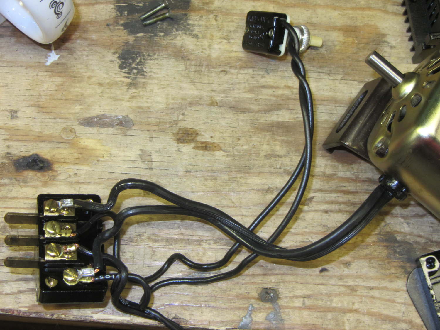
For completeness, the matching socket (not shown) joins two cords:
AC line cord (two wire, not polarized, no ground)
Foot pedal
Extract the motor wiring from that block and connect it to a 50 V / 3 A bench supply, with the positive lead to the marked wire conductor:
Kenmore 158 AC motor – DC power
Cranking the voltage upward from zero:
Kenmore Model 158 AC Motor on DC – RPM vs V
So that’s about 200 RPM/V, offset by 2800 RPM. Totally unloaded, of course.
The original data:
DC V
DC A
RPM
Notes
15
0.29
690
Barely turning
20
0.28
1380
Finger-stoppable
25
0.29
2350
30
0.29
3450
35
0.30
4450
40
0.29
5740
45
0.29
6780
Still finger-holdable at start
50
0.29
8000
I can hold the shaft stopped between my fingers up through 45 V, with 0.54 A locked-rotor current at 25 V. The motor doesn’t have a lot of torque, although it’s operating at less than half the normal RMS voltage.
I should take those numbers with the motor driving the sewing machine to get an idea of the actual current under a more-or-less normal load.
Reversing the power supply leads shows that the motor rotates only counterclockwise, which is exactly what you’d expect: both polarities of the normal AC sine wave must turn the motor in the same direction.
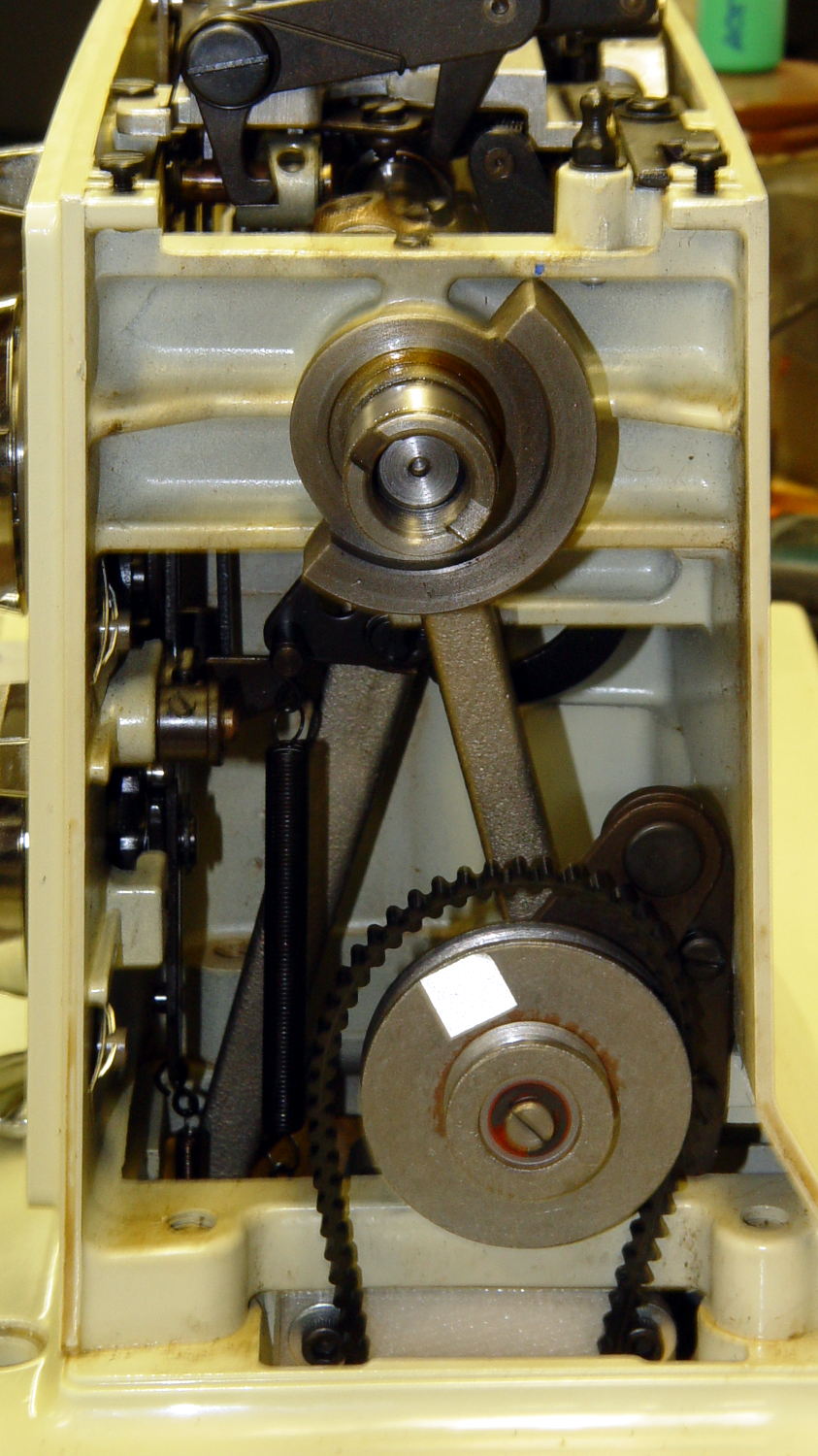
Fancy new sewing machines can stop with the needle either up (so you can remove the fabric) or down (to nail it in place while you rotate it). This requires sensing the needle position, which prompted me to spend far too long contemplating all the mechanical gadgetry driven by the motor.
As nearly as I can tell, the crank counterweight behind the handwheel produces the most unambiguous position reports. Here’s what it looks like with the needle down:
Kenmore 158 – main shaft counterweight
As you’d expect, with the shaft rotated exactly 180° from that point, the needle is up.
The inviting space just above the shaft provides room for the bobbin winder that engages a knurled ring on the back of the handwheel, but the lower space seems to be available. The counterweight sits about halfway into the back of the handwheel, so the sensors must look at the frame side of the counterweight.
Two adjacent sensors could detect the edge of the counterweight, which would be enough to uniquely identify both positions. If they were spaced across the lower-left edge in that picture:
01 = trailing edge = bottom dead center = needle down (as shown)
00 = open air = needle rising
10 = leading edge = top dead center = needle up
11 = solid steel = needle falling
Either sensor gives you one pulse per handwheel revolution and the combination gives you a quadrature output of both position and direction. The top speed of 1000 RPM produces 17 Hz square waves.
An additional pulse/rev sensor on the motor shaft would give better control over the motor speed, as the handwheel runs at 1/10 the motor speed with belt slip built right in. Figure 10 kRPM → 170 Hz pulses.
From a cold start, you know the shaft angle to within a bit under 180°. If the motor can turn in both directions (as would a stepper or DC motor), you can always move the needle upward. If it turns only forward (as does the AC motor) and the needle is falling, then you probably don’t want to move the motor until you get a button push indicating that all fingers are clear.
A pair of Hall effect sensors might suffice to detect that big hunk of steel, perhaps with a pair of teeny magnets glued to the face or a magnetic circuit closed by the counterweight.
Huh. Who’d’a thunk it? That’s just too good to pass up…
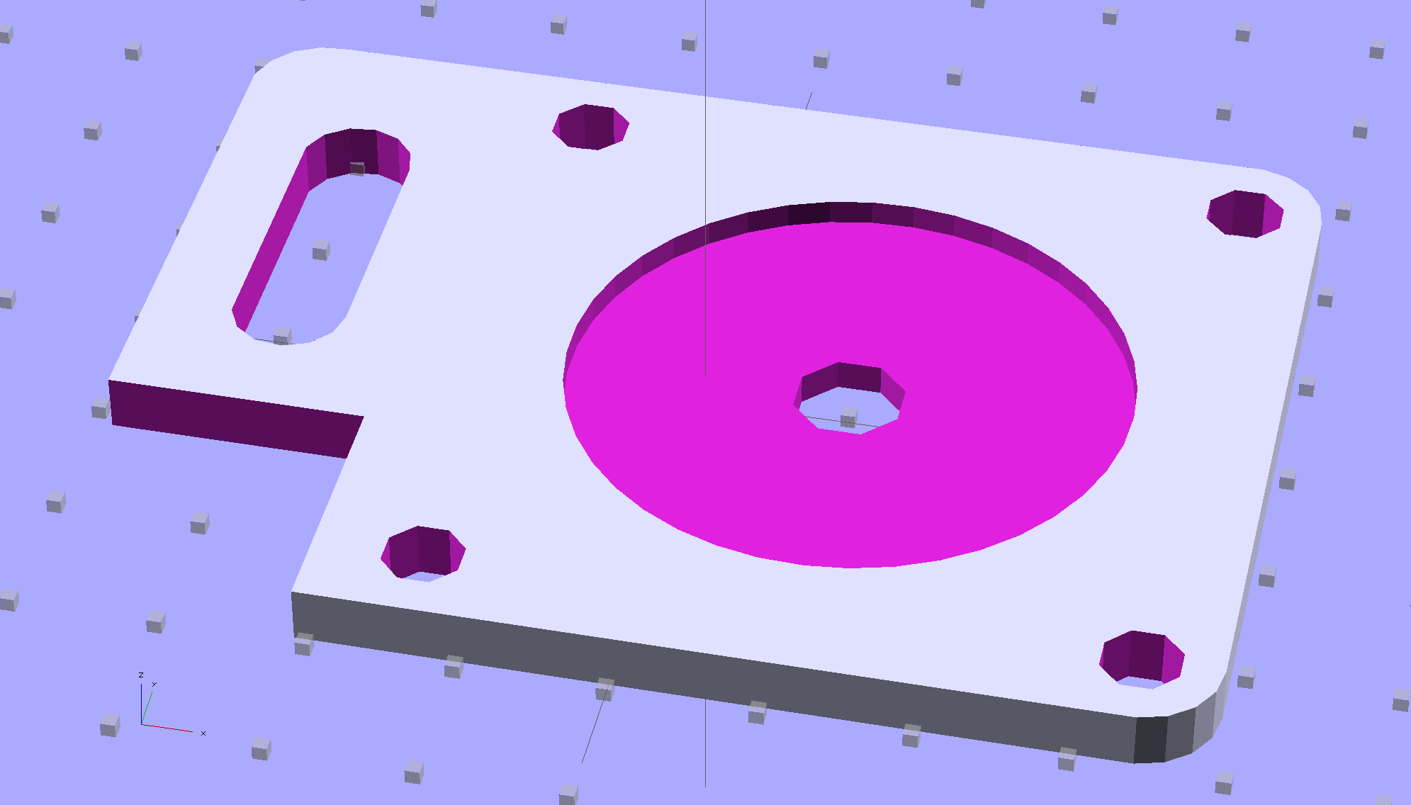
Although you wouldn’t use PLA for the real motor mount, this was easy:
Drive Motor Mount – solid model
And the whole affair fits pretty much like you’d expect:
Kenmore 158 – NEMA 23 stepper – on adapter
The NEMA 23 motor doesn’t have the same end profile as the AC motor and the adapter plate gets in the way of the pulley, but flipping the pulley end-for-end perfectly aligned the belt.
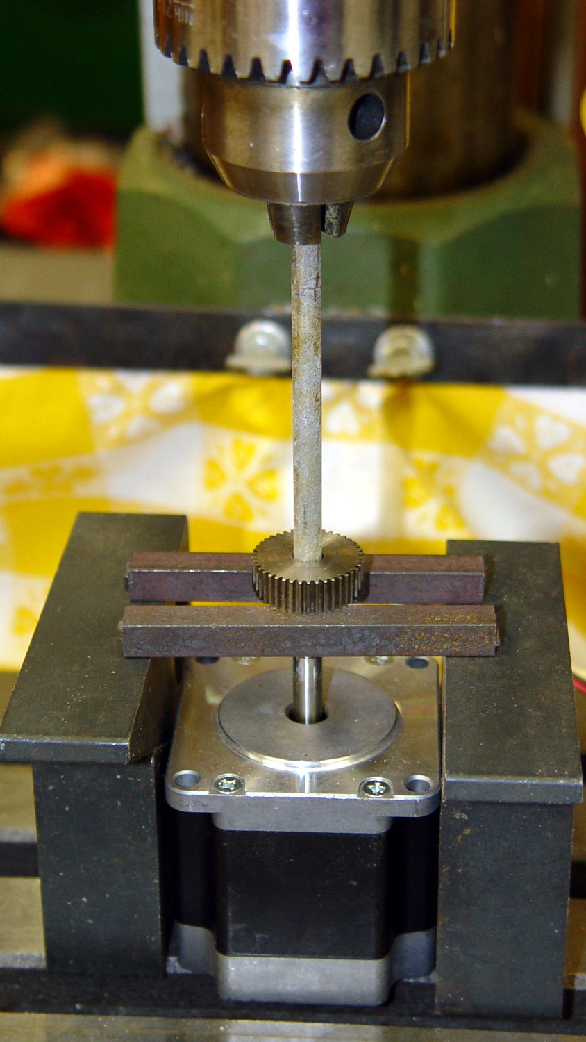
For whatever it’s worth, here’s how I removed the pressed-on gear from the shaft:
NEMA 23 Stepper – removing gear
I’m pretty sure I have a little gear puller somewhere, but it’s not where I expected to find it, which means it could be anywhere.
Much to my astonishment, the shafts on both motors are exactly 1/4″ inch. I filed a flat on the shaft to avoid having the setscrew goober the poor thing.
A stepper isn’t the right hammer for this job, because it can’t possibly reach 8000 rpm, but it’ll be good enough to explore the parameter space and weed out the truly stupid mistakes. A brushless DC motor from halfway around the planet would fit in the same spot.
The OpenSCAD source code:
// NEMA 23 Stepper Mounting Plate
// Ed Nisley - KE4ZNU - June 2014

Layout = "Build";			// Build Show

//- Extrusion parameters must match reality!
//  Print with 4 shells and 3 solid layers

ThreadThick = 0.20;
ThreadWidth = 0.40;

HoleWindage = 0.2;			// extra clearance

Protrusion = 0.1;			// make holes end cleanly

AlignPinOD = 1.70;			// assembly alignment pins: filament dia

inch = 25.4;

function IntegerMultiple(Size,Unit) = Unit * ceil(Size / Unit);

//----------------------
// Dimensions
// Origin at bottom front corner of plate as mounted on machine
//	motor mounted on rear surface, so recess is on that side

PlateThick = 4.0;				// overall plate thickness

SlotOffset = [10.0,13.0,0];		// center nearest origin, motor in X+,Y+ direction
SlotSize = [8.0,25.0];			// diameter of mounting screw , overall end-to-end length

CutoutOffset = [0.0,40.0,0];	// cutout around machine casting
CutoutSize = [18.0,18.0];

MotorBase = 58.0;				// square base plate side
MotorHoleOC = 47.2;				// hole center-to-center spacing
MotorHoleOffset = MotorHoleOC/2;
MotorHoleDia = 5.0;
MotorBaseCornerRadius = (MotorBase - MotorHoleOC)/2;

FlangeWidth = 20.0;				// mounting flange

MotorCenter = [(FlangeWidth + MotorBase/2),(MotorBase/2),0];		// XY of shaft centerline

MotorShaftDia = 7.0;			// allow some clearance

HubDia = 38.5;					// allow some clearance
HubHeight = 1.8;

//----------------------
// Useful routines

module PolyCyl(Dia,Height,ForceSides=0) {			// based on nophead's polyholes

  Sides = (ForceSides != 0) ? ForceSides : (ceil(Dia) + 2);

  FixDia = Dia / cos(180/Sides);

  cylinder(r=(FixDia + HoleWindage)/2,
           h=Height,
           $fn=Sides);
}

module ShowPegGrid(Space = 10.0,Size = 1.0) {

  RangeX = floor(100 / Space);
  RangeY = floor(125 / Space);

	for (x=[-RangeX:RangeX])
	  for (y=[-RangeY:RangeY])
		translate([x*Space,y*Space,Size/2])
		  %cube(Size,center=true);

}

//----------------------
// Build it!

module BasePlate() {

	difference() {
//		cube([(MotorCenter[0] + MotorBase/2),MotorBase,PlateThick],center=false);
		linear_extrude(height = PlateThick) {
			hull() {
				translate([MotorBaseCornerRadius,MotorBaseCornerRadius])
					circle(r=MotorBaseCornerRadius);
				translate([MotorBaseCornerRadius,MotorBase - MotorBaseCornerRadius])
					circle(r=MotorBaseCornerRadius);
				translate([FlangeWidth + MotorBase - MotorBaseCornerRadius,MotorBase - MotorBaseCornerRadius])
					circle(r=MotorBaseCornerRadius);
				translate([FlangeWidth + MotorBase - MotorBaseCornerRadius,MotorBaseCornerRadius])
					circle(r=MotorBaseCornerRadius);
			}
		}

		translate(MotorCenter - [0,0,Protrusion]) {
			rotate(180/8)
				PolyCyl(MotorShaftDia,(PlateThick + 2*Protrusion),8);		// shaft hole
			PolyCyl(HubDia,(HubHeight + Protrusion));						// hub recess
			for (x=[-1,1] , y=[-1,1]) {
				translate([x*MotorHoleOffset,y*MotorHoleOffset,0])
					rotate(180/8)
						PolyCyl(MotorHoleDia,(PlateThick + 2*Protrusion),8);
			}
		}

		translate(SlotOffset - [0,0,Protrusion]) {							// adjustment slot
			linear_extrude(height = (PlateThick + 2*Protrusion))
				hull() {
					circle(d=SlotSize[0]);
					translate([0,(SlotSize[1] - SlotSize[0])])
						circle(d=SlotSize[0]);

				}
		}

		translate(CutoutOffset - [Protrusion,0,Protrusion])
			linear_extrude(height = (PlateThick + 2*Protrusion))
				square(CutoutSize + [Protrusion,Protrusion]);
	}
}

ShowPegGrid();

if (Layout == "Show") {
	BasePlate();
}

if (Layout == "Build") {
	translate([-(SlotOffset[0] + MotorBase/2),MotorBase/2,PlateThick])
		rotate([180,0,0])
			BasePlate();
}
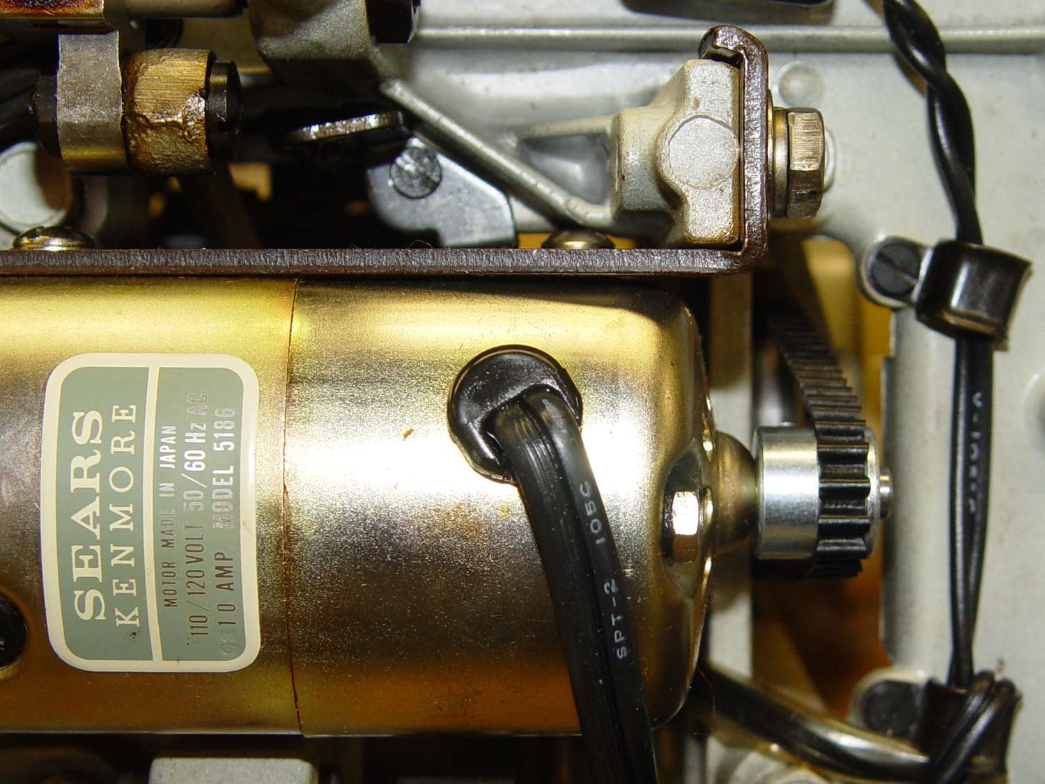
The Kenmore Model 158 sewing machine contains a 120 VAC / 1 A motor that powers all the moving parts through a V belt:
Kenmore 158 – AC drive motor – overview
Looking up through the body:
Kenmore 158 – AC motor and belt – bottom
A double pulley on a jackshaft reduces the motor speed on the way to the handwheel:
Kenmore 158 – handwheel – jackshaft pulley
The motor and handwheel turn counterclockwise in normal operation, but can be turned clockwise by hand as needed. The belt tension isn’t very high and the jackshaft pulleys can slip, but I’m not sure if that’s intentional or the result of several decades of runtime.
Despite the cogged belt, the pulleys are smooth; it’s not a positive-drive transmission with timing-belt pulleys.
You could, if you had to, run a belt from the handwheel directly to the motor, although the pulley would ride about 7 mm further out on the shaft. I have no way to measure the lengths with any confidence in the results; one could calculate the lengths based on pulley diameters and center spacing.
Sticking retroreflective tape on the pulleys and handwheel, then deploying the laser tachometer, provides some minimum and maximum speeds:
Motor: 2100 – 8500 rpm
Jackshaft: 800 – 3200 rpm
Handwheel: 200 – 930 rpm
Those aren’t entirely consistent, because I’m using the old foot pedal speed control with its defunct carbon disks; the low end, in particular, isn’t as slow as it can go.
In any event, there’s about a 10:1 speed reduction from motor to handwheel.
The motor label clearly states that it’s 100-120 V AC, but it has brushes, so it’s actually a universal-wound motor that should run happily on DC.
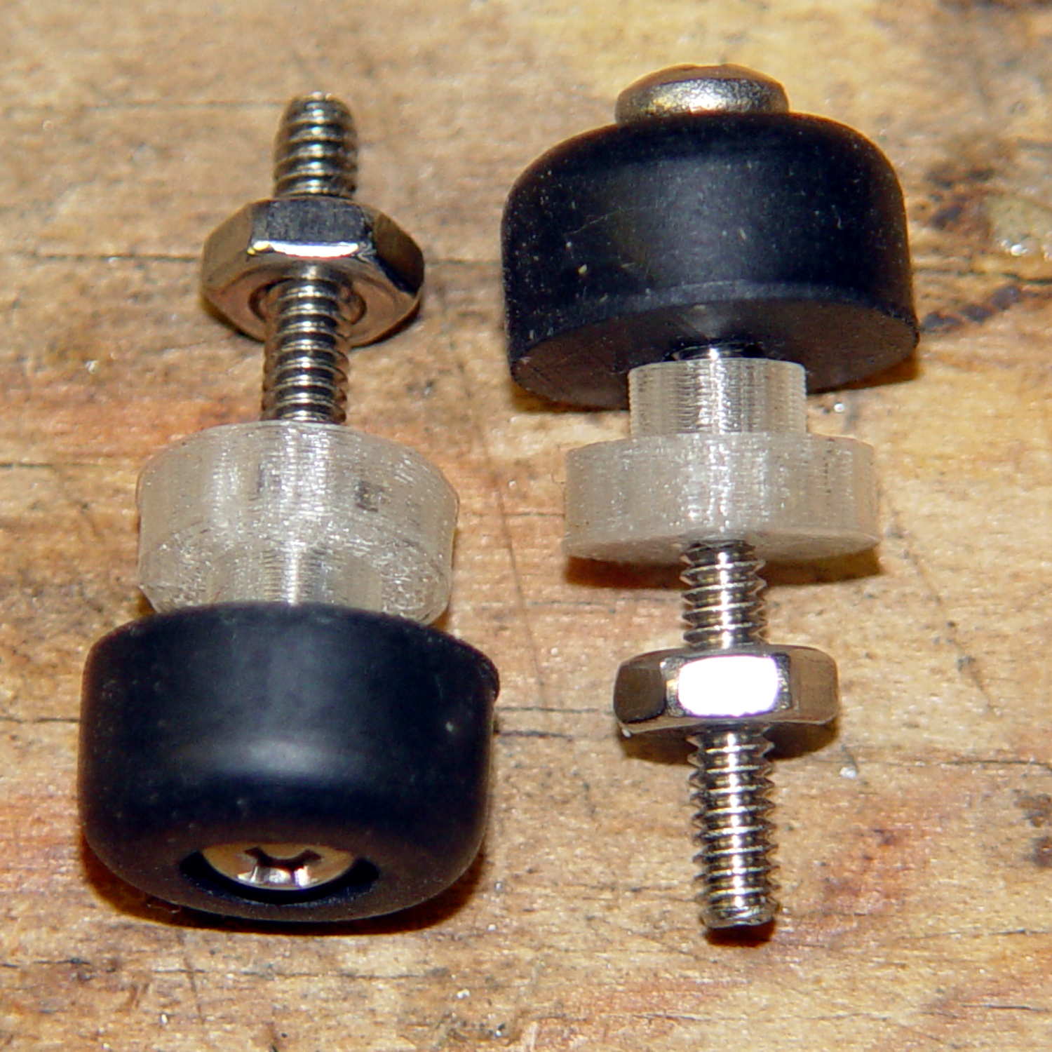
As you’d expect, the soft feet on the bottom of the Kenmore Model 158 sewing machine’s foot pedal control turn into hard buttons after a few decades. The OEM feet have mushroom tops that push through holes in the case and latch in place; of course, none of the rubber feet in my collection match the hole diameter or case thickness.
No problem! Design a bushing that fits the case hole and passes a 4-40 screw:
Speed Control Foot Bushing
Then print up a handful, add screws to fit the rubber feet, and top off with nuts:
Kenmore 158 – pedal foot bushing – detail
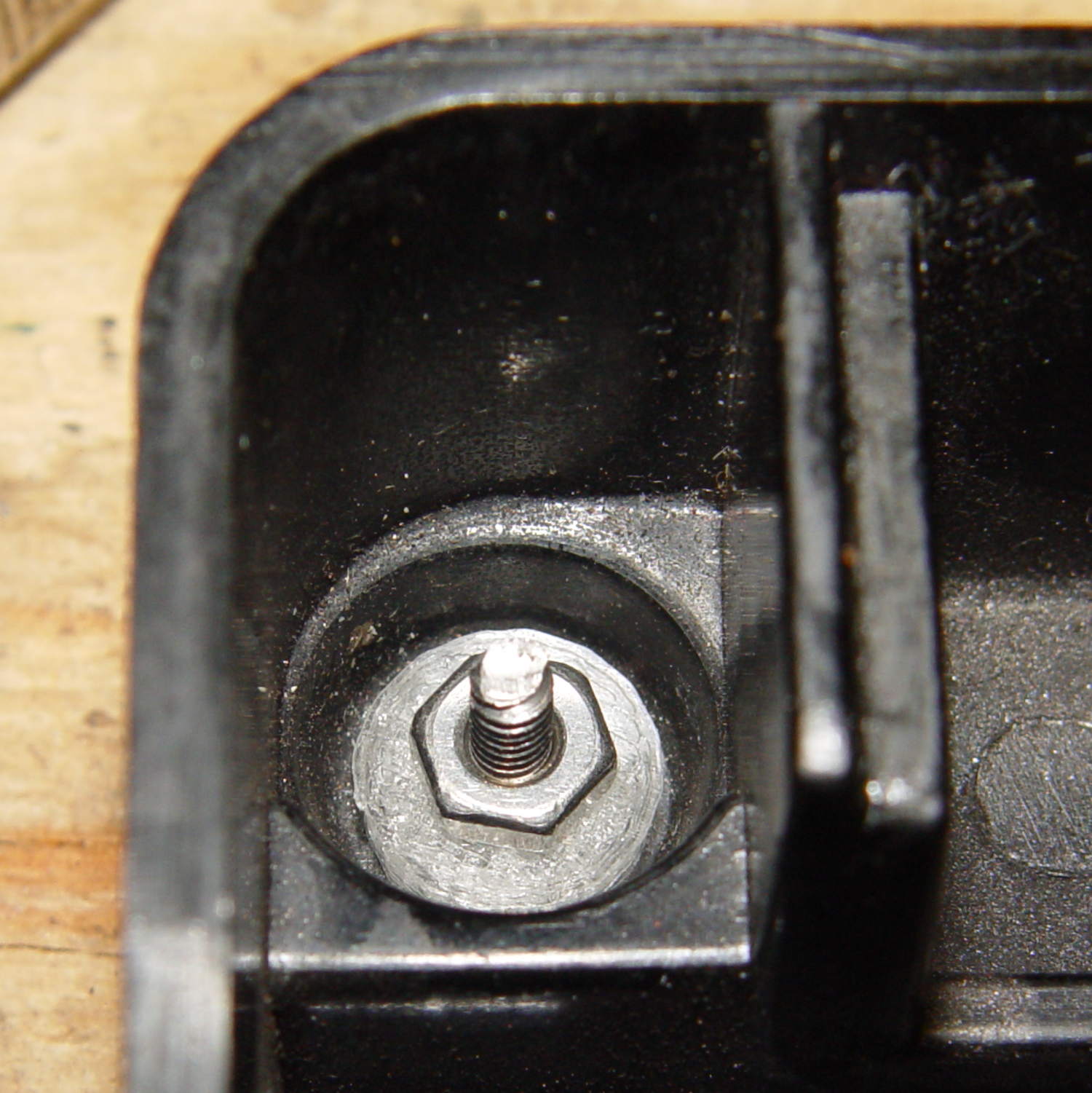
Installed, with the screws cropped to a suitable length, they look about like you’d expect:
Kenmore 158 – pedal foot bushing – interior
Turns out that the springs supporting the foot pedal rest in those pockets, so the bushing reduces the spring travel by a few millimeters. The springs aren’t completely compressed with the pedal fully depressed, so it’s all good.
The OpenSCAD source code:
// Kenmore Model 158 Sewing Machine Foot Control Bushings
// Ed Nisley - KE4ZNU - June 2014

//- Extrusion parameters must match reality!
//  Print with 2 shells and 3 solid layers

ThreadThick = 0.20;
ThreadWidth = 0.40;

HoleWindage = 0.2;			// extra clearance

Protrusion = 0.1;			// make holes end cleanly

function IntegerMultiple(Size,Unit) = Unit * ceil(Size / Unit);

//----------------------
// Dimensions

Stem = [2.5,5.7];			// through the case hole
Cap = [3.0,10.0];			// inside the case

LEN = 0;
DIA = 1;

OAL = Stem[LEN] + Cap[LEN];

ScrewDia = 2.8;				// 4-40 generous clearance

//----------------------
// Useful routines

module PolyCyl(Dia,Height,ForceSides=0) {			// based on nophead's polyholes

  Sides = (ForceSides != 0) ? ForceSides : (ceil(Dia) + 2);

  FixDia = Dia / cos(180/Sides);

  cylinder(r=(FixDia + HoleWindage)/2,
           h=Height,
           $fn=Sides);
}

module ShowPegGrid(Space = 10.0,Size = 1.0) {

  RangeX = floor(100 / Space);
  RangeY = floor(125 / Space);

	for (x=[-RangeX:RangeX])
	  for (y=[-RangeY:RangeY])
		translate([x*Space,y*Space,Size/2])
		  %cube(Size,center=true);

}

//----------------------
// Build it!

ShowPegGrid();

difference() {
	union() {
		cylinder(d=Stem[DIA],h=OAL,$fn=16);
		cylinder(d=Cap[DIA],h=Cap[LEN],$fm=16);
	}
	translate([0,0,-Protrusion])
		PolyCyl(ScrewDia,OAL + 2*Protrusion,6);
}