Ed Nisley's Blog: Shop notes, electronics, firmware, machinery, 3D printing, laser cuttery, and curiosities. Contents: 100% human thinking, 0% AI slop.
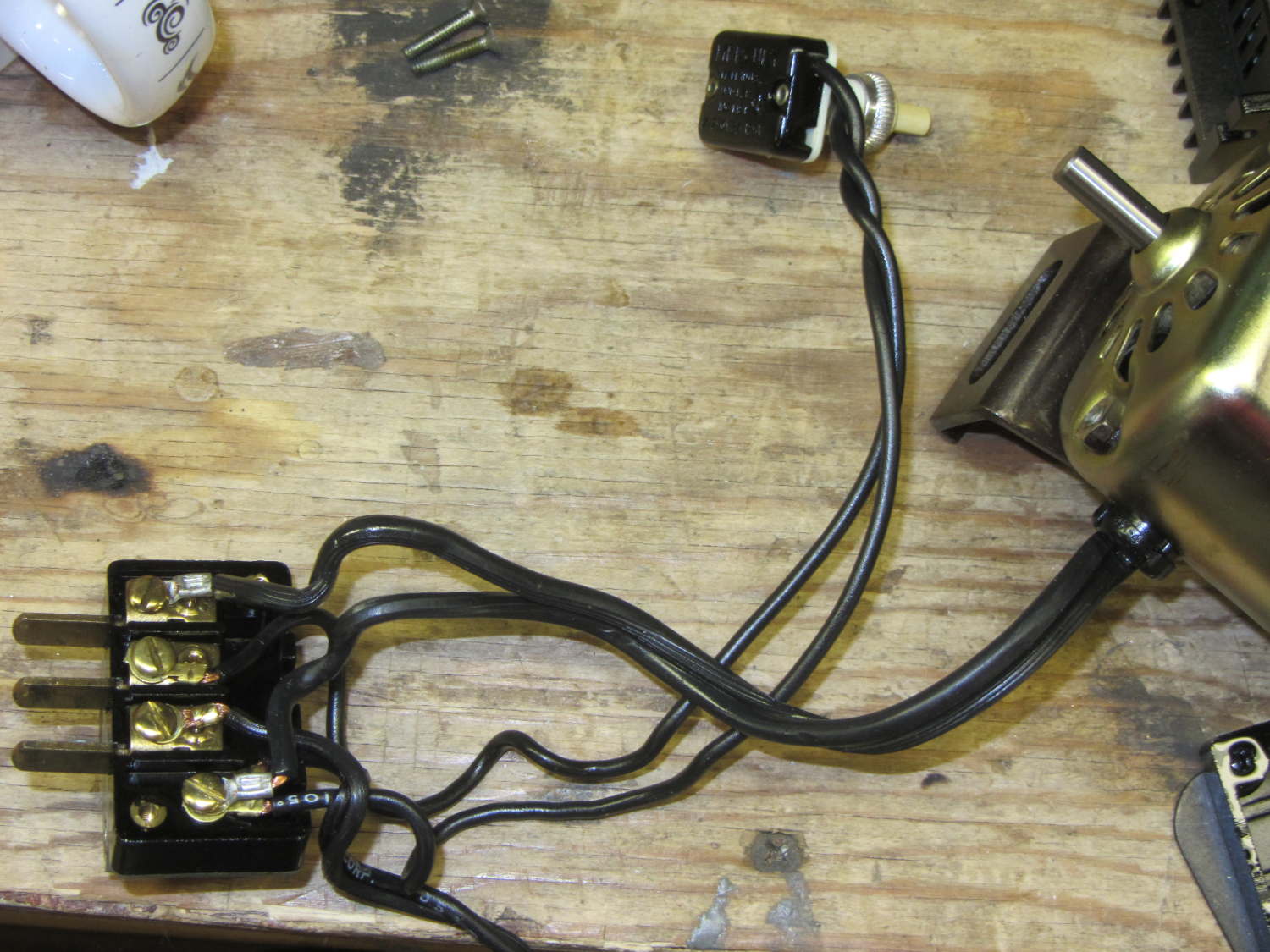
The original Kenmore Model 158 sewing machine used a two-wire line cord:
Kenmore 158 – terminal block
In light of my modifications, grounding the frame seems prudent. The heap produced a long IEC extension cord with screw-mounting ears on the socket end that fit neatly into the GX270’s rear panel area occupied by two PCI cover plates, so a bit of Quality Shop Time seemed in order.
The GX270’s carcass yielded a complex bit of sheet metal that held the hard drive and a few other odds & ends, with some clean right-angle bends in exactly the right places:
Dell drive bracket – intact
Some bandsaw work removed the gimcrackery:
Dell drive bracket – first bandsaw pass
More bandsawing produced a rough outline:
Dell drive bracket – second bandsaw pass
Sawing to length, removing the small flanges, and squaring the sides:
Dell drive bracket – squaring edges
I traced the existing PCI cover tabs, bandsawed the outlines, and filed to suit:
Dell drive bracket – basic outline
They look a bit ragged, but fit well enough:
Dell drive bracket – trial fit – interior
From the outside, it looks like it grew there:
Dell drive bracket – trial fit – exterior
The divider between the PCI slots succumbed to tin snips and a bit of filing. The tabs climbing over the bottom edge come from the internal EMI shield covering the entire back surface.
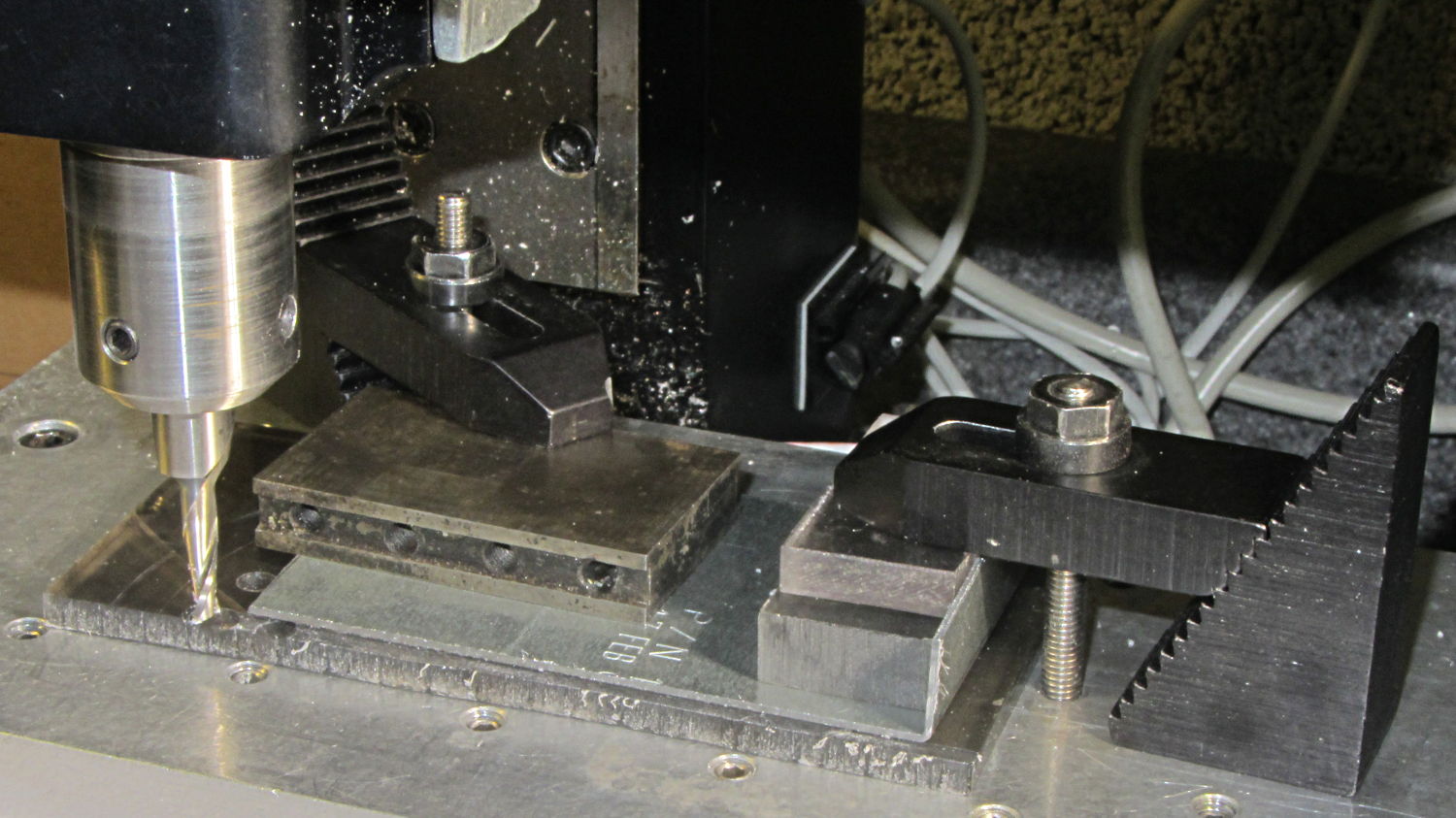
A bit of coordinate drilling and manual milling produced the IEC socket outline
Dell drive bracket – drilling and milling
Which looks pretty good from the inside:
Dell drive bracket – IEC socket – interior
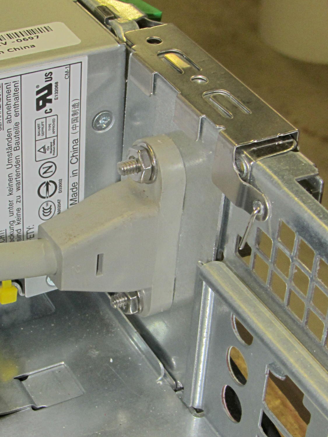
And great from the outside, if I do say so myself:
Dell drive bracket – IEC socket – exterior
Match-drilling a #6 clearance hole below the hole in the clamp arm, then ramming a self-tapping case screw into it, provides a convenient grounding point for the sewing machine cord:
IEC Socket Mount – ground screw
The chassis lid has two matching holes for those screw heads, which would ordinarily hold the two PCI cards in place. I could remove the clamp arm, but it doesn’t get in the way of anything.
Under ordinary circumstances, a fuseholder mounts in a square-ish panel cutout, but there’s no convenient panel to be found in the repurposed GX270 case. So now there’s a holder for the fuseholder stuck to the side of the power supply inside the case:
Fuseholder – installed
The square tube covers the entire fuseholder, with the quick-connect tabs protruding from the back, to provide enough surface area for the double-stick foam tape.
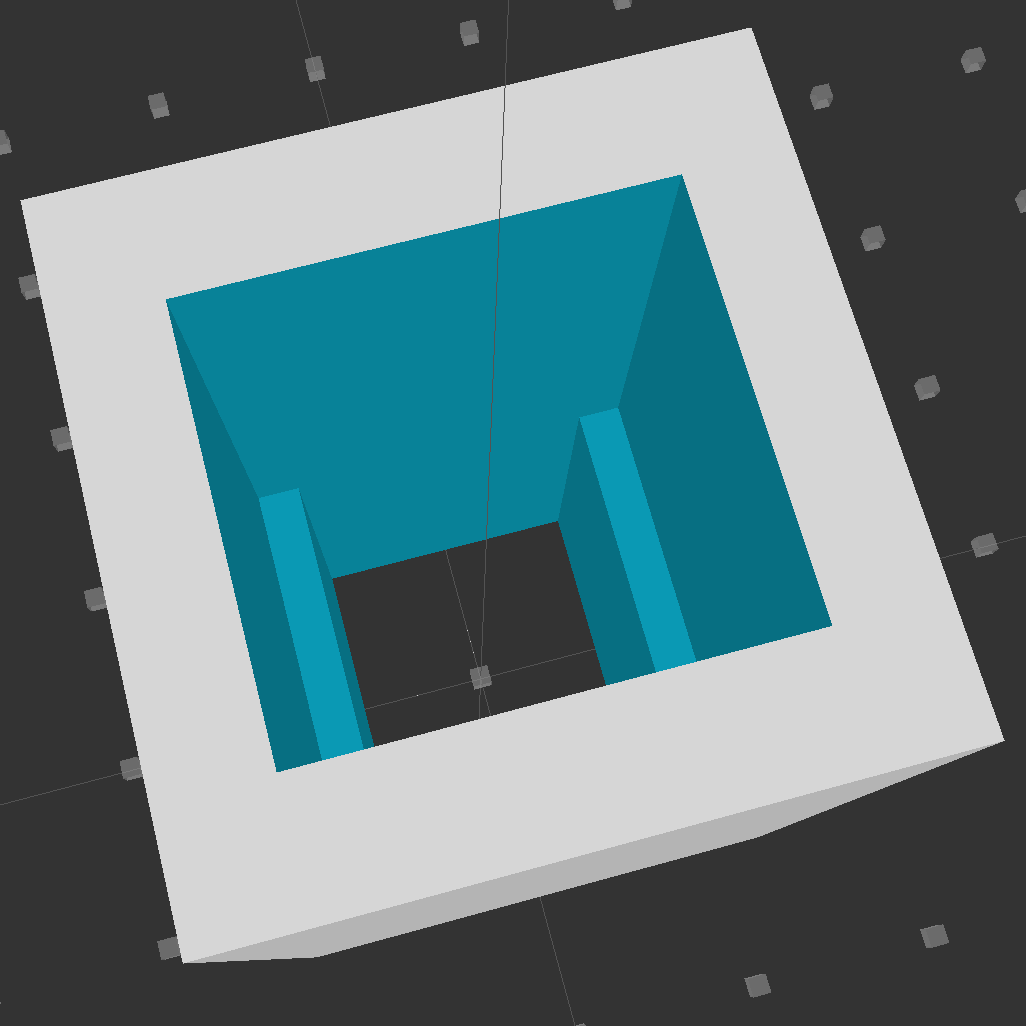
Looking down into the solid model, you can see the reduced width near the back end:
Fuseholder Holder
The black fuseholder contains a 5 A fast blow fuse, which should be entirely adequate for normal operation. In the event that a wire breaks loose and contacts the metal shell surrounding the whole chassis, it will pop instantly. That won’t disable the power supply, but it will remove line voltage from the entire motor controller chassis.
Remember that the source power line goes to the center QC tab, thus burying the always-hot contact deep in the fuseholder.
The OpenSCAD source code:
// Fuseholder mount
// Ed Nisley - KE4ZNU - August 2014

//- Extrusion parameters must match reality!

ThreadThick = 0.20;
ThreadWidth = 0.40;

HoleWindage = 0.2;			// extra clearance

Protrusion = 0.1;			// make holes end cleanly

AlignPinOD = 1.70;			// assembly alignment pins: filament dia

function IntegerMultiple(Size,Unit) = Unit * ceil(Size / Unit);

//----------------------
// Dimensions

Shell = [25.0,25];						// outside = bezel size + some stiffening

Mount = [17.3,15.7,21.0];					// mount section = slight compression in X
Base = [13.5,15.7,17.0];					// clearance over crimped contact

OAL = Mount[2] + Base[2];

//----------------------
// Useful routines

module PolyCyl(Dia,Height,ForceSides=0) {			// based on nophead's polyholes

  Sides = (ForceSides != 0) ? ForceSides : (ceil(Dia) + 2);

  FixDia = Dia / cos(180/Sides);

  cylinder(r=(FixDia + HoleWindage)/2,
           h=Height,
           $fn=Sides);
}

module ShowPegGrid(Space = 10.0,Size = 1.0) {

  RangeX = floor(100 / Space);
  RangeY = floor(125 / Space);

	for (x=[-RangeX:RangeX])
	  for (y=[-RangeY:RangeY])
		translate([x*Space,y*Space,Size/2])
		  %cube(Size,center=true);

}

//----------------------
// Build it

ShowPegGrid();

difference() {
	translate([0,0,OAL/2])
		cube([Shell[0],Shell[1],OAL],center=true);
	translate([0,0,Base[2] + Mount[2]/2])
		cube(Mount + [0,0,2*Protrusion],center=true);
	translate([0,0,Base[2]/2])
		cube(Base + [0,0,2*Protrusion],center=true);
}
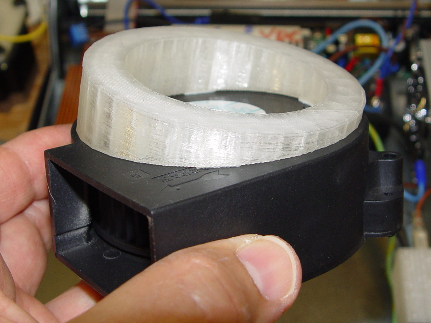
This angled ring fits under a repurposed CPU cooler:
Blower Mount – solid model
Viewed perpendicular to the angled surface, it’s a circle, so what looks like a vertical cylinder is actually slightly oval to make the top come out right. That way, the walls are vertical, not angled, and it doesn’t stand crooked on the base plate.
Such a shape is trivially easy for a 3D printer:
Blower mount – on build platform
And looks about like you’d expect on the blower, which is why that surface must be a circle:
Blower Mount – bottom view
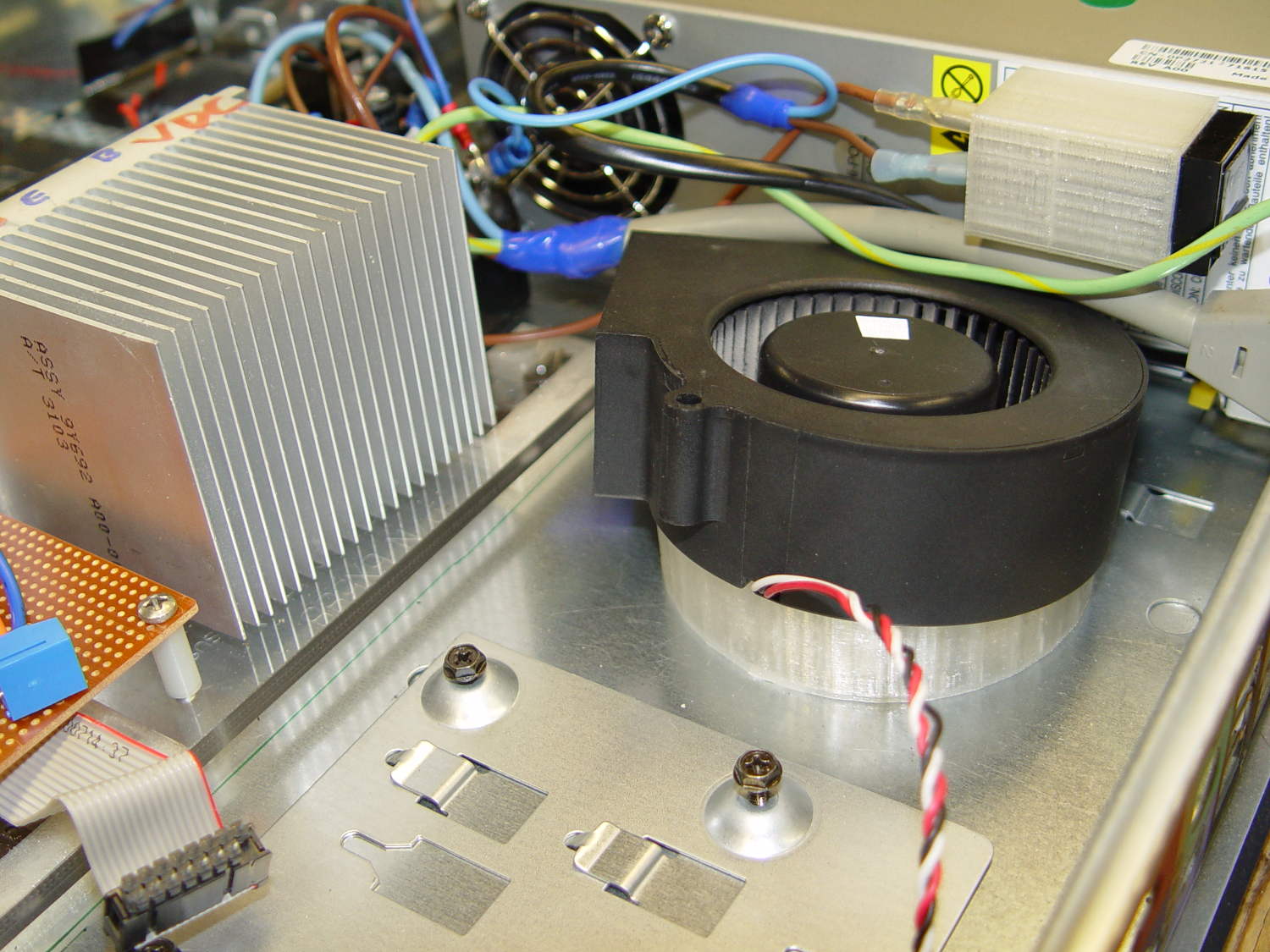
A trial fit in the case, along with a bunch of parts I haven’t written up yet:
Blower Mount – installed
Under normal circumstances, you’d want the blower a bit higher and level, but there just wasn’t anywhere else to fit the fuseholder. Besides, this way the airflow goes slightly upward toward the clearance over the top of that monster heatsink. Some air flows along the side of the heatsink to cool the isolated power supply you can’t quite see in the far corner of the chassis beyond that tangle of wires.
The angle seems pretty close to right, although I must get the rest of the circuitry running to know if the airflow can actually transfer the heat from the heatsink out of the case.
It doesn’t take much OpenSCAD source code to define the shape:
// Blower mount
// Ed Nisley - KE4ZNU - August 2014

//- Extrusion parameters must match reality!

ThreadThick = 0.20;
ThreadWidth = 0.40;

HoleWindage = 0.2;			// extra clearance

Protrusion = 0.1;			// make holes end cleanly

AlignPinOD = 1.70;			// assembly alignment pins: filament dia

function IntegerMultiple(Size,Unit) = Unit * ceil(Size / Unit);

//----------------------
// Dimensions

MountOD = 85.0;						// a bit smaller than the housing OD

MountID = 60.0;						// carve out to reduce printing time

Base = 5.0;							// minimum thickness (allowing for some overhang)

ElevationAngle = atan(20/90);		// net tilt across fan base

ElevationDelta = MountOD * tan(ElevationAngle);

echo(str("Elevation angle: ",ElevationAngle," delta: ",ElevationDelta));

//----------------------
// Useful routines

module PolyCyl(Dia,Height,ForceSides=0) {			// based on nophead's polyholes

  Sides = (ForceSides != 0) ? ForceSides : (ceil(Dia) + 2);

  FixDia = Dia / cos(180/Sides);

  cylinder(r=(FixDia + HoleWindage)/2,
           h=Height,
           $fn=Sides);
}

module ShowPegGrid(Space = 10.0,Size = 1.0) {

  RangeX = floor(100 / Space);
  RangeY = floor(125 / Space);

	for (x=[-RangeX:RangeX])
	  for (y=[-RangeY:RangeY])
		translate([x*Space,y*Space,Size/2])
		  %cube(Size,center=true);

}

//----------------------
// Build it

ShowPegGrid();

difference() {
	scale([1,cos(ElevationAngle),1])
		cylinder(d=MountOD,h=Base + ElevationDelta);
	translate([-MountOD,-MountOD/2,Base])
		rotate([ElevationAngle,0,0])
			cube([2*MountOD,2*MountOD,ElevationDelta],center=false);
	translate([0,0,-Protrusion])
		cylinder(d=MountID,h=Base + 3*ElevationDelta);
}
Dell built the GX270 I’m repurposing back in 2004, early on in the capacitor plague years, but only one of the system board caps showed signs of leakage:
Capacitor plague – 2004 Dell Edition
While I was harvesting some of the connectors, it occurred to me that those powdered iron inductors might make good current sensors, as they’re already wound with heavy gauge copper wires.
I picked an inductor with enough turns and, although slitting didn’t pose much of a problem, the saw did make a mess of the turns adjacent to the cut:
Powdered iron toroid – slitting
Iron powder has more magnetic remnance than ferrite, to the extent that iron swarf clogged the gap. After the first pass, I ran the slit toroid through the degausser to shake it clean and see what damage had been done. It looked OK, so I realigned it on the saw blade and continued the mission, with all the dust vanishing into the vacuum cleaner’s snout.
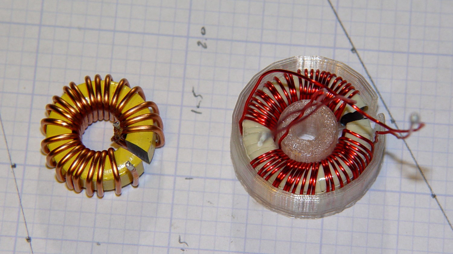
Removing the damaged sections left 22 turns. For comparison, I converted the 56 turn ferrite toroid into a 25 turn model by paralleling two 25 turn sections:
Slit toroids – iron – ferrite
The enamel wire on the iron toroid measures 40 mil diameter, close enough to 18 AWG.
Paralleling two 24 AWG windings on the ferrite toroid produces twice the copper area of a single winding, so the resistance is the same as a single 21 AWG winding (3 AWG steps = factor of two area change). That’s three steps smaller than the 18 AWG on the iron toroid, so the resistance is a factor of two larger than the heavier wire.
The paralleled winding has the advantage of reducing the power dissipation required to produce the same magnetic flux density, without the difficulty of winding heavier wire. That may not actually matter, given the relatively low currents required by the motor in normal operation.
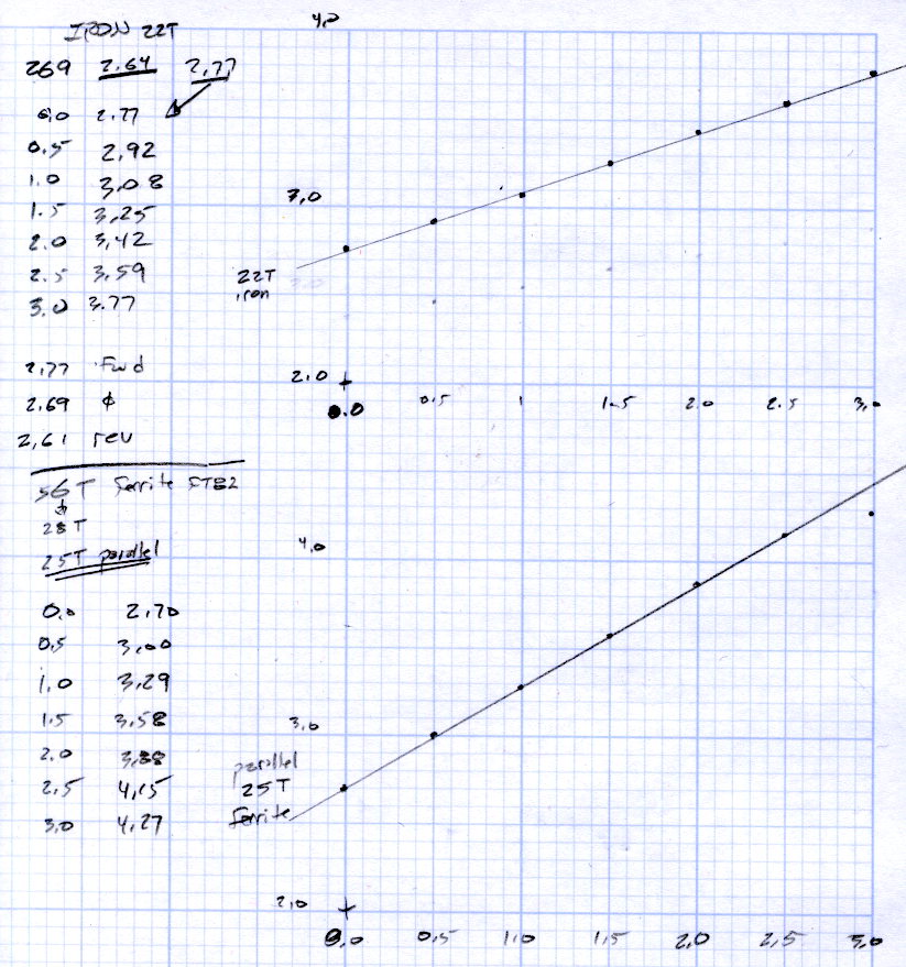
Wedging a Hall sensor into the gaps and stepping the current produced two useful graphs:
Iron and ferrite toroids – Hall sensor output
The iron toroid has lower permittivity (less flux density for a given magnetizing force), which means the full-scale range exceeds 3 A and the useful range up to 1 A covers only 300 mV.
The last point on the ferrite curve shows the Hall sensor output saturating just over 4 V, with 1.5 V of range.
The slope, in mV/A
Powdered iron: 340
Ferrite: 540
Boosting the slope of the powdered iron by 25/22 gives 386 mV/A, so the iron permeability really is 70% of the ferrite. That’s modulo the gap size, of course, which surely differs by enough to throw out all the significant digits.
Obviously, an op amp circuit to remove the offset and rescale the output to 0-5 V will be in order.
The previous graph for the ferrite toroid with the complete 56 turn winding shows, as expected, about twice the output of this 25 turn version:
FT82-43 – 56 turns – 24 AWG
The linear part of that line is 1375 mV/A, although I can’t vouch that the data came from the same Hall effect sensor. Scaling it by 25/56 gives 613 mV/A, suggesting it’s not the same sensor.
Having developed an emotional attachment to the ferrite toroid, I’ll use it in the first pass of the current feedback circuit. If the motor need a bit less sensitivity or lower resistance, the powdered iron toroid looks like a winner.
Memo to self: Always degauss iron toroids before slitting!
The general idea is to gut an old Dell Optiplex GX270 and stuff the high-voltage parts of the sewing machine controller inside a well constructed and solidly grounded metal shield inside a not-too-ugly plastic box. It’d be nice to reuse the power control button and status LEDs on the front panel…
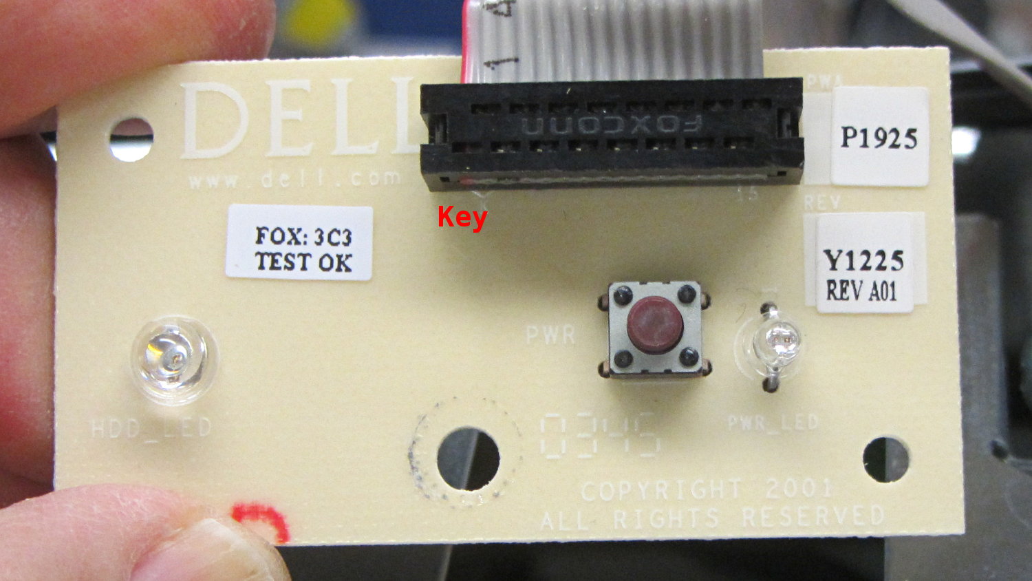
The few parts on the front of the through-hole board:
Dell Power Button PCB – component
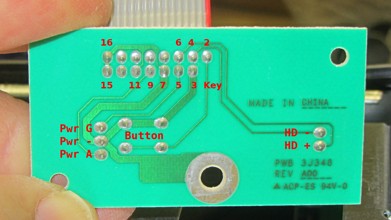
The copper side, with annotations:
Dell Power Button PCB – copper
The red tracer on the ribbon cable goes to Pin 1, which is a blind key on the PCB.
The LEDs do not have ballast resistors, so those must go on a circuit board somewhere else.
The case from a Dell Optiplex GX270 will hold the Kenmore 158 sewing machine’s motor control electronics, because it has a well-grounded metal box inside the plastic shell that will protect fragile humans from line voltages. The GX270 power supply will suffice for the usual stuff, but the bridge rectifier, power transistor, and suchlike require a direct connection to the AC line.
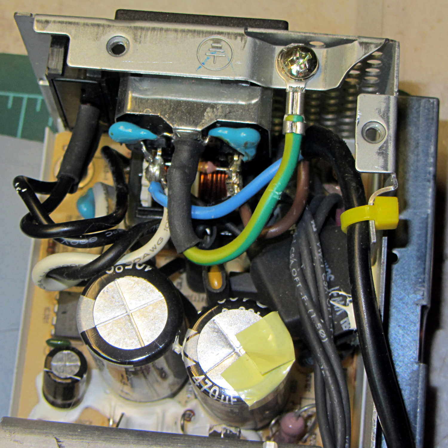
Rather than add another plug, I soldered a nice two-wire line cord to the IEC socket terminals inside the GX270’s power supply:
Modified Dell power supply – interior
The cord follows the IEC/EU standard color code:
Blue – neutral
Brown – hot
The power supply follows the US standard color code:
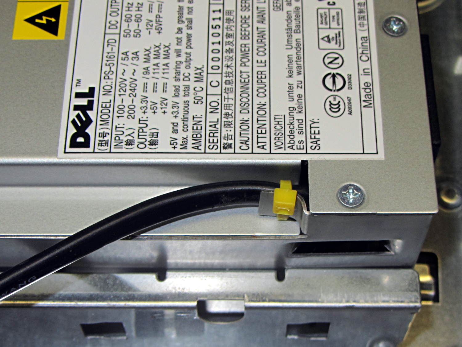
The yellow cable tie anchors the cord to a metal tab that, when bent at right angles, provides a convenient exit from the power supply at exactly the right location:
Modified Dell power supply – AC cord exit
The power supply mounts with the label facing inward, directly adjacent to the PCI slot covers. The new cord emerges near the bottom, inside the recess that formerly accommodated the board.
Definitely not UL approved, but we’re well beyond that stage anyway…
A Squidwrench Weekly Doings being useful for short-attention-span projects, I measured the DC current gain for all five ET227 transistors. The test conditions fall far below the ET227’s 1 kV / 100 A ratings, but they’re roughly what the sewing machine motor controller calls for.
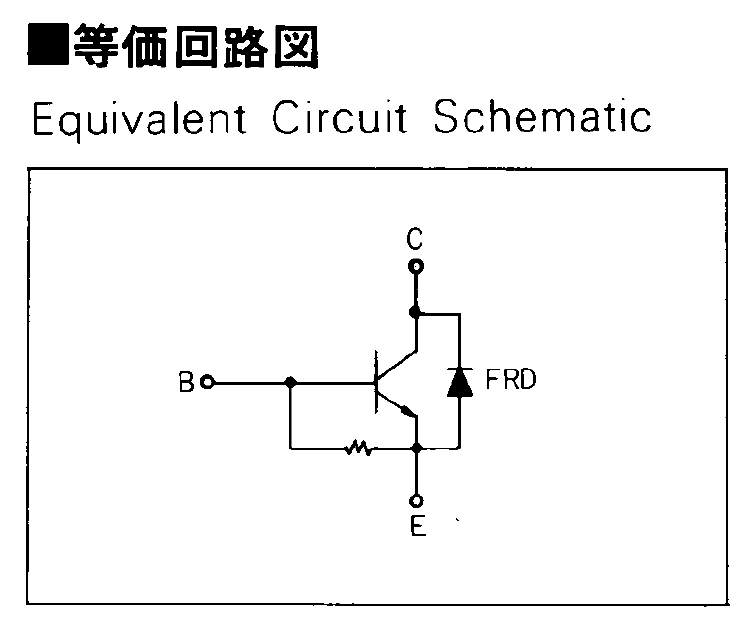
The transistors don’t even begin to turn on until IB gets over about 50 mA, because there’s a 13 Ω shunt resistor (as measured, for either polarity) between the base and emitter terminal:
Fuji ET227 – equivalent circuit
In the ET227’s normal use, that resistor dumps the Miller effect charge injected from the collector (with the intent of improving the switching time), but you must ram nearly 70 mA into the resistor to get 900 mV at the base, so the actual transistor base current isn’t all that high for low collector currents. But you measure gain by dividing goes-outa by goes-inta, so that’s what I’ll do.
The ET227 needs something like IB = 30 A to switch 100 A at the collector, so a few dozen mA into that resistor rounds off to zilch for its usual driver circuit. FWIW, with IB = 30 A, VBE tops out at 2 V: the resistor carries 150 mA and dissipates 300 mW.
Anyhow, randomly labeling the transistors from A (on the heatsink) through E, then hitching them up to a 1.8 A bench supply with a 33 Ω resistor to the base terminal provided some readings at single-digit collector voltages.
For IB = 72 mA:
IB
IC
hFE
A
72
490
6.8
B
73
540
7.4
C
74
480
6.5
D
75
440
5.9
E
76
520
6.8
For IB = 108 mA, with one bumped-knob outlier:
IB
IC
hFE
A
108
1220
11.3
B
101
1190
11.8
C
108
1280
11.9
D
108
1170
10.8
E
108
1320
12.2
Although the gain around 1 A comes out slightly higher than while running the motor, it’s in the same ballpark. This is not a high-gain device: it’ll need a driver after the optoisolator to squeeze enough current through the collector.
Eks tried to unload a huge old Tek transistor curve tracer on me that would be ideal for this sort of thing. I’m still not tempted…